Table of Contents
Advertisement
Quick Links
P5-20...L120-11
Model: E16
Assembly and Operating Instructions
en
Sun protection drives for locking systems
Important information for:
• Fitters / • Electricians / • Users
Please forward accordingly!
These instructions must be kept safe for future reference.
2010 300 953 0b 13/09/2022
Becker-Antriebe GmbH
Friedrich-Ebert-Straße 2-4
35764 Sinn/Germany
www.becker-antriebe.com
Advertisement
Table of Contents

Related Manuals for Becker R12-17-E16


Summary of Contents for Becker R12-17-E16
- Page 1 Sun protection drives for locking systems Important information for: • Fitters / • Electricians / • Users Please forward accordingly! These instructions must be kept safe for future reference. 2010 300 953 0b 13/09/2022 Becker-Antriebe GmbH Friedrich-Ebert-Straße 2-4 35764 Sinn/Germany www.becker-antriebe.com...
-
Page 2: Table Of Contents
Table of contents General .................................... 3 Warranty ..................................... 3 Safety instructions ................................ 4 Instructions for the user.............................. 4 Instructions for installation and commissioning........................ 4 Intended use .................................. 6 Assembling and disassembling the plug-in connecting cable.................... 6 Assembly .................................... 7 Setting the limit positions using the programming unit...................... 9 Deleting the limit positions using the programming unit ...................... -
Page 3: General
General These tubular drives are high-quality products with the following features: • Optimised for sun protection applications with locking system • freely programmable locking and unlocking limit position • Automatic detection of upper limit position • Automatic detection of lower limit position when the locking system is activated •... -
Page 4: Safety Instructions
Safety instructions The following safety instructions and warnings are intended to avert hazards and to prevent property damage and personal injury. Instructions for the user General information • The drive must be disconnected from its power source during cleaning and maintenance and when re- placing parts. - Page 5 • If the drive is used for shading solutions in a specially marked area (e.g., escape routes, hazard zones, safety areas), compliance with all applicable regulations and standards must be ensured. • Once the drive has been installed, the fitter must mark the used tubular drive in the “Technical data” chapter and make a note of the installation position.
-
Page 6: Intended Use
Intended use The type of tubular drive described in these instructions is intended solely for the operation of sun protection systems with locking system. To function properly, these tubular drives need a fixed stop in the upper limit position (retracted sun protection). It may only be used in networked systems if all the individual drives are exactly synchronised and reach the limit positions at the same time. -
Page 7: Assembly
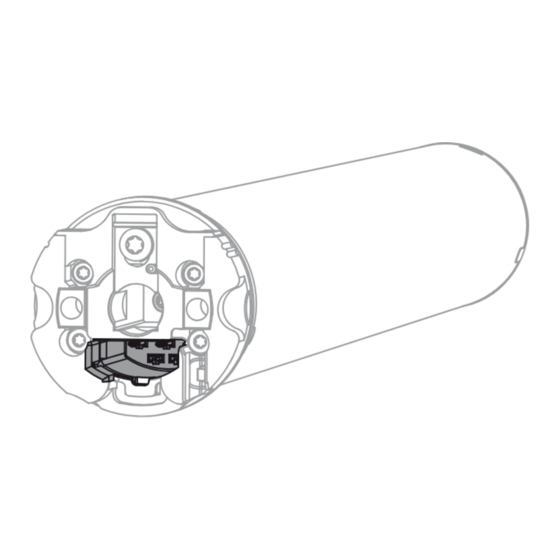
Ø45/Ø58 Insert a suitable flathead screwdriver right into the recess of the locating latch, so that the latch releases the locating lug from the plug. Now you can pull out the connecting cable along with the flat- head screwdriver. A = locating latch Assembly Assembling the drive Attention... - Page 8 Assembling and disassembling the drive adapter with drive adapter safety catch or screw connection Assembling and disassembling the drive Assembling and disassembling the drive adapter with separate drive adapter adapter with screw connection safety catch Mounting the drive in the tube For profile shafts: In the case of some drive adapters, tolerances of the groove widths in different barrels can be offset by rotating the drive adapter into a different groove recess.
-
Page 9: Setting The Limit Positions Using The Programming Unit
Setting the limit positions using the programming unit Programming button Travel button black black brown brown blue blue green-yellow green-yellow Unlocked Locked Locking bolt Moving part of the locking system on the front section of the sun protection system Bolt mechanism Fixed part of the locking system in the guide track of the sun protection system Connect the wires of the tubular drive to those of the same colour in the programming unit (Item No. -
Page 10: Deleting The Limit Positions Using The Programming Unit
Use the travel button to run the bolt in the open direction until it is engaged by the bolt mechanism. ▻ The tubular drive switches off automatically. Use the travel button to run the bolt in the down direction and disengage it from the bolt mechanism, then stop the tubular drive. -
Page 11: Adjusting The Limit Positions With A Rotary Switch Or A Locking Button
Adjusting the limit positions with a rotary switch or a locking button black black brown brown blue blue green-yellow green-yellow Unlocked Locked Locking bolt Moving part of the locking system on the front section of the sun protection system Bolt mechanism Fixed part of the locking system in the guide track of the sun protection system Connect the wires of the tubular drive to those of the same colour in the rotary switch or a locking button and switch on the power supply. -
Page 12: Deleting The Limit Positions With A Rotary Switch Or A Locking Button
Use the travel button to run the bolt in the open direction until it is engaged by the bolt mechanism. ▻ The tubular drive switches off automatically. Run the bolt in the down direction and disengage it from the bolt mechanism, then stop the tubular drive. -
Page 13: Information For The Electrician
Information for the electrician Tubular drives with electronic limit switching can be connected in parallel. The maximum switching contact load of the switching equipment (timer, relay control, switch, etc.) must be observed. To operate drives with electronic limit switching, only use switch- ing elements (timers) that are not earthed via the drive. -
Page 14: Technical Data Dia. 45
Technical data dia. 45 Tubular drive R8-17 R12-17 R20-17 R30-17 R40-17 Model Type C SE I2 Rated torque [Nm] Output speed [rpm] Limit switch range 64 revolutions Supply voltage 230 V AC / 50 Hz Connected load [W] Rated current consumption [A] 0.45 0.50 0.75 0.90 1.15... -
Page 15: What To Do If
Tubular drive L100-11 L120-11 Model Type C SE I2 Rated torque [Nm] Output speed [rpm] Limit switch range 64 revolutions Supply voltage 230 V AC / 50 Hz Connected load [W] Rated current consumption [A] 1.56 1.90 Operating mode S2 4 min Degree of protection IP 44 Min. -
Page 16: Sample Wiring Diagram
Sample wiring diagram The assignment of the black and brown wires according to the direction of travel is de- pendant on how the drive is installed (mounted to the right or to the left). Controlling one/several drive(s) via a single switch/button 16 - en... -
Page 17: Declaration Of Conformity
Declaration of conformity For UK-Markets: The Declaration of Conformity can be provided upon request from Becker Motors Ltd., or can be downloaded on www.beckermo- tors.co.uk. 17 - en...
Need help?
Do you have a question about the R12-17-E16 and is the answer not in the manual?
Questions and answers