Sungrow IDC30E User Manual
Dc charger
Hide thumbs
Also See for IDC30E:
- Quick installation manual (10 pages) ,
- Quick installation manual (41 pages)

Related Manuals for Sungrow IDC30E


Summary of Contents for Sungrow IDC30E
- Page 1 User Manual DC Charger IDC30E IDC30EDC ChargerUser ManualIDC30E-UEN- Ver13-202307 IDC30E-UEN-Ver13-202307...
-
Page 3: All Rights Reserved
Software Licenses • It is prohibited to use data contained in firmware or software developed by SUNGROW, in part or in full, for commercial purposes by any means. • It is prohibited to perform reverse engineering, cracking, or any other operations that compromise the original program design of the software developed by SUNGROW. -
Page 4: About This Manual
Please read this manual carefully before using the product and keep it properly at a place for easy access. All contents, pictures, marks, and symbols in this manual are owned by SUNGROW. No part of this document may be reprinted by the non-internal staff of SUNGROW without written authorization. -
Page 5: Table Of Contents
Contents All Rights Reserved .....................I About This Manual......................II 1 Safe Instructions ....................1 1.1 Symbols ......................1 1.2 Packaging, Shipping and Storage ..............2 1.3 Operations .....................3 1.4 Maintenance and Replacement ...............4 2 Product Introduction ..................5 2.1 Introduction ....................5 2.2 Production Introduction ...................6 2.2.1 Appearance and Dimensions ..............6 2.2.2 Internal Structure ..................6 2.2.3 External Port..................7... - Page 6 2.4.5.3 Install the Handles ..............16 2.4.5.4 Charger Installation..............17 2.4.5.5 Remove the Handles ..............17 2.4.5.6 Secure the Charger ..............18 2.4.5.7 Install the Charging Connector Socket.........18 2.4.5.8 Connect the Cable Connection Terminal........19 2.4.5.9 Ethernet Cable Connection............22 2.4.5.10 SIM Card Installation..............23 2.4.6 Pole-mounted Installation (Optional).............23 2.4.6.1 Pole Components ..............24 2.4.6.2 Recommended Construction Scheme for Charger Foundation ................25...
- Page 7 3.2.2.2 Plug&Play .................48 4 Operation and Maintenance Mode ..............50 4.1 Login and Logout..................51 4.1.1 Login....................51 4.1.2 Logout....................52 4.2 Function Description ..................52 4.2.1 CCU Info ....................52 4.2.2 Version....................56 4.2.3 Config_1 ....................57 5 Faults and Troubleshooting ................61 5.1 TCU ......................61 5.2 CCU ......................65 5.3 LLC ......................67 5.4 PFC......................71 5.5 Charging Stop Code ..................75...
-
Page 9: Safe Instructions
Safe Instructions Symbols This manual contains important safety instructions, which are highlighted with the following symbols, to ensure personal and property safety during usage, or to help optimize the prod- uct performance efficiently. Indicates high-risk potential hazards that, if not avoided, may lead to death or seri- ous injury. -
Page 10: Packaging, Shipping And Storage
After arrival of goods, check for transport damage and, if any, contact the shipping company or SUNGROW. Check if the content inside the package matches the delivery list. Non-professional personnel shall not disassemble the components. -
Page 11: Operations
It is strictly prohibited to use the charger when the charging connector or the charging cable is defective, appears cracked, frayed, broken, or otherwise dam- aged. If any anomaly is found, please, refer to the seller or SUNGROW If there is any abnormality during use, please press the emergency stop button im- mediately to cut off the power supply. -
Page 12: Maintenance And Replacement
1 Safe Instructions User Manual Maintenance and Replacement High voltages are present during operation and could cause electrical shocks, re- sulting in death, serious personal injury, or serious property damage. Before any maintenance work, the device must be powered off and operated in strict accord- ance with the safety precautions listed in this manual and other relevant documentation. -
Page 13: Product Introduction
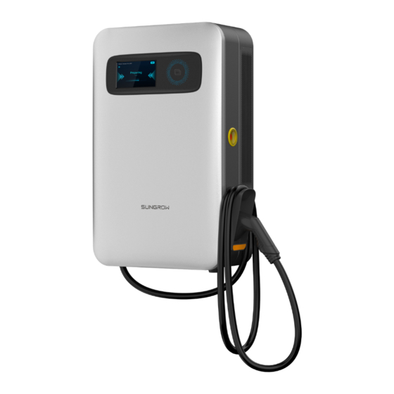
Product Introduction Introduction The 30kW DC charger (hereinafter “Charger”) is used for DC charging of electric vehicles (EVs) and can be wall-mounted, pole-mounted, or cart-mounted, with the following advantages: Technology leadership Adopting the world's leading power supply technology and design concept, the charger is designed to provide safe, reliable, and controllable DC power for electric vehicles. -
Page 14: Production Introduction
2 Product Introduction User Manual Production Introduction 2.2.1 Appearance and Dimensions figure 2-1 Product Dimensions (in mm) 2.2.2 Internal Structure figure 2-2 Diagram of the Internal Structure table 2-1 Internal Structure Description Name Door sensor Axial flow fan Insulation Monitor CCU(Charge Control Unit) module... -
Page 15: External Port
User Manual 2 Product Introduction Name DC Meter AC input connection terminal Charging connector TCU(Tariff and Control Unit) module Display Card Reader Lamp panel 2.2.3 External Port figure 2-3 Diagram of Bottom Terminals table 2-2 Description of Bottom Terminals Name DC charger cable outlet Air outlet RSVD port... -
Page 16: Led Indicator Signals
• Check the inner contents for damage after unpacking. Contact SUNGROW or the transport company in case of any damage or mismatches and provide photos to facilitate services. Do not dispose of the original packing case. It is recommended to store the device in original packing case when the device is decommissioned. -
Page 17: Packing List
User Manual 2 Product Introduction 2.3.2 Packing list figure 2-4 Packing list table 2-4 Packing list Name Unit Integrated single-connector DC charger IDC30E IDC30E wall-mounted weld assembly Positioning plate Handrail_M12... -
Page 18: Storage
2 Product Introduction User Manual Name Unit IDC30E socket-outlet trim IDC30E socket-outlet trim B Expansion bolt M1 card Wall-mounted components-upper left Wall-mounted components-upper right Wall-mounted components-lower left Wall-mounted components-lower right Montmorillonite desiccant Hexalobular socket pan head tamper proof screws M5X12, SUS304... -
Page 19: Installation
User Manual 2 Product Introduction • If the charger has been stored for more than a year, inspection and testing by professio- nals are required before it can be put into operation. Please store the charger according to the storage requirements. Product damage caused by failure to meet the storage requirements is not covered by the warranty. -
Page 20: Installation Tools
2 Product Introduction User Manual 2.4.2 Installation Tools figure 2-5 Tools table 2-5 Tools Name Working shoes Goggles Insulating gloves Earplugs... -
Page 21: Installation Clearance
User Manual 2 Product Introduction Name Dust proof mask Vacuum cleaner Marker Phillips screwdriver Level Measuring tape No.13 wrench, No.19 wrench French wrench Rubber hammer Electric drill Cable drilling tool: Ø12/Ø18 Pan head tamper proof wrench set Hydraulic clamp Hot air blower SIM card ejector pin 2.4.3 Installation Clearance Reserve ample clearance (see the following figure for details) on all sides of the charger to... -
Page 22: Pre-Installation Preparation
2 Product Introduction User Manual figure 2-6 Min. recommended installation clearance Do not block the air inlet and outlet of the charger, charger damage may occur if otherwise. 2.4.4 Pre-installation Preparation 2.4.4.1 RCD Requirements A residual current device (RCD) should be set between the charger and the grid. Please use an RCBO or an RCCB+MCB assembly. -
Page 23: Ac Input Cable
User Manual 2 Product Introduction 2.4.4.2 AC Input Cable The five-core copper-conductor cable is recommended if the AC-side transmission distance is less than 400m. It is suggested to use the cable with an outer diameter of 18-25mm, wires of which each has a cross-sectional area of 10mm 2.4.4.3 OT terminal To ensure the cable is securely connected to the wiring terminal, it is needed to crimp the corresponding terminal on the cable after leading the cable through the AC cable inlet. -
Page 24: Install Charger Brackets
2 Product Introduction User Manual Step 3 Put the expansion pipe with specification of M8*60mm into the hole; Step 4 Use expansion bolts to fix the bracket on the wall and tighten it with a French wrench; figure 2-7 Steps to drill holes - - End 2.4.5.2 Install Charger Brackets Step 1 Place the charger back-up on a foam or soft cloth to prevent damage to its casing;... -
Page 25: Charger Installation
User Manual 2 Product Introduction Step 3 Align the handles with the handles' installation hole and tighten them clockwise to secure them to the charger. figure 2-9 Handrail installation - - End 2.4.5.4 Charger Installation Step 1 Hold each handle with both hands and put the charger gently close to the wall bracket; Step 2 Align the bracket on the back of the charger with the position of the wall bracket and hang this accordingly from top to bottom. -
Page 26: Secure The Charger
2 Product Introduction User Manual Step 2 Align the keyhole plugs with the handles' installation holes and plug them back into the charger. figure 2-11 Installation of the keyhole plug - - End 2.4.5.6 Secure the Charger Step 1 Refer to the figure below, attach the charger to the wall bracket with M5*12 hexalobular sock- et pan head tamper proof screws, recommended torque ≤1.2N•m. -
Page 27: Connect The Cable Connection Terminal
User Manual 2 Product Introduction Step 4 Confirm that the connector socket is mounted firmly and then holster the charging connector into the charger's socket. figure 2-13 Installation of the connector socket table 2-7 Accessories to install the connector socket Quantity Name M5*12 hexalobular socket pan head tamper proof screws... - Page 28 2 Product Introduction User Manual Step 3 Select a heat-shrink tubing that matches the diameter of the wire, insert it to the terminal crimping position, and then tighten the heat-shrink tubing with a hot air blower; figure 2-14 Terminal crimping Step 4 The cable terminal is shown in the figure below.
- Page 29 User Manual 2 Product Introduction Step 6 Remove the waterproof connector from the AC cable inlet. Lead the crimped AC cable through the waterproof connector and into the AC cable inlet. Then, fit back the waterproof connector. Please make sure the insulation layer of the cable, where it is fastened by the waterproof connector, is intact.
-
Page 30: Ethernet Cable Connection
User Manual - - End 2.4.5.9 Ethernet Cable Connection If an Ethernet cable is used for accessing IDC30E to the network, proceed with the following steps. Step 1 Unscrew the sealing nut from the communication connector, and remove the sealing rubber washer inside. -
Page 31: Sim Card Installation
2.4.5.10 SIM Card Installation If a SIM card is used for accessing IDC30E to the network, proceed with the following steps. Step 1 Take out the SIM card tray from the TCU module using an ejector pin (needs to be prepared separately). -
Page 32: Pole Components
2-17 Pole Components table 2-8 Description of pole components Quantify Name Unit Pole weld assembly Pole back cover IDC30E pole components Pole top cover Pole top cover Hexalobular socket cheese head tamper proof screws Expansion bolt M12*110 Standard spring washer... -
Page 33: Foundation
User Manual 2 Product Introduction 2.4.6.2 Recommended Construction Scheme for Charger Foundation figure 2-18 Charger foundation diagram The n60 PVC conduit is embedded in the foundation, and the AC input cable passes through the PVC plastic conduit for subsequent connection with the inter- nal circuit of the charger. -
Page 34: Install The Mounting Pole
2 Product Introduction User Manual Step 3 Remove the set screws of the cover plate on the back of the charger and remove the back cover. figure 2-19 Remove the back-cover plate table 2-9 Accessories to remove the back-cover Quantity Name M5*14 hexalobular socket countersunk head screws M5*12 hexalobular socket pan head tamper proof screws... -
Page 35: Install The Handles
User Manual 2 Product Introduction Step 4 Use No.19 wrench to attach the pole to the foundation. figure 2-20 Pole installation - - End 2.4.6.5 Install the Handles For detailed installation information, please refer to "2.4.5 Wall-Mounted Installation". 2.4.6.6 Charger Installation Step 1 Hold the handles with both hands and lift the charger to the upper end of the pole;... -
Page 36: Detach The Handles
2 Product Introduction User Manual Step 3 Use M8*16 hexalobular socket pan head tamper proof screws to lock the charger with the pole and confirm that they are correct before use. figure 2-21 Charger installation table 2-10 Accessories to install the charger Quantity Name Positioning pin... -
Page 37: Connect The Ac Cable
User Manual 2 Product Introduction Step 4 Secure the orange plug with M4*12 hexalobular socket pan head screws. figure 2-22 Install the connector socket - - End 2.4.6.9 Connect the AC Cable Step 1 Open the charger cabinet door; Step 2 Lead the AC cable through the PVC plastic conduit embedded in the foundation and pole, and then connect to the charger. -
Page 38: Install The Cover Plate
2 Product Introduction User Manual 2.4.6.10 Install the Cover Plate Step 1 Connect the back-cover plate of the charger and secure it with M5*12 hexalobular socket countersunk head screws; Step 2 Close the base-cover plate and attach it to the pole with M5*14 hexalobular socket pan head tamper proof screws. -
Page 39: Movable Charger Installation (Optional)
User Manual 2 Product Introduction figure 2-25 The charger connector installation 2.4.7 Movable Charger Installation (Optional) Step 1 Fix the wall-mounting bracket to the cart with M8*16 bolt assemblies. Step 2 Place the charger on a flat surface covered with protective materials such as foam or a sponge mat. - Page 40 2 Product Introduction User Manual Step 4 Remove the keyhole plugs on the left and right sides of the charger, and keep them properly for later use. Fit the handles in the corresponding holes on both sides of the charger, and tighten them.
- Page 41 User Manual 2 Product Introduction Step 8 For detailed information of AC terminal connection, please refer to "2.4.5.8 Connect the Ca- ble Connection Terminal" Step 9 For detailed information of network connection, please refer to "2.4.5.10 SIM Card Installa- tion" "2.4.5.10 SIM Card Installation"...
-
Page 42: Interface Function Description
Interface Function Description Page Introduction 3.1.1 System Check When the charger is powered on for the first time, the program starts automatically. Step 1 Start the program to run a system check; Step 2 After 30 seconds, the touch screen enters the Start page. figure 3-1 System check page - - End 3.1.2 Start Page... -
Page 43: Other
User Manual 3 Interface Function Description figure 3-2 The start page If the charger is inactive for 5 minutes, the touch screen automatically enters into screen- saver mode and the backlight will be dimmed. You can touch the screen to unlock. figure 3-3 The Screen-saver Page 3.1.3 Other Pages In addition to the Start page, five other pages indicate different states of the charger: unavail-... -
Page 44: Unavailable
3 Interface Function Description User Manual 3.1.3.1 Unavailable When the charger is unavailable, the touch screen enters the Unavailable page. A warning icon and a prompt message are shown as below: figure 3-4 Unavailable If you plug the charging connector when the charger is unavailable, you cannot start the charging session and are prompted with a message that says the charging point is disabled. -
Page 45: Emergency Stop
User Manual 3 Interface Function Description figure 3-5 Charging Point is Disabled When the charger is available again and there are no other errors, plug the charging connec- tor into your car and the touch screen enters the Card Swiping page according to your set- ting (scan to charge or Plug&Play). - Page 46 3 Interface Function Description User Manual figure 3-7 Emergency Stop If you plug the charging connector during an emergency stop, you cannot start the charging session. figure 3-8 Emergency Stop Button Has Been Pressed When the charger is available again and there are no other errors, plug the charging connec- tor into your car and the touch screen enters the Card Swiping page according to your set- ting (scan to charge or Plug&Play).
-
Page 47: Firmware Update
User Manual 3 Interface Function Description figure 3-9 Card Swiping Page or Plug & Play 3.1.3.3 Firmware Update When the firmware is updating, the touch screen enters the Firmware Update page. An up- dating icon and a prompt message are shown as below. During updating, do not turn off the power or enter the operating mode. -
Page 48: Offline
3 Interface Function Description User Manual figure 3-11 Rebooting 3.1.3.4 Offline When the charger is offline, an icon is displayed on the upper right side of the page. The charger is offline because, the network is connected, but the OCPP platform cannot be connected (!); figure 3-12 Icon Displayed When There is a Network Connection the network is disconcerted, and the OCPP platform cannot be connected (\). -
Page 49: Language Settings
User Manual 3 Interface Function Description Step 2 The touch screen enters the Unavailable page. figure 3-14 A technical issue occurred When an error occurs, a warning icon indicating that the charger cannot be used appears in the touch screen. Step 3 Click or plug the charging connector directly. -
Page 50: Charging
3 Interface Function Description User Manual Step 3 Click the Confirm button to exit the Language Settings page. figure 3-15 Language Settings After switching languages, the language setting icon becomes the abbreviation of the first three letters of the corresponding language. The language of the page will be switched to the selected language. -
Page 51: Charging Method
User Manual 3 Interface Function Description Step 3 Plug the charging connector into your vehicle. figure 3-16 Your Vehicle Has Been Connected - - End 3.2.2 Charging Method 3.2.2.1 Charging via RFID Card Swipe Card When the charging connector is plugged into your car, the plugging icon is lit, and the touch screen enters the Card Swiping page. - Page 52 3 Interface Function Description User Manual • The card cannot be recognized. • The card is banned. • The card is expired. • The card is occupied. • Unknown error. • The card is not in the local list (only for offline mode). figure 3-18 Authentication /Authentication Successful In Preparation figure 3-19 Preparing...
- Page 53 User Manual 3 Interface Function Description • When the charging is interrupted during the preparation stage (such as unplug- ging the charging connector, malfunctioning, pressing the emergency button), the touch screen enters the Charging Finished page. • If the charging connector is unplugged in other situations, the touch screen en- ters the Start page.
- Page 54 3 Interface Function Description User Manual On the second screen, select on the right will display the status of the charger: • Charging power is limited by the charger • Charging power is limited by the vehicle • Charge at the maximum power If the charger is inactive for 5 minutes, the touch screen automatically enters screen-saver mode and the backlight will be dimmed.
- Page 55 User Manual 3 Interface Function Description If you swipe a different RFID card to stop charging, you will be prompted to use the previous RFID card. figure 3-22 Scan your card to stop charging/Use the previous RFID Card There is no stop button on the second screen, you can either return to the first screen or swipe the card to stop charging.
-
Page 56: Plug&Play
3 Interface Function Description User Manual figure 3-24 The Charging Finished Page 3.2.2.2 Plug&Play The overall charging process is different from that of Charging via RFID card in: • No RFID charge card. • When the charging connector is plugged into the vehicle, the touch screen enters the Preparing page •... - Page 57 User Manual 3 Interface Function Description figure 3-25 Preparing Stop charging: Stop the the charging session from the vehicle or the touch screen. Press button to stop. Complete charging: Unplug the connector to complete the charging. figure 3-26 Confirm to Stop Charging/ The Charging is Completed...
-
Page 58: Operation And Maintenance Mode
Operation and Maintenance Mode... -
Page 59: Login And Logout
Step 2 In the pop-up dialog box, enter the password 202207 and click figure 4-2 Password input box The password 202207 is for Read-only . If you need other authorities, please refer to "Operation and Maintenance Mode" or contact SUNGROW customer service. -
Page 60: Logout
4 Operation and Maintenance Mode User Manual - - End 4.1.2 Logout Click to return to the initial page. figure 4-3 Operation & Maintenance Page Function Description 4.2.1 CCU Info Select "CCU_Info" from the navigation bar to turn to the CCU_Info page. The CCU_Info page contains two pages: user page and administrator page. - Page 61 User Manual 4 Operation and Maintenance Mode figure 4-4 Administrator page The CCU_Info page mainly contains: • System status display column "System Data" • Real-time error information "Current Error info" • History error information "History Error info" • General Control "Setting&Control" •...
- Page 62 4 Operation and Maintenance Mode User Manual figure 4-5 Monitoring&System Data:CCU1 Setting&Control figure 4-6 Setting&Control Click to adjust the maximum current/power of the CCU; Click "Set" to set the CCU local charging current/voltage, and each CCU corresponds to the maximum current/power output by a connector;...
- Page 63 User Manual 4 Operation and Maintenance Mode General Control figure 4-7 General Control Current Error Info. Click "Current Error info" to display the real-time error information in the pop-up dialog box; Click "Close" to close the dialog box. History Error Info Click "History Error info"...
-
Page 64: Version
4 Operation and Maintenance Mode User Manual 4.2.2 Version figure 4-9 Administrator page The Version page mainly contains: • "Firmware Version" • "Update" Firmware Version figure 4-10 Firmware version Update Local update via USB drive is available in case that the Internet is unavailable. -
Page 65: Config_1
User Manual 4 Operation and Maintenance Mode figure 4-11 Update Insert the USB drive and store the description file of the new firmware and the corre- sponding firmware in the root directory; Click the "Target Device" drop-down menu to select target CCU/MDSP/SDSP/TCU ALL to be upgraded;... - Page 66 4 Operation and Maintenance Mode User Manual figure 4-12 Administrator page The Config_1 page mainly contains: • "Network Connection" • "Static information" • Custom configuration "Custom config" • Cloud Access Point "Websocket" • WIFI Name and Password "Existing SSID and password" •...
- Page 67 User Manual 4 Operation and Maintenance Mode Static Information figure 4-14 Static Information Displays charge point model, serial number, firmware version and charge point vendor. Custom Config figure 4-15 Custom config Displays network area charge mode, network mode, time zone and default language. Network Area: Public and Private.
- Page 68 4 Operation and Maintenance Mode User Manual Existing SSID and Password figure 4-17 Existing SSID and password Displays SSID list and content. Sim Card figure 4-18 Sim card Displays APN, PIN and iccid.
-
Page 69: Faults And Troubleshooting
Faults and Troubleshooting All fault codes are displayed in operation and maintenance mode. If the fault still persists after troubleshooting, please contact SUNGROW customer service. table 5-1 TCU faults and troubleshooting Displaying text Fault cause Solutions 1. Check the ethernet cable connection,... - Page 70 20 seconds, and turn it on again 4. If the problem persists, please contact SUNGROW Customer service 1. Charger is connected to the internet via wifi: a. check if the wifi router is working properly.
- Page 71 OCPP by the back end blocked back-end, but 2. If the server provider cannot provide the it is currently solutions, please contact SUNGROW Cus- blocked tomer service The RFID card 1. Contact with the OCPP back-end server is registered in...
- Page 72 OCPP back- and follows the instructions of the other er- end service rors in this table, please contact SUNGROW Customer service Unable to initiate charg- Reserved ing, replug and try again...
-
Page 73: Ccu
If it is, release the button has been pressed has been 2. If the problem persists, please contact pressed SUNGROW Customer service 1. Plug out the charging connector, re-plug it in the vehicle, and try to start a charging The charging session again... - Page 74 Temp_Alarm current. attention 2Err_Connector1_Insulation_Monitor_ Communication Check the commu- Communication_Failed_Alarm Failed. nication cable. Please contact The insulation monitor 3Err_Connector1_Insulation_Monitor_ SUNGROW Cus- Selfcheck_Device_Abnormal_Alarm selfcheck abnormal. tomer service. The insulation monitor Please contact 4Err_Connector1_Insulation_Monitor_ selfcheck wiring SUNGROW Cus- Selfcheck_Wiring_Abnormal_Alarm Abnormal. tomer service The insulation monitor...
-
Page 75: Llc
Output voltage ex- 2. Restart the charger and try ceeds the maximum EVT_LLC_A_OUTPUT_OV again. voltage 1000V 3. Please contact SUNGROW cus- tomer service. 1. Check the battery voltage of the vehicle Output voltage falls 2. Restart the charger and try... - Page 76 Output voltage falls vehicle EVT_LLC_B_ OUTPUT_ below the minimum 2. Restart charger and try again. voltage 200V 3. Please contact SUNGROW cus- tomer service. EVT_LLC_B_OUTPUT_OC 1. Check the wiring of DC+ and 2. Restart the charger and try EVT_LLC_B_OUTPUT_ again.
- Page 77 SOR_INVALID 1. Check the wiring of DC+ and DC-. 2. Restart the charger and try EVT_HARD_OCP Inrush current again. 3. Please contact SUNGROW cus- tomer service. 1. Restart the charger and try 1. Internal communi- again. EVT_SCI_TIMEOUT cation fault 2. Please contact SUNGROW cus- 2.
- Page 78 1. Turn off, waiting for 10 minutes 1. Internal overflow and then restart charger and try temperature EVT_HS2_OTP again. 2. Internal circuit 2. Please contact SUNGROW cus- fault" tomer service. 1. Check the input voltage whether between normal range 1. Internal system voltage exceed nor- 2.
-
Page 79: Pfc
Faults cause Solutions 1. Check the wiring of DC+ and EVT_HARD_OUTPUT_ 2. Restart the charger and try Overcurrent SHORT again. 3. Please contact SUNGROW cus- tomer service. Software version is EVT_HARD_VERSION_ Please contact SUNGROW cus- not compatible ERROR tomer service. - Page 80 AmbientTempHgih 1. Turn off, waiting for 10 mi- nutes and then Restart the RadiatorATempHgih High internal charger and try again. RadiatorBTempHgih temperature 2. Please contact SUNGROW RadiatorCTempHgih customer service. BUSPreChargeVolLow 1. Restart the charger and try PBUSPreChargeVolLow again. Internal fault NBUSPreChargeVolLow 2.
- Page 81 5 Faults and Troubleshooting Errors names Fault cause Solutions 1. Restart the charger and try again. SWUVPFault Internal fault 2. Please contact SUNGROW customer service. Software version is not Please contact SUNGROW LLCVersionNotMatch compatible customer service. GridAVolHigh 1. Check the AC input voltage...
- Page 82 Fault cause Solutions BUSVoltageContinueHigh PBUSVoltageContinueHigh NBUSVoltageContinueHigh BUSVoltageDiscreteHigh 1. Restart the charger and try PBUSVoltageDiscreteHigh again. Internal fault NBUSVoltageDiscreteHigh 2. Please contact SUNGROW customer service. BusRippleOver PBusRippleOver NBusRippleOver InPutCurrUnbal Fan1Speedabnormal 1. Restart the charger and try Fan2Speedabnormal again. Fan3Speedabnormal Internal fan fault 2.
-
Page 83: Charging Stop Code
1. vehicle forcefully 3. If the problem still persists, please contact SUNGROW customer service The PWM is invalid Please contact SUNGROW PWM_Failure PWM failure on the CP-PE... - Page 84 SDP process failed Failure step 1. 3. If the problem still persists, please contact SUNGROW customer service" 1. Plug out the charging con- nector, re-plug it in the vehicle, and try to restarting a charging...
- Page 85 (DIN/ Failure step 1. ISO15118) failed 3. If the problem still persists, please contact SUNGROW customer service. 1. Plug out the charging con- nector, re-plug it in the vehicle, and try to restarting a charging session again...
- Page 86 Fault start the charger, and repeat process failed step 1. 3. If the problem still persists, please contact SUNGROW customer service. 1. Plug out the charging con- nector, re-plug it in the vehicle, and try to restarting a charging session again...
- Page 87 Abnormal abnormal step 1. 3. If the problem still persists, please contact SUNGROW customer service. 1. Check the output voltage on the vehicle or the charger dur- ing the charging session, if the voltage is over 1020V, the charging will not be successful.
- Page 88 195V, the charging will not be successful. In this case, plese contact SUNGROW customer service and do not proceed the next DC output voltage steps DC output...
- Page 89 1. hicle failed to send 3. If the problem still persists, message please contact SUNGROW customer service. 1. Plug out the charging con- nector, re-plug it in the vehicle, The communica- and try to restarting a charging...
-
Page 90: Maintenance Instructions
Maintenance Instructions Regular maintenance of the charger will ensure its service life and optimal efficiency. Mainte- nance personnel shall be responsible for the maintenance period and cycle according to the actual situation. The recommended maintenance cycle is once every six months. If any mal- function occurs, correct it in time. - Page 91 User Manual 6 Maintenance Instructions • Click the screen to operate and check whether the touch function is normal. • Check the waterproof performance around the screen and the plastic panel. • Check whether there is foreign object inside the fan and the fan openings. Clean the dust with water to prevent the accumulation dust from affecting the heat dissipation.
-
Page 92: Appendix
Appendix System Parameters table 7-1 System parameters Type designation Parameter IDC30E Input voltage 400 Vac±10% Nominal frequency 50 Hz Input (AC) Max. input current 52 A Input cable specification 5*10 mm Power input 3P+N+PE DC output power 30 kW 200~1000 Vdc, 375~1000 Vdc (At... -
Page 93: Quality Assurance
• The customer shall give SUNGROW a reasonable period to repair the faulty device. Exclusion of Liability In the following circumstances, SUNGROW has the right to refuse to honor the quality guarantee: • The voltage ratings used by the customers must meet the requirements of the charger. -
Page 94: Contact Information
Damage caused by abnormal natural environment or man-made damage. If the product fault arises due to any of the above causes and the customer requires repair services, such a service may be provided at a cost, following the assessment of SUNGROW. Software Authorization The company is not liable for any loss caused by the software products provided with the products. - Page 95 Sungrow Power Supply Co., Ltd. www.sungrowpower.com...
Need help?
Do you have a question about the IDC30E and is the answer not in the manual?
Questions and answers