Advertisement
Quick Links
Advertisement

Related Manuals for Sungrow SR20D-M


Summary of Contents for Sungrow SR20D-M
- Page 1 Rvjdl!Jotubmmbujpo!Hvjef QW!Sbqje!Tivuepxo!Frvjqnfou SR20D-M SR20D-M-QIMUL-Ver13-202408...
- Page 2 Failure to follow any of the above requirements may lead to personal injury or damage to the device. Tbgfuz!Jotusvdujpot SUNGROW shall not be held liable for any personal injury or device damage caused by violation of the operation instructions in this guide and the user manual.
- Page 3 Signs on the Product Lethal high voltage! Hot surface with a temperature that may Only professional and qualified personnel are allowed to exceed 60 ℃. Risk of burns! install and operate the RSD! Equipment protected by double insulation Comply with RCM certification. or reinforced insulation.
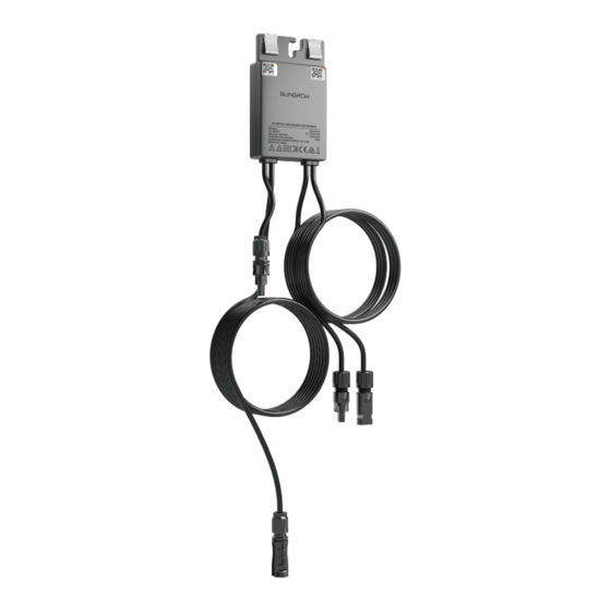
- Page 4 Qspevdu!Jouspevdujpo 27mm 86mm 143mm 200mm 2950mm 1400mm Jotubmmbujpo!Tjuf 85 - (+185°F) -40 - (-40°F) 0-100 % Jotubmmbujpo!Uppmt Nvmujnfufs: ≥1100 Vdc Qspufdujwf!hmpwft Jotvmbufe!tipft Xjsf!dvuufs 580.0 Ubqf!nfbtvsf Vujmjuz!lojgf Dsjnqjoh!uppm Xjsf!tusjqqfst Pqfo.foe!xsfodi!lju Tpdlfu!xsfodi;!N9...
- Page 5 Jotubmmbujpo!Tdfobsjpt Before installation, decide the installation and arrangement schemes based on the actual situation, to ensure that the RSD can be connected to PV modules and adjacent RSDs normally. Dbtf!2;!Npvoufe!po!QW!npevmf!)Dmjq.po* <400mm Jowfsufs 2348mm 1030mm Dbtf!3;!Npvoufe!po!hvjef!sbjm! Jowfsufs Opujdf The mounting and wiring should be performed in compliance with local laws, regulations, safety standards, and installation specifications.
- Page 6 Fyufotjpo!Dbcmf!Qsfqbsbujpo When connecting the RSD, if the distance between the connectors is too long, you will need to prepare an extension cable. 4 - 6 mm ø 6 - 9 mm 7-8mm ≥7 2.5-3 N m Dmjdl Dmjdl Xbsojoh !!!!When preparing an extension cable, pay attention to the selection of DC connectors at the two ends of the ...
- Page 7 Npvoufe!po!QW!npevmf!)Dmjq.po* Fotvsf!uibu!uif!STE!jt!jotubmmfe!gbdjoh!uif!cbdl!pg!uif!npevmf/!Puifsxjtf-!uif!dmjqt!nbz!cf!ebnbhfe/ Ep!opu!bqqmz!gpsdf!up!uif!STE!jo!b!ejsfdujpo!wfsujdbm!up!jut!dmjqt!xifo!dmjqqjoh!uif!STE!poup!uif!npevmf/! Puifsxjtf-!uif!dmjqt!nbz!cf!ebnbhfe/ Ep!opu!dmjq!uif!STE!joup!ipmft!jo!uif!npevmf!gsbnf!evsjoh!jotubmmbujpo/!Puifsxjtf-!zpv!nbz!opu!cf!bcmf!up!sfnpwf! uif!STE!bhbjo!boe!jut!dmjqt!nbz!cf!ebnbhfe/ Ep!opu!gpsdjcmz!cfoe!jut!dmjqt!xifo!dmjqqjoh!uif!STE!poup!uif!npevmf/!Puifsxjtf-!uif!dmjqt!nbz!cf!ebnbhfe/ Ju!jt!sfdpnnfoefe!up!jotubmm!STEt!po!uif!tbnf!tjef!pg!npevmft/ Ep!opu!dmjq!boe!sfnpwf!uif!STE!sfqfbufemz/!Puifsxjtf-!uif!dmjqt!nbz!cfdpnf!mpptf!boe!uivt!dboopu! gvodujpo!qspqfsmz/ Npvoufe!po!bmvnjovn!hvjef!sbjm Vtf!N9々36!U.ifbe!cpmu )opu!jodmvefe!jo!uif!tdpqf!pg!efmjwfsz* 5.0N m Npvoufe!po!tuffm!hvjef!sbjm!)U.ifbe!cpmu* Vtf!N9々36!U.ifbe!cpmu 5.0N m )opu!jodmvefe!jo!uif!tdpqf!pg!efmjwfsz*...
- Page 8 Npvoufe!po!tuffm!hvjef!sbjm!)cpmu!bttfncmz* 5.0N m Vtf!N9々36!cpmu!bttfncmz )opu!jodmvefe!jo!uif!tdpqf!pg!efmjwfsz* Xbsojoh During installation, make sure the metal clips do not get in contact with the bracket. Install the RSD with its back tightly against the bracket. Installing it from the opposite direction may damage the RSD and such damage will not be covered by warranty.
- Page 9 Opujdf Complete the RSD wiring and measure the output voltage by following the steps below. When there is an odd number of PV modules, it is allowed to connect one single module to an RSD. After completing the wiring of an RSD, use a multimeter to measure its output voltage. Ensure that the ...
- Page 10 Do not coil the RSD's cable when wiring, given that the communication quality may decline if the extension cable is too long. The maximum communication distance between the inverter and the RSD should be less than 350m. If the distance exceeds 350m, consult SUNGROW first. PVU. PVU. PVU, PVU.
- Page 11 <350m Xbsojoh DC wiring requirements: The positive and negative DC cables of the same PV string should be kept parallel and close to each other. The correct wiring is shown below. Tdfobsjp!2 QW. QW, Tdfobsjp!3...
- Page 12 Xbsojoh The positive and negative DC cables of the same PV string are not allowed to be routed apart separately, as shown in the figure below. QW. QW,...
- Page 13 Dpnnjttjpojoh Complete the settings for the RSD on the iSolarCloud App. For detailed iSolarCloud App instructions, see the user manual for the iSolarCloud App.
- Page 14 Gps!npsf!qspevdu!jogpsnbujpo!jo!uif!RS!dpef! !!!ps!bu! iuuq;00tvqqpsu/tvohspxqpxfs/dpn0...
Need help?
Do you have a question about the SR20D-M and is the answer not in the manual?
Questions and answers