Sungrow AC011E-01 User Manual
Ac charger
Hide thumbs
Also See for AC011E-01:
- User manual (60 pages) ,
- Quick installation manual (9 pages) ,
- User manual (44 pages)

Related Manuals for Sungrow AC011E-01


Summary of Contents for Sungrow AC011E-01
- Page 1 AC Charger User Manual AC011E-01 AC011E-01AC ChargerUser ManualAC011E-01- UCN-Ver11-202203 AC011E-01-UCN-Ver11-202203...
-
Page 3: All Rights Reserved
Software Licenses • It is prohibited to use data contained in firmware or software developed by SUNGROW, in part or in full, for commercial purposes by any means. • It is prohibited to perform reverse engineering, cracking, or any other operations that compromise the original program design of the software developed by SUNGROW. -
Page 4: About This Manual
Please read this manual carefully before using the product and keep it properly at a place for easy access. All contents, pictures, marks, and symbols in this manual are owned by SUNGROW. No part of this document may be reprinted by the non-internal staff of SUNGROW without written authorization. - Page 5 Indicates high-risk potential hazards that, if not avoided, may lead to death or ser- ious injury. Indicates moderate-risk potential hazards that, if not avoided, may lead to death or serious injury. Indicates low-risk potential hazards that, if not avoided, may lead to minor or mod- erate injury.
-
Page 7: Table Of Contents
Contents All Rights Reserved .....................I About This Manual......................II 1 Introduction .......................1 1.1 Introduction ....................1 1.2 Model and Nameplate ..................1 1.3 Scope of Delivery ...................1 1.4 Appearance and Dimensions................2 1.5 RFID card ......................2 1.6 Indicator ......................3 1.7 Port .......................3 1.8 System Topology ....................4 2 Installation ......................5 2.1 Installation Requirements................5... -
Page 9: Introduction
Introduction Introduction The three phase AC charger is used for electric vehicle’s AC charging, with the function of charging by scanning the RFID card. The RFID card is a key component to start or stop the charging session. The LED indicator on the front panel helps you understand what is happening with the charger by indicating different colors. -
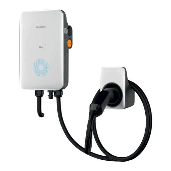
Page 10: Appearance And Dimensions
1 Introduction User Manual Wall-mounted bracket assembly with packaging material R-50 desiccant Warranty Card & Certificate of Conformity User Manual L-shaped wrench M1 card × 2 Appearance and Dimensions figure 1-1 Appearance and dimensions RFID card One card only for one pile, off line card, swiping the card to start and stop, no billing function Each charger has 2 cards Parameter Dimensions: 85.6×... -
Page 11: Indicator
User Manual 1 Introduction Indicator table 1-1 Indicator Status Charging Station Status Indicator Effect Remarks Standby Blue indicator flashes slowly, on for 1s and Normal off for 4s; circulating Charging (S2 is closed and Blue indicator breathes, on for 1s and off for Normal current is normal) 1s;... -
Page 12: System Topology
1 Introduction User Manual System Topology figure 1-3 System topology diagram... -
Page 13: Installation
Installation Respect all local standards and requirements during mechanical installation. Installation Requirements Location Requirements Select an optimal mounting location for safe operation, long service life and expected performance. • The charger with protect IP65 can be installed both indoors and outdoors. •... - Page 14 2 Installation User Manual Carrier Requirements The concrete wall should be capable of withstanding a force of four times the weight of the charger and be suitable for the dimensions of the charger. The installation carrier should meet the following requirements: Angle Requirements Install the charger vertically.
-
Page 15: Unpacking And Inspection
User Manual 2 Installation Unpacking and Inspection table 2-1 Label Descriptions Item Name Quantity Charger Socket-outlet Back plate Upper hanging plate Lower hanging plate Pile (optional) Combination screw, expansion screw 4, 7 (wall-mounted); 11, 0 (pile- mounted) L-shaped spanner... -
Page 16: Installation Tools
2 Installation User Manual Installation Tools table 2-2 Label Descriptions Item Name Specification Marker pen Wire stripper Cable drilling tool Ø6, Ø12 Cross screwdriver M3, M4 Hydraulic clamp 2.5-6mm Hot air gun Crystal crimping pliers Adjustable spanner Cable Connection Circuit diagram... - Page 17 User Manual 2 Installation figure 2-1 Circuit diagram table 2-3 Label Descriptions Label Description LED indicator board, showing the status of the charger RS485, reserved for external communication ESP32 module for Bluetooth/Wifi communication CT for leakage current detection Charging gun output (connected to target EV) CCU internal relay 25A/400V 30mA A RCD input cable 2.5mm The charger equipment is in the dotted box.
- Page 18 2 Installation User Manual The recommended cable specifications: 5×2.5 mm step 3 Adjust the cable to a suitable length, peel off the outermost insulation skin of the cable, and make the cable connection terminal. Remove the insulation skin at the end of each sub-cable; Insert the copper core of the stripped end of the cable into the cable hole of the copper lug;...
- Page 19 User Manual 2 Installation step 4 Connect the crimped terminals (OT2.5-5) to the corresponding terminals in turn and tighten them with a screwdriver. Recommended torque: 3±0.2 N·m. step 5 Connect the back cover and tighten the screws. - - End...
-
Page 20: 2.4.1 Communication Terminal
2 Installation User Manual 2.4.1 Communication terminal figure 2-2 RJ45 terminal components step 1 Crimp communication terminal port. step 2 Connect to an inverter or other communication device. - - End Crimp the blue wire and the blue-white wire to the crystal head. The blue line(PIN4) connects to 485B, and the blue-white line(PIN5) connects to 485A. - Page 21 User Manual 2 Installation The load-bearing capacity of the installation carrier is at least 4.5 times the weight of the charger. step 1 Install the backplate. Put the backplane in the installation position and mark the hole with a marker; Use a cable drilling tool to drill at the marked position;...
- Page 22 2 Installation User Manual Place the socket-outlet on the wall, tighten the screws with a screwdriver, and secure the socket-outlet. It is recommended that the socket-outlet be installed at the lower right side of the charger, with a linear distance of about 20cm from the charger. The actual situa- tion on site shall prevail.
- Page 23 User Manual 2 Installation Hold the charger with both hands to make it parallel to the wall surface, and buckle the upper hanging plate and the lower hanging plate on the back plate. The buckle between the hanging plate and the back plate is fastened with screws. The recommended torque is 1.2±0.1N ·...
-
Page 24: Pile Installation
2 Installation User Manual - - End Wall-mounted installation Pile Installation The pile is recommended to be installed on the concrete floor. If conditions do not permit, please install the foundation first, and then install the pile. Foundation Installation... - Page 25 User Manual 2 Installation Build the foundation according to requirements, it is recommended that the base is 100mm above the ground, the outer dimensions of the front, rear, left, and right side columns are greater than 100mm, and outlet holes are reserved. figure 2-3 Front view、side view(unit:mm)...
- Page 26 2 Installation User Manual Place the pile on a smooth horizontal surface and record the position of the surrounding mounting holes with a marker. Use a cable drilling tool to drill holes in sequence according to the marked positions, and the drilling depth is about 45mm.
- Page 27 User Manual 2 Installation Place the charger back side up on an object that is difficult to scratch the surface of the charger, and use a screwdriver to fasten the upper and lower hanging plates on the charger; Make sure that the upper hanging plate and the lower hanging plate are firmly installed; Lift the charger with both hands to the back plate of the pile and make it parallel to the pile.
- Page 28 2 Installation User Manual...
-
Page 29: Charging Operation
Charging Operation Connect Charger to EV Park EV near to the charger, and plug its guns into the EV. After plug-in, please check if the gun is correctly and tightly connected. With appropriate connection, the charger LED indica- tor will change to flashing blue light, which indicates that the charger is ready for charging. Start Charging &... -
Page 30: Power-On Checking
Power-on Checking Check before Power-on Please check the followings before any operation: The charger’s location is easy for operation and repairing. Double confirm the charger is installed properly. AC input’s current leakage protection switch is reasonable. No other stuff or component left on the top of the charger. Power-on Charger Make sure all checking is done according to the above items. -
Page 31: Faults And Troubleshooting
The grid voltage is still if the grid voltage is above above 254V after 254V. overvoltage. Contact Sungrow Customer Service preceding causes are ruled out and the fault persists. Generally, the charger fault will be removed automatically after the grid returns to normal. If the... - Page 32 EV ab- after-sales service of EV normal manufacturer; Overcur- Output current is above 17.6A rent fault Stop charging and pull out the charging gun. If the charger is still in fault status, please contact Sungrow Cus- tomer Service;...
- Page 33 Power off the device and restart. Charg- circuit Try to recharge. If the fault occurs er ab- RCD circuit is abnormal. fault repeatedly, contact SUNGROW normal Customer Service. Relay The temperature of the main overtem- relay is too high, it may be a...
- Page 34 5 Faults and troubleshooting User Manual Charger Status Indicator Effect Remarks Red indicator is on for 0.5s, off for 0.5s, flashes twice Ground warning Abnormal and then off for 3s; circulating Red indicator is on for 0.5s, off for 0.5s, flashes three Output short Abnormal times and then off for 3s;...
-
Page 35: Appendix
Appendix System Parameters table 6-1 System Parameters Specifications Parameter AC011E-01 Housing Material Wall-mount (default), Floor-stand (optional) Installation method Routing method Bottom-in and bottom-out 205×310×92mm(W×H×D) Product Dimension Appearance Weight 3.8 kg Structure Cable length Socket-output 71cm (Floor-stand) height Charging Type 2 Euro charging gun... -
Page 36: Quality Assurance
• The customer shall give SUNGROW a reasonable period to repair the faulty device. Exclusion of Liability In the following circumstances, SUNGROW has the right to refuse to honor the quality guarantee: • The free warranty period for the whole machine/components has expired. -
Page 37: Eu Declaration Of Conformity
The fault or damage is caused by installation, repairs, modification, or disassembly per- formed by a service provider or personnel not from SUNGROW. • The fault or damage is caused by the use of non-standard or non-SUNGROW compo- nents or software. •... - Page 38 Sungrow Power Supply Co., Ltd. Add: No.1699 Xiyou Rd.,New & High Technology Industrial Development Zone, 230088,Hefei, P. R. China. Web: www.sungrowpower.com E-mail: info@sungrow.cn Tel: +86 551 6532 7834 / 6532 7845 Specifications are subject to changes without advance notice.
Need help?
Do you have a question about the AC011E-01 and is the answer not in the manual?
Questions and answers