Sungrow AC011E-01 User Manual
Ac charger
Hide thumbs
Also See for AC011E-01:
- User manual (53 pages) ,
- Quick installation manual (9 pages) ,
- User manual (44 pages)

Related Manuals for Sungrow AC011E-01


Summary of Contents for Sungrow AC011E-01
- Page 1 User Manual AC Charger AC011E-01 / AC011E-01 L1 AC011E-01 / AC011E-01 L1AC ChargerUser ManualAC011E-01-UEN-Ver14- 202309 AC011E-01-UEN-Ver14-202309...
-
Page 3: All Rights Reserved
Software Licenses • It is prohibited to use data contained in firmware or software developed by SUNGROW, in part or in full, for commercial purposes by any means. • It is prohibited to perform reverse engineering, cracking, or any other operations that compromise the original program design of the software developed by SUNGROW. -
Page 4: About This Manual
Please read this manual carefully before using the product and keep it properly in a place for easy access. All contents, pictures, marks, and symbols in this manual are owned by SUNGROW. No part of this document may be reprinted by the non-internal staff of SUNGROW without written authorization. - Page 5 Indicates moderate-risk potential hazards that, if not avoided, may lead to death or serious injury. Indicates low-risk potential hazards that, if not avoided, may lead to minor or mod- erate injury. Indicates potential risks that, if not avoided, may lead to device malfunctions or fi- nancial losses.
-
Page 7: Table Of Contents
Contents All Rights Reserved .....................I About This Manual......................II 1 Product Overview .....................1 1.1 Introduction ....................1 1.2 Appearance and Dimensions................1 1.3 LED Signals ....................4 1.4 System Overview ...................5 1.5 Load Management..................7 2 Installation ......................8 2.1 Installation Requirements................8 2.2 Unpacking and Inspection ................9 2.3 Installation Tools................... - Page 8 5.5.1 Charging Bills ..................36 5.5.2 Scheduled Charging................37 5.5.3 Customer Service ................38 5.5.4 Network Settings.................39 5.5.5 Firmware Management................40 5.5.6 Device Connection ................41 5.5.7 Charge Cards ..................41 5.5.8 Settings....................42 6 Troubleshooting ....................44 7 Appendix ......................48 7.1 Technical Data .....................48 7.2 Additional Information ...................50 7.3 Quality Assurance ..................50 7.4 Contact Information ..................51...
-
Page 9: Product Overview
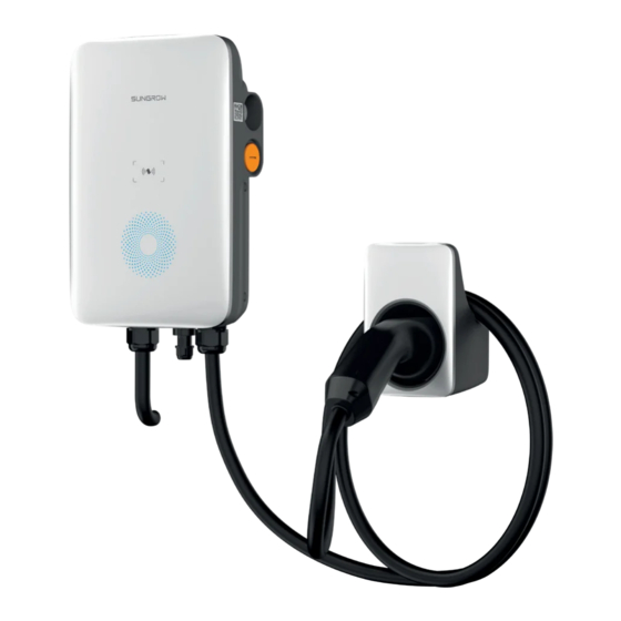
Product Overview Introduction The AC011E-01 charger (hereinafter referred as "charger" or "AC-Charger") is used for AC charging of electric vehicles (BEV/PHEV) and can be either wall-mounted or pole-mounted, with the following advantages. Ease of Use EV drivers can start and stop charging via RFID card, iSolarCloud or iEnergyCharge. When the vehicle is fully charged, the charging will stop. - Page 10 1 Product Overview User Manual Model Nameplate Description Position Note AC Charger Nominal power (kW) European standard Screen configuration • 0: without screen M1 card configuration • 1: with card Version (Optional) • Default: version for usage together with SHRT for 3-phase combo-solution •...
- Page 11 User Manual 1 Product Overview Electrical Connection Ports figure 1-1 Ports table 1-1 Label Explanation Position Description Charging cable output (pre-assembled with charging cable) RS485 communication interface (SHRT connection) AC input (AC connection)
-
Page 12: Led Signals
1 Product Overview User Manual Dimensions figure 1-2 Dimensions (in mm) LED Signals table 1-2 LED Signals LED Signal Description Standby mode The blue LED blinks slowly (on for 1 s and off for 4 s) Vehicle charging The blue LED blinks (on for 1 s and off for 1 s) Charging ended The blue LED is glowing Vehicle plugged in... -
Page 13: System Overview
In both charging scenarios, with standard and advanced version, smart charging visualization via App is possible. In addition to charging from the grid, the ad- vanced versions support intelligent energy consumption usage in combination with SUNGROW's 3-phase combo solution. Stand-alone EV Charger figure 1-3 System topology diagram of EV charger... - Page 14 Protected house loads directly connected to the Backup loads inverter. Non-protected house loads. They will be discon- Normal loads nected in case of grid failure. AC-Charger AC011E-01 For SUNGROW's solar-storage-EV charging solution, please refer to the user manual of related inverter. See "7.2 Additional Information".
-
Page 15: Load Management
A smart energy meter that monitors power usage DTSU666 Smart En- and helps to avoid power outages caused by ergy Meter (optional) peak electricity during home charging. Utility grid TT, TN-C, TN-S, TN-C-S. Energy consumed by home appliances. House loads Charger AC011E-01 L1... -
Page 16: Installation
Installation Respect all local standards and requirements during mechanical installation. Any damage or malfunction with the charger caused by negligence or improper use will not be eligible for service and replacement under the warranty. Installation Requirements Location Requirements Select an optimal mounting location for safe operation, long service life and expected performance. -
Page 17: Unpacking And Inspection
After receiving the product, check whether the appearance and structural parts of the device are damaged, and check whether the packing list is consistent with the actual ordered product. If there are problems, do not install the device and contact your distributor first. If the problem persists, contact SUNGROW in time. - Page 18 2 Installation User Manual table 2-1 Label Descriptions Item Name Quantity AC-Charger Charging cable bracket Backplate Upper mounting plate Lower mounting plate Mounting pole (optional) Combination screw and expansion 4, 7 (wall-mounted); 11, 0 (pole- screw mounted)
-
Page 19: Installation Tools
User Manual 2 Installation Item Name Quantity L-shaped spanner Wire end ferrule Countersunk screw RJ45 screw connector DTSU666 Smart Energy Meter (optional) RFID card Quick Installation Guide, Warranty 1, 1, 1 Card, and Certificate of Conformity The scope of delivery does not include the optional mounting pole (F) and energy meter (K). -
Page 20: Electrical Connection
2 Installation User Manual Item Name Specification Heat gun RJ45 crimping tool Hydraulic plier 2.5-6 mm Adjustable spanner Electrical Connection 2.4.1 Circuit Diagram figure 2-1 Circuit diagram table 2-3 Label Descriptions Label Description The LED lights that indicates the status of the charger RS485, reserved for external communication ESP32 module for Wi-Fi communication CT for leakage current detection... -
Page 21: Ac Cable Connection
User Manual 2 Installation The charger already integrates a DC residual-current device with a rated residual current of 6 mA. However, the charger also requires a type A RCD of 30 mA. Each charger in the system must be individually connected to the utility grid through an RCD and a miniature circuit breaker. - Page 22 2 Installation User Manual Step 4 Adjust the cable to a suitable length, and strip off the insulation of the cable to prepare for ca- ble connection terminals. Strip off the insulation from the end of each wire. Insert the copper core of the stripped end of the wire into the copper lug. Tighten the copper lug using a hydraulic plier.
-
Page 23: Rs485 Communication Connection
2.4.3 RS485 Communication Connection • For the Residential Hybrid + AC Charging Solution, the RS485 communication connection is needed to connect the AC Charger to SUNGROW's 3-phase in- verter (SHRT). • To connect the charger to a energy meter, see the related user manual. - Page 24 2 Installation User Manual Step 1 Crimp both ends of the Ethernet cable using a crimping tool. You will receive one of the following two RJ45 terminal components, please refer to the actual product you receive. figure 2-2 RJ45 screw connector(A) figure 2-3 RJ45 screw connector(B) Ensure that the blue wire and the blue-white wire is correctly crimped.
-
Page 25: Wall-Mounted Installation
Step 3 Install seals for the Ethernet cable in sequence. Ensure that the cable is secured. Step 4 Connect the charger to a Smart Energy Meter or a SUNGROW Hybrid inverter. figure 2-4 Connect to a Smart Energy Meter figure 2-5 Connect to an inverter(SHRT) - Page 26 2 Installation User Manual Step 1 Install the backplate. Hold the backplate in the desired position on the wall and mark the positions of the drill holes. Before drilling the hole for the backplate, locate and avoid water pipes and elec- trical wires in the wall.
- Page 27 User Manual 2 Installation Step 2 Install the charging cable bracket. Hold the charging cable bracket in the desired position on the wall and mark the posi- tions of the drill holes. Drill holes at the marked positions using a hammer drill. Insert the dowel into the hole.
- Page 28 2 Installation User Manual Step 3 Mount the charger. Secure the upper mounting plate and the lower mounting plate on the back of the charg- er using a screwdriver. (Torque: 1.2 ± 0.1 N·m) Hang the charger onto the backplate. Secure the upper and lower mounting plates to the backplate with screws.
-
Page 29: Pole-Mounted Installation
User Manual 2 Installation figure 2-6 Wall-mounted charger Pole-Mounted Installation It is recommended to install the pole on a solid support surface (such as concrete or tarmac). If conditions do not permit, install the foundation first, and then install the mounting pole. 2.6.1 Foundation Installation The base should be 100 mm above the ground, and the exterior dimensions of the front, back, left, and right side columns should be greater than 100 mm. -
Page 30: Pole Installation
2 Installation User Manual figure 2-7 Front view and top view (unit: mm) 2.6.2 Pole Installation Step 1 Connect the AC cable. Remove the cover plate on the back of the pole using a cross screwdriver. Lead the AC cable through the bottom into the pole. Grab the AC cable when it reaches the cover plate and take out the end of the cable from the AC cable outlet. - Page 31 User Manual 2 Installation Step 2 Mount the charger. Place the pole on a solid and flat surface, and mark the positions of the drill holes. Drill holes at the marked positions using a hammer drill. (Diameter: 12 mm; depth: 70 Insert the dowel into the holes.
- Page 32 2 Installation User Manual Step 4 Install the upper mounting plate and lower mounting plate. Place the charger face-down on a clean and flat surface, and secure the upper and low- er mounting plates to the pole using a screwdriver. Ensure that the upper mounting plate and the lower mounting plate are firmly installed.
- Page 33 User Manual 2 Installation figure 2-8 Pole-mounted charger...
-
Page 34: Inspection Before Commissioning
Inspection before Commissioning table 3-1 Requirements before commissioning Description Item The charger is correctly mounted at a place that is convenient Location for operation and maintenance. Charger The charger is firmly and securely installed. Cables are correctly and firmly connected, and are adequately Cable protected from damage. -
Page 35: Commissioning Via Isolarcloud
Commissioning via iSolarCloud This section only applies to use cases with the advanced version of the charger. For commissioning procedure, refer to the user manual of related inverter. See "7.2 Addition- Information". -
Page 36: Ienergycharge App
iEnergyCharge App iEnergyCharge App is a tool that allows users to operate and manage their EV chargers. Users can complete account settings and charger configuration, manage charge cards, operate the charger, and reach customer service on the App. Depending on the version of iEnergyCharge you are using, the user interface might be slightly different. -
Page 37: Add A Charger
User Manual 5 iEnergyCharge App - - End Add a Charger To add a charger to your account on the iEnergyCharge App for operation and management, you need to set up a reliable network connection between the devices first. Requirements: •... - Page 38 5 iEnergyCharge App User Manual Step 3 Go to WLAN settings on your mobile device, and connect to the charger's WLAN. The charg- er's WLAN is named as its S/N, and the password is "admin123" or no password required. Step 4 Once connected successfully, go back to the App and enter the login password, which should be “SGC666”, or “the 4-digit PIN code”...
- Page 39 If the charging mode is set to “EMS”, you need to enter the password, which is the 4-digit PIN code on the RFID card. Default server address: wss://europe.suncharger.cn:20038. If you want to add a non-SUNGROW charger, enter the server address provided by the operator.
-
Page 40: Charging View
5 iEnergyCharge App User Manual Step 6 Connect the charger to a stable WLAN network, where you are required to enter the correct password. Step 7 After network connection is established successfully, tap Add device. The device is now added to your account successfully. Then, tap Complete, and you will be directed to the App's Home screen. -
Page 41: Start/Stop Charging
User Manual 5 iEnergyCharge App 5.4.1 Start/Stop Charging Start Charging Tap Start on the charging screen to start a charging session. During the charging process, you can view the real-time charging current and voltage, charging time, and battery status. Stop Charging If needed, you can tap Stop on the charging screen to stop charging immediately. - Page 42 5 iEnergyCharge App User Manual Delete device Tap Delete device at the bottom of the screen to delete the current charger. Charging history Tap Charging history to view the records of charging history. Offline charging Requirements: • Your phone and the charger have connection to the Internet. •...
- Page 43 Tap Load balancing. Set the “Monitoring method” to Smart Meter, and set the “Meter Type” and “Max. Home Load Current” based on the actual situation. Then, tap Set to effect the settings. Load balancing is available only for SUNGROW energy meters. Contact the cus- tomer service for more details.
-
Page 44: Account
5 iEnergyCharge App User Manual Firmware upgrade Requirements: • Your phone and the charger have connection to the Internet. • The charger is available. • There is a new version of the firmware. Tap Firmware upgrade. Tap Update to start remote firmware upgrade. To ensure proper functionality of the charger, it is recommended to keep the firm- ware up to date. -
Page 45: Scheduled Charging
User Manual 5 iEnergyCharge App Step 2 Tap Filter at the top of the screen, and you can view charging bills by date, device, and charge card number. Step 3 Tap Export in the upper right corner of the screen to export the charging bills you need. - - End 5.5.2 Scheduled Charging Step 1 Tap Scheduled charging. -
Page 46: Customer Service
Step 3 Set the start date, start time, and duration, and tap Start. A scheduled charging task is now created. - - End 5.5.3 Customer Service Tap Customer service. You can find the contact information for SUNGROW in some re- gions on this screen. -
Page 47: Network Settings
User Manual 5 iEnergyCharge App 5.5.4 Network Settings If the WLAN network has changed, please re-configure the network connection for the charger by following the below steps. To avoid potential interference, it is recommended to enable airplane mode on your mobile device when connecting to the charger's WLAN. Step 1 Tap Network settings, scan the QR code on the side of the charger, and connect the device. -
Page 48: Firmware Management
5.5.5 Firmware Management “Firmware Management” is accessible to the Administrator account, please con- tact your distributor or SUNGROW for the Administrator account and password. Step 1 Tap Firmware Management. Step 2 Select the device and the module to be upgraded. -
Page 49: Device Connection
The “Device Connection” function is used to enable the near-end O&M of the charger. “Device Connection” is accessible to the Administrator account, please contact your distributor or SUNGROW for the Administrator account and password. Step 1 Tap Device Connection, scan the QR code on the side of the charger and connect the device. -
Page 50: Settings
5 iEnergyCharge App User Manual Step 2 Tap Add card at the bottom of the screen. Then, enter the card name and ID, and tap Save. The card is now added successfully. Step 3 Tap the card that has been added, and go to “Card details”. Here you can edit the card name or delete the card. - Page 51 User Manual 5 iEnergyCharge App...
-
Page 52: Troubleshooting
The grid voltage is still company for solutions if the above after grid voltage is above 265 V. overvoltage. Contact Sungrow Customer Service problem persists. Usually, the charger will be re- connected to the grid once the grid returns to normal. If the prob-... - Page 53 Stop charging and pull out duty cycle + 2 A) the charging connector. Con- tact Sungrow Customer Serv- ice if the problem persists. Restart the charger and try again. Stuck Charg- The relay is stuck and cannot...
- Page 54 L and N wires are cor- The cable’s current-carry- Wiring perature rectly connected. ing capacity does not meet the requirements. Contact Sungrow Customer Service problem Reverse L and N wires are connected persists. polarity reversely. Check the RS485 wiring be-...
- Page 55 User Manual 6 Troubleshooting Charger Status LED Signals The red LED blinks for 5 times (on for 0.5 s, off for 0.5 s) and then CP failure off for 3 s The red LED blinks for 6 times (on for 0.5 s, off for 0.5 s) and then Overcurrent off for 3 s The red LED blinks for 7 times (on for 0.5 s, off for 0.5 s) and then...
-
Page 56: Appendix
Appendix Technical Data Specification AC011E-01 AC Input and Output Max. charge power 11 kW Nominal voltage 400 V Nominal grid frequency 50/60 Hz 16 A three-phase Max. current Charge connector Plug Type 2 Cable cross-section 5*2.5 mm Cable Length protection... - Page 57 User Manual 7 Appendix Specification AC011E-01 Grid type TN/TT Display LED indicator Monitoring iSolarCloud App (with Sungrow inverter) Communication RS485 Charging protocol — Power consumption for standby < 5 W Start Mode RFID card/APP Standard compliance EN/IEC 61851-1:2019; IEC 61851-21-2:2018...
-
Page 58: Additional Information
SUNGROW's three-phase Hybrid and SBR storage system. Quality Assurance In the event of a defect during the warranty period, SUNGROW will provide free of charge service or replace the product with a new one. Evidence During the warranty period, the customer shall provide the product purchase invoice and date. -
Page 59: Contact Information
• The customer shall give SUNGROW a reasonable period to repair the faulty device. Exclusion of Liability In the following circumstances, SUNGROW has the right to refuse to honor the quality guarantee: • The free warranty period for the whole machine/components has expired. - Page 60 Sungrow Power Supply Co., Ltd. www.sungrowpower.com...
Need help?
Do you have a question about the AC011E-01 and is the answer not in the manual?
Questions and answers