Table of Contents
Advertisement
Quick Links
Advertisement
Table of Contents

Subscribe to Our Youtube Channel
Related Manuals for Dynacord V Series


Summary of Contents for Dynacord V Series
- Page 1 V Series V600:4 | V600:2 Installation manual...
-
Page 3: Table Of Contents
V Series Table of contents | en Table of contents Important product information Safety Information Disposal instructions Class B Notice for FCC and ICES 003 About this manual Digital document Intended audience Copyright notice Trademarks Notice of liability Short information... -
Page 4: Important Product Information
Safety Information Read and keep these safety instructions. Follow all instructions and heed all warnings. Download the latest version of the applicable installation manual from www.dynacord.com for installation instructions. Information Refer to the Installation Manual for instructions. Follow all installation instructions and observe the following alert signs: Notice! Containing additional information. -
Page 5: Disposal Instructions
V Series Important product information | en Disposal instructions Old electrical and electronic appliances. Electrical or electronic devices that are no longer serviceable must be collected separately and sent for environmentally compatible recycling (in accordance with the European Waste Electrical and Electronic Equipment Directive). -
Page 6: About This Manual
Notice of liability While every effort has been taken to ensure the accuracy of this document, neither Dynacord nor any of its official representatives shall have any liability to any person or entity with respect to any liability, loss or damage caused or alleged to be caused directly or indirectly by the information contained in this document. -
Page 7: Short Information
V Series About this manual | en Short information The following table lists products in a family, with CTN (Commercial Type Number) and identifying product name DESCRIPTION. Description V600:4-EU Power amplifier, 600 W, 4 channel, EU V600:2-EU Power amplifier, 600 W, 2 channel, EU V600:4-US Power amplifier, 600 W, 4 channel, US... -
Page 8: Product Introduction
| Product introduction V Series Product introduction The V series power amplifiers are ideally suited to background music and clear voice announcement applications such as: – Bars and restaurants – Retail outlets – Education – Houses of worship –... -
Page 9: Features And Functions
V Series Product introduction | en Features and functions – 4‑channel amplifier (V600:4) / 2-channel (V600:2) amplifier with a total powerTANK capacity of 600 W. powerTANK is a reservoir of available amplification power that is deployed flexibly across all amplifier channels. There is no need to set up the powerTANK as it adapts to the requirements of each zone or output without extra manual configuration of each individual channel. -
Page 10: General Installation Procedures
Unpacking The products should be unpacked and handled with care. If an item appears to be damaged, notify the shipper immediately. If any items are missing, notify your Dynacord representative. The original packaging is the safest container in which to transport products and can also be used to return products for service, if necessary. -
Page 11: Dimensions
V Series General installation procedures | en Dimensions V600:4 Dynacord 2024.01 | V03 | F.01U.402.248 Installation manual... - Page 12 | General installation procedures V Series V600:2 2024.01 | V03 | F.01U.402.248 Dynacord Installation manual...
-
Page 13: Mounting And Ventilation
V Series General installation procedures | en Mounting and ventilation Notice! Before mounting the device, it is recommended to make the required settings. See Indicators, controls and settings, page 25. V600:4 19”-rack mounting The V600:4 power amplifier has been designed for installation in a conventional 19”‑equipment rack. - Page 14 | General installation procedures V Series Tabletop use If you want to use this device outside a 19”‑rack on a tabletop, dismount the rack mount ears, reattach the screws back into the device and mount the four self‑adhesive rubber feet on the bottom of the device.
- Page 15 V Series General installation procedures | en V600:2 The V600:2 amplifier has four mounting options. Stand-alone mounting in a 19”-rack Despite being half the size of the V600:4, the V600:2 power amplifier can be fitted alone in a standard 19"-rack.
- Page 16 | General installation procedures V Series Side-by-side mounting in a 19"-rack If you intend to use the full 19"-rack, you can stack two V600:2 amplifiers in one rack slot. To install both amplifiers in a side-by-side configuration: Mount the one short rack ear to one side of one amplifier using the existent screws (C).
- Page 17 V Series General installation procedures | en Figure 4.5: Two amplifiers hooked together with connection plate mounted and M3 bolt to prevent pushback Attach the power amplifier with its frontal rack mount ears using four screws and washers as shown in the illustration.
- Page 18 | General installation procedures V Series Figure 4.6: Side-by-side mounting in a 19"-rack Tabletop use (over and under the table) You can use this device outside a 19”‑rack on a tabletop, mounted over or under the table. For under the table mounting: Stick the supplied rubber feet in the corners of the device top surface for more stability with this type of installation (F).
- Page 19 V Series General installation procedures | en x2 2 Figure 4.7: Tabletop use - under the table For tabletop mounting: Stick the supplied rubber feet in the corners of the device bottom surface for more stability with this type of installation (F).
- Page 20 | General installation procedures V Series x2 2 Figure 4.8: Tabletop use - over the table 2024.01 | V03 | F.01U.402.248 Dynacord Installation manual...
- Page 21 When installing the power amp in a case or rack system, attention should be paid to these details to provide sufficient ventilation. Figure 4.9: Rack mounting of several V series amplifiers. Illustration of the V600:4 model. –...
-
Page 22: Fan Cooling
| General installation procedures V Series For fixed amplifier installations in a device control room that incorporate a central air‑cooling system or air conditioners, calculating the maximum heat emission may be necessary. See also Mains operation and resulting temperature, page 23. -
Page 23: Mains Operation And Resulting Temperature
V Series General installation procedures | en Mains operation and resulting temperature The power drawn from the mains network is converted into output power to feed the connected loudspeaker systems and into heat. The difference between power consumption and dispensed power is called power dissipation (P ). - Page 24 | General installation procedures V Series Mains voltage = 230 V V600:4 BTU/hr mains mains mains [V] (4) [W] (3) Standby 0.12 <1.0 0.97 <3.4 ecoRAIL mode (incl. Idle) 0.23 <20.0 <68 1/8 Max. Output Power Pink noise 4 x 19 1/3 Max.
-
Page 25: Installation
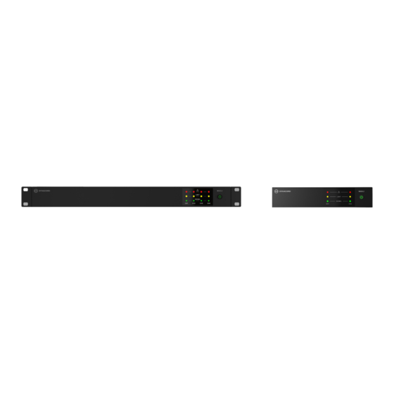
V Series Installation | en Installation – Indicators, controls and settings, page 25 – Connections, page 31 Indicators, controls and settings Front view A B C Indicator description Color Device/channel fault (CH1-4) LIMIT Over driven channel (CH1-4) Yellow SIGNAL Input signal present (CH1-4) - Page 26 | Installation V Series Rear view Description AC mains input socket Fault relay (FLT RDY) contacts and REMOTE ON control input socket AMP MODE (CH1/CH2, CH3/CH4) and DUAL-PARALLEL DIP‑switches FILTER (CH1/CH2, CH3/CH4), APD switches (IN1 to ALL DIP‑switches in V600:4)
-
Page 27: Set The Output Mode (Amp Mode)
V Series Installation | en 5.1.1 Set the output mode (AMP MODE) AMP MODE FILTER AMP MODE FILTER CH 1 CH 2 CH 1 CH 2 IN1 to ALL 100 V HP 100 HP 100 100 V 70 V HP 150... -
Page 28: Set The Input Routing (Dual / Parallel / In1 To All)
| Installation V Series 5.1.2 Set the input routing (DUAL / PARALLEL / IN1 to ALL) DUAL and PARALLEL modes are selected for channels 1‑2 and separately for channels 3‑4, using the DIP switch in the Up position for “DUAL” mode or the Down position for “PARALLEL”... -
Page 29: Set The Loudspeaker Parameters (Filter)
V Series Installation | en 5.1.3 Set the loudspeaker parameters (FILTER) The amplifier’s FILTER settings enable the output audio to be optimized to suit particular types of speakers (e.g. subwoofers) or particular environments, allowing some optimization for voice/speech by reducing the low frequency feedback. -
Page 30: Set The Energy Safe Option (Apd)
| Installation V Series 5.1.4 Set the energy safe option (APD) The APD (Auto Power Down) automatically places the amplifier into a low power standby mode after a period of inactivity when signal, such as a music source, is not present for an extended period. -
Page 31: Connections
V Series Installation | en Connections – Audio inputs, page 31 – Line input RJ45, page 33 – Power outputs, page 34 – Ready/Fault relay, page 35 – Remote on, page 36 – Mains power, page 36 5.2.1 Audio inputs Audio input connectors are either Euroblock type for 2‑channels per connector, or... - Page 32 | Installation V Series Balanced input connection Unbalanced input connection Cold Shield Jumper from cold to shield – The pin out is labeled on the rear of the amplifier. Refer to – Indicators, controls and settings, page 25 2024.01 | V03 | F.01U.402.248...
-
Page 33: Line Input Rj45
V Series Installation | en 5.2.2 Line input RJ45 The line input RJ45 connection can be used for an input of four (V600:4) resp. two (V600:2) audio channels via a single cable, or as audio output/through when the Euroblock inputs are in use. -
Page 34: Power Outputs
| Installation V Series 5.2.3 Power outputs The output connectors are 2 Euroblock type for 2‑channels per connector. This allows an easy pre‑wiring of the cables outside the rack and a fast - one connection for multiple channels at once, without the danger of wiring errors. -
Page 35: Ready/Fault Relay
V Series Installation | en 5.2.4 Ready/Fault relay The Ready/Fault relay is a potential free relay toggle for READY or FAULT indication. This allows the amplifier to notify an external device or indicator that the amplifier status is either “RDY” (all is ok) or “FLT” (fault) and may not be functioning correctly. The next table explains the relay setting for the different operation and error modes. -
Page 36: Remote On
| Installation V Series 5.2.5 Remote on REMOTE ON provides a simple way to remotely power-on/off the power amplifier. REMOTE ON overrides front panel power button when activated. This can be used by an external device or a simple switch that can be located away from the amplifier for convenience. -
Page 37: Operation After Installation
V Series Operation after installation | en Operation after installation Power on The device can be activated by pushing the power button on the front panel. Speaker system switch‑on is delayed by approximately three seconds via output relays, effectively suppressing any possible power‑on noise, which otherwise might be heard through the loudspeakers. -
Page 38: Troubleshooting
| Troubleshooting V Series Troubleshooting Problem Possible cause Solution Amplifier does not turn on Power (plug) disconnected Ensure power cord is and power LED is not or the power source is giving securely connected to device illuminated. insufficient power to the and check the power from device. - Page 39 V Series Troubleshooting | en Problem Possible cause Solution used. See Set the loudspeaker parameters (FILTER), page 29. Weak sound output, but with Incorrectly wired input Ensure that the input cables no fault indications. connectors. are correctly match to the polarity of the source (i.e.
- Page 40 | Troubleshooting V Series Problem Possible cause Solution Output power is reducing, Amplifier is under extreme Consider changing the and LIMIT LED is thermal conditions, well location of the amplifier and illuminating. beyond operating check that there is sufficient specifications of 45 ℃.
-
Page 41: Maintenance
V Series Maintenance | en Maintenance This product has been designed to operate without problems for a long period of time, with a minimum of maintenance. In order to guarantee trouble-free operation periodically: – Clean all units with a damp, lint‑free cloth; never use water or chemicals. -
Page 42: Technical Data
| Technical data V Series Technical data V600:4 Electrical Output power 4 Ω 8 Ω 70 V 100 V Rated output power 4 x 150 W Maximum output power per 500 W 600 W 500 W 600 W channel (power sharing) minimum impedance Total rated output power... - Page 43 V Series Technical data | en Connectivity Analog audio input Type 2 x 6‑pin Euroblock, 3.81 mm, male, parallel 1x RJ45 (AES72-1E) Maximum input level (LEVEL 0 dB) +18 dBu Input impedance, active balanced 20 kΩ Mains Input IEC C14 Loudspeaker output 2 x 4-pin Euroblock, 5.08 mm,...
- Page 44 | Technical data V Series Environmental Climatic conditions Cooling concept Convection cooling in tabletop application and rack application with spacing between units. Forced cooling (side to rear) in rack application without spacing between units and in extreme thermal conditions.
- Page 45 V Series Technical data | en V600:2 Electrical Output power 4 Ω 8 Ω 70 V 100 V Rated output power 2 x 300 W Maximum output power per 500 W 600 W 500 W 600 W channel (power sharing) minimum impedance Total rated output power 600 W Number of channels Output voltage rated output 34.6 V...
- Page 46 | Technical data V Series Connectivity Type 6‑pin Euroblock, 3.81 mm, male, parallel 1x RJ45 Maximum input level (LEVEL 0 dB) +18 dBu Input impedance, active balanced 20 kΩ Mains input IEC C14 Loudspeaker output 4-pin Euroblock, 5.08 mm, female Control port Type 5‑pin Euroblock, 3.81 mm, male...
- Page 47 V Series Technical data | en Climatic conditions cooling (side to rear) in rack application without spacing between units and in extreme thermal conditions. Ambient temperature limits -5 °C to +45 °C (+23 °F to +113 °F) Altitude (operating) -500 m to 5000 m (-1614 ft to 16404 ft)
-
Page 48: V600:4 Block Diagram
| V600:4 Block diagram V Series V600:4 Block diagram POWER ON LINE IN RJ45 IEC MAINS INLET 2024.01 | V03 | F.01U.402.248 Dynacord Installation manual... -
Page 49: V600:2 Block Diagram
V Series V600:2 Block diagram | en V600:2 Block diagram POWER ON LINE IN RJ45 IEC MAINS INLET Dynacord 2024.01 | V03 | F.01U.402.248 Installation manual... -
Page 50: Support And Academy
| Support and academy V Series Support and academy Support Access our support services at www.boschsecurity.com/xc/en/support/. Bosch Security and Safety Systems offers support in these areas: – Apps & Tools – Building Information Modeling – Warranty – Troubleshooting –... - Page 52 Bosch Security Systems B.V. Torenallee 49 5617 BA Eindhoven Netherlands www.dynacord.com © Bosch Security Systems B.V., 2024 202401051514...
Need help?
Do you have a question about the V Series and is the answer not in the manual?
Questions and answers