Table of Contents
Advertisement
Quick Links
Advertisement
Table of Contents

Subscribe to Our Youtube Channel
Related Manuals for Dynacord V600:4


Summary of Contents for Dynacord V600:4
- Page 1 Power amplifier V600:4 Installation manual...
-
Page 3: Table Of Contents
5.2.2 AMP-LINK 5.2.3 Power outputs 5.2.4 Ready/Fault relay 5.2.5 Remote on 5.2.6 Mains power Operation after installation Power on Input level control Troubleshooting Maintenance Technical data Approvals Block diagram Support and academy Dynacord 2023-01 | V02 | F.01U.402.248 Installation manual... -
Page 4: Important Product Information
Safety Information Read and keep these safety instructions. Follow all instructions and heed all warnings. Download the latest version of the applicable installation manual from www.dynacord.com for installation instructions. Information Refer to the Installation Manual for instructions. Follow all installation instructions and observe the following alert signs: Notice! Containing additional information. -
Page 5: Disposal Instructions
Increase the separation between the equipment and receiver. – Connect the equipment into an outlet on a circuit different from that to which the receiver is connected. – Consult the dealer or an experienced radio/TV technician for help. Dynacord 2023-01 | V02 | F.01U.402.248 Installation manual... -
Page 6: About This Manual
Notice of liability While every effort has been taken to ensure the accuracy of this document, neither Dynacord nor any of its official representatives shall have any liability to any person or entity with respect to any liability, loss or damage caused or alleged to be caused directly or indirectly by the information contained in this document. -
Page 7: Document History
Power amplifier About this manual | en Document history Release date Documentation version Reason 2022.02.01 Release Release date Documentation version Reason 2022.02.01 Release Dynacord 2023-01 | V02 | F.01U.402.248 Installation manual... -
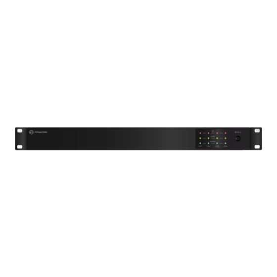
Page 8: Product Introduction
| Product introduction Power amplifier Product introduction The V600:4 is a 600 W power amplifier with powerTANK technology that flexibly delivers the total power over its 4 channels. The amplifier is ideally suited to background music and clear voice announcement applications such as: –... - Page 9 Equipped with a PFC power supply and protection features usually reserved for the professional power amplifiers, means that the amplifier resists complete shutdown situations and will always perform at its best under all conditions. Dynacord 2023-01 | V02 | F.01U.402.248 Installation manual...
-
Page 10: Functional Diagram
Internal and external device functions Signal input AMP‑LINK input Mains input Loudspeaker output REMOTE ON Input RDY/FLT Output Level control Input routing Signal processing (filter, limiter) Amplifier Power supply Controller Failure relay 2023-01 | V02 | F.01U.402.248 Dynacord Installation manual... -
Page 11: General Installation Procedures
The products should be unpacked and handled with care. If an item appears to be damaged, notify the shipper immediately. If any items are missing, notify your Dynacord representative. The original packaging is the safest container in which to transport products and can also be used to return products for service, if necessary. -
Page 12: Dimensions
This power amplifier has been designed for installation in a conventional 19”‑equipment rack. Attach the power amp with its frontal rack mount ears using four screws and washers as shown in the illustration. 2023-01 | V02 | F.01U.402.248 Dynacord Installation manual... - Page 13 When installing the power amp in a case or rack system, attention should be paid to these details to provide sufficient ventilation. Dynacord 2023-01 | V02 | F.01U.402.248 Installation manual...
-
Page 14: Fan Cooling
LEDs on the front panel and the Fault relay. However, even in such a condition the amplifier will operate without switch‑off or reduction if supervised and monitored levels are within the range of silent running parameters. 2023-01 | V02 | F.01U.402.248 Dynacord Installation manual... -
Page 15: Mains Operation And Resulting Temperature
The tables are meant as auxiliary means for calculating temperatures inside of a rack-shelf system/cabinet and the ventilation efforts necessary. The column P lists the leakage power in relation to different operational states. The column BTU/hr lists the dispensed heat amount per hour. V600:4 BTU/hr mains mains mains... -
Page 16: Installation
AMP MODE (CH1/CH2, CH3/CH4) and DUAL-PARALLEL DIP‑switches SPEAKER EQ (CH1/CH2, CH3/CH4), APD and IN1 to ALL DIP‑switches LEVEL control (CH1-4) Line level audio inputs socket (CH1/CH2, CH3/CH4) AMP‑LINK “input” RJ45 socket Loudspeaker OUTPUTS socket (CH1/CH2, CH3/CH4) 2023-01 | V02 | F.01U.402.248 Dynacord Installation manual... -
Page 17: Set The Output Mode (Amp Mode)
This mode usually used if multiple speakers with medium or low‑power rating are driven in low impedance mode (LZ). Refer to – Indicators, controls and settings, page 16 Dynacord 2023-01 | V02 | F.01U.402.248 Installation manual... -
Page 18: Set The Input Routing (Dual / Parallel / In1 To All)
ON or OFF using the IN1 to ALL DIP switch at the rear of the device. Level control CH1 affects the volume of all 4 output channels at the same time. Refer to – Indicators, controls and settings, page 16 2023-01 | V02 | F.01U.402.248 Dynacord Installation manual... -
Page 19: Set The Loudspeaker Parameters (Speaker Eq)
FLAT is designed for full range operation and contains a 30 Hz 24 dB/Oct high‑pass filter for both 4 Ω and 8 Ω operation or the 50 Hz 24 dB/Oct high pass filter when used in 70/100 V operation. Refer to – Indicators, controls and settings, page 16 Dynacord 2023-01 | V02 | F.01U.402.248 Installation manual... -
Page 20: Set The Energy Safe Option (Apd)
2023-01 | V02 | F.01U.402.248 Dynacord Installation manual... -
Page 21: Connections
Due to their immunity against external interference sources, such as dimmers, mains connections, HF-control lines, etc., using balanced cabling and connections is always preferable. Notice! Euroblock input connectors must be inverted when inserting the connector to the device (screws downwards). Dynacord 2023-01 | V02 | F.01U.402.248 Installation manual... - Page 22 Balanced input connection Unbalanced input connection Cold Shield Jumper from cold to shield – The pin out is labeled on the rear of the amplifier. Refer to – Indicators, controls and settings, page 16 2023-01 | V02 | F.01U.402.248 Dynacord Installation manual...
-
Page 23: Amp-Link
Do not connect AMP‑LINK with Ethernet, CAN bus, Call station, or even PoE powered ports! Noise can occur which may damage speakers or the amplifier. Refer to – Indicators, controls and settings, page 16 Dynacord 2023-01 | V02 | F.01U.402.248 Installation manual... -
Page 24: Power Outputs
CH 3 CH 4 CHANNEL 3 CHANNEL 4 CHANNEL 1 CHANNEL 2 HiZ 70 V / 100 V application (Example channel 1) OUTPUTS CH 1 CH 2 Refer to – Indicators, controls and settings, page 16 2023-01 | V02 | F.01U.402.248 Dynacord Installation manual... -
Page 25: Ready/Fault Relay
Internal error, e.g. fan blocked *) RDY/FLT: Indicates the closed contact. Figure A shows the FLT (fault) condition, figure B shows the RDY (all is ok) condition. Refer to – Indicators, controls and settings, page 16 Dynacord 2023-01 | V02 | F.01U.402.248 Installation manual... -
Page 26: Remote On
The front power button doesn't disconnect the device from mains. The only way to switch‑off mains entirely is to remove the power plug. Refer to – Technical data, page 31 – Indicators, controls and settings, page 16 2023-01 | V02 | F.01U.402.248 Dynacord Installation manual... -
Page 27: Operation After Installation
The level control of the unused input is ineffective. If however independent level control is desired, the DUAL routing should be used instead and the inputs wired as parallel. Refer to – Indicators, controls and settings, page 16 Dynacord 2023-01 | V02 | F.01U.402.248 Installation manual... -
Page 28: Troubleshooting
Adjust the speaker settings lacks low frequencies. activated (e.g. LP used with a on the rear of the device and full range speaker). ensure that the settings match they types of speakers used. 2023-01 | V02 | F.01U.402.248 Dynacord Installation manual... - Page 29 Amplifier is under extreme Consider changing the and LIMIT LED is illuminating. thermal conditions, well location of the amplifier and beyond operating check that there is sufficient specifications of 45 ℃. airflow around the amplifier. Dynacord 2023-01 | V02 | F.01U.402.248 Installation manual...
-
Page 30: Maintenance
Vacuum the air vents to ensure good ventilation. – Check all cable connections for corrosion and the screw terminals to make sure that they have not become loosened. – Check the ground (PE) connection of the system components. 2023-01 | V02 | F.01U.402.248 Dynacord Installation manual... -
Page 31: Technical Data
> 101 dB > 103 dB (A‑weighted, ref. to rated output power, LEVEL 0 dB) Output Noise < -68 dBu < -67 dBu < -62 dBu < -61 dBu (A-weighted, LEVEL 0 dB) Dynacord 2023-01 | V02 | F.01U.402.248 Installation manual... - Page 32 Protections Audio limiters, high temperature, DC, HF, short circuit, back‑EMF, peak current limiters, inrush current limiters, mains over/under voltage protection Front status LEDs Signal, limit, fault LEDs per channel; power LED 2023-01 | V02 | F.01U.402.248 Dynacord Installation manual...
- Page 33 44.2 x 483 x 269.5 mm (1.74 x 19.2 x 10.6 in) Weight 3.6 kg (7.9 lb) ) Test signal for max. output power according IHF‑A‑202 (Dynamic-Headroom, burst 1 kHz / 20 ms on / 480 ms off / low level -20 dB) ) Selectable via Speaker EQ. Dynacord 2023-01 | V02 | F.01U.402.248 Installation manual...
-
Page 34: Approvals
| Approvals Power amplifier Approvals Regulatory areas Safety EN/IEC/CSA/UL 62368‑1 Immunity EN 55035, EN 61000‑4‑11 Emissions EN 55032, EN 61000‑3‑2, EN 61000‑3‑3, ICES‑003, e‑CFR Title 47 Chapter I Subchapter A Part 15 Subpart B Environment EN/IEC 63000 2023-01 | V02 | F.01U.402.248 Dynacord Installation manual... -
Page 35: Block Diagram
Power amplifier Block diagram | en Block diagram Dynacord 2023-01 | V02 | F.01U.402.248 Installation manual... -
Page 36: Support And Academy
Warranty – Troubleshooting – Repair & Exchange – Product Security Bosch Building Technologies Academy Visit the Bosch Building Technologies Academy website and have access to training courses, video tutorials and documents: www.boschsecurity.com/xc/en/support/training/ 2023-01 | V02 | F.01U.402.248 Dynacord Installation manual... - Page 37 Power amplifier Support and academy | Dynacord 2023-01 | V02 | F.01U.402.248 Installation manual...
- Page 38 | Support and academy Power amplifier 2023-01 | V02 | F.01U.402.248 Dynacord Installation manual...
- Page 40 Bosch Security Systems B.V. Torenallee 49 5617 BA Eindhoven Netherlands www.boschsecurity.com © Bosch Security Systems B.V., 2023 202303171236...
Need help?
Do you have a question about the V600:4 and is the answer not in the manual?
Questions and answers