Table of Contents
Advertisement
Quick Links
Advertisement
Table of Contents

Related Manuals for Eliminator Lighting IKON PROFILE PLUS


Summary of Contents for Eliminator Lighting IKON PROFILE PLUS
- Page 1 IKON PROFILE PLUS User Manual...
- Page 2 All non-Eliminator brands and product names are trademarks or registered trademarks of their respective companies. Eliminator Lighting and all affiliated companies hereby disclaim any and all liabilities for property, equipment, building, and electrical damages, injuries to any persons, and direct or indirect economic...
-
Page 3: Table Of Contents
C O N T E N T S General Information Limited Warranty (USA Only) Warranty Registration | Features Safety Guidelines Overview Installation Guidelines System Menu Operating Instructions Primary Secondary Configuration Remote Operation DMX Setup DMX Traits Gobo Replacement | Adding a Color Gel Photometric Chart | Gobos | Fuse Replacement Power Linking | Trouble Shooting | Cleaning Dimensional Drawings... -
Page 4: General Information
G E N E R A L I N F O R M AT I O N INTRODUCTION This device is a 40W LED GOBO Projector that includes with 1 glass GOBO and 4 metal GOBOs. Users can also manually control the beam angle, focus, and framing shutters. Compatible with the UC IR wireless remote. -
Page 5: Limited Warranty (Usa Only)
ADJ Products, LLC Service Department at 800-322-6337. Send the product only to the Eliminator Lighting factory. All shipping charges must be pre-paid. If the requested repairs or service (including parts replacement) are within the terms of this warranty, Eliminator Lighting will pay return shipping charges only to a designated point within the United States. -
Page 6: Warranty Registration | Features
WA R R A N T Y R E G I S T R AT I O N This device carries a 2 year limited warranty. Please fill out the enclosed warranty card to validate your purchase. All returned service items, whether under warranty or not, must be freight pre-paid and accompanied by a return authorization (R.A.) number. -
Page 7: Safety Guidelines
S A F E T Y G U I D E L I N E S Safety Issue: This unit may blow the fuse if the maximum current rating of the fuse is reached or exceeded. Please see the section of this manual for Fuse Replacement for detailed directions regard- ing replacement of the fuse. -
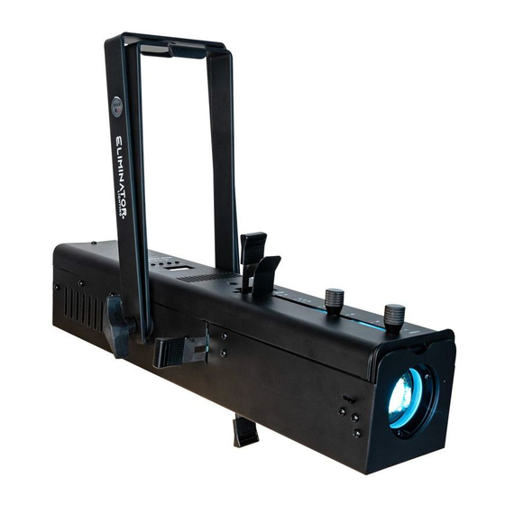
Page 8: Overview
O V E R V I E W Frame Beam Spring Angle and Focus Knobs Framing Blades Indicator Display Screen Bracket Adjustment Bracket Power Knob Adjustment Knob Down Button Mode Button Fuse Power Button Setup Button Mounting Safety Bracket Cable Loop... -
Page 9: Installation Guidelines
I N S TA L L AT I O N G U I D E L I N E S ELECTRICAL CONNECTIONS A qualified electrician should be used for all electrical connections and/or installations. DO NOT INSTALL THE FIXTURE IF YOU ARE NOT QUALIFIED TO DO SO! Fixture MUST be installed following all local, national, and country commercial electrical and construction codes and regulations. - Page 10 I N S TA L L AT I O N G U I D E L I N E S CLAMP INSTALLATION This device features an attachment point for a mounting clamp located on the top of the mounting bracket, as well as a loop for a safety cable located on the rear panel (see illustration below). When mounting the fixture to a truss or any other suspended or overhead installation, align the hole on an appropriately rated clamp (not included) with the hole on the fixture’s bracket, then insert a bolt of the appropriate size and rating through the hole and secure in place with an appropriately rated nut.
- Page 11 I N S TA L L AT I O N G U I D E L I N E S FIXTURE INSTALLATION This device is fully operational in three different mounting positions: hanging upside-down, mounted sideways on trussing, or set on a flat level surface. Be sure this fixture is kept at least 0.2m (7.9in.) away from any flammable materials (decoration etc.).
-
Page 12: System Menu
S Y S T E M M E N U 001 - 512 Set DMX address Address Channel Select DMX channel mode Mode Fixture takes all channels to Black Out zero when DMX signal is lost DMX Settings or interrupted Blackout / Fixture holds most recent Hold... -
Page 13: Operating Instructions
O P E R AT I N G I N S T R U C T I O N S On-Board System Menu. This device features an easy to navigate system menu, with the functions of each command in the system menu detailed below. Please read the next section thoroughly! To access the main menu press the MODE button, then press the UP or DOWN buttons until you reach the function you wish to change. - Page 14 O P E R AT I N G I N S T R U C T I O N S PERSONALITY - Dimmer Mode: 1. Press the MODE button until “Personality” is displayed, then press SETUP. 2. Use the UP and DOWN buttons to scroll to “Dimmer Mode,” then press SETUP. 3.
- Page 15 O P E R AT I N G I N S T R U C T I O N S PERSONALITY - Service: Use this setting to restore the unit to factory settings. 1. Press the MODE button until “Personality” is displayed, then press SETUP. 2.
-
Page 16: Primary Secondary Configuration
P R I M A R Y S E C O N D A R Y C O N F I G U R AT I O N This function allows you to link units together to run in a Primary-Secondary set-up, in which one unit will act as the controlling unit and the others will react to the controlling unit’s built-in programs. -
Page 17: Remote Operation
R E M O T E O P E R AT I O N The UC IR remote (sold seperately) has many different functions and allows you to control your de- vice at a distance of up to 30 ft. STAND BY - This button blacks out the fixture. -
Page 18: Dmx Setup
D M X S E T U P DMX-512: DMX is short for Digital Multiplex. This is a universal protocol that is used as a form of communication between intelligent fixtures and controllers. A DMX controller sends DMX data in- structions from the controller to the fixture. - Page 19 D M X S E T U P Notice: Be sure to follow figures two and three when making your own cables. Do not use the ground lug on the XLR connector. Do not connect the cable’s shield conductor to the ground lug or allow the shield conductor to come in contact with the XLR’s outer casing.
- Page 20 D M X S E T U P All fixtures should be given a DMX starting address when using a DMX controller, so the correct fixture responds to the correct control signal. This digital starting address is the channel number from which the fixture starts to “listen”...
-
Page 21: Dmx Traits
D M X T R A I T S CHANNEL MODE FUNCTION VALUES Strobe 000 - 031 LED Off 032 - 063 LED On 064 - 095 Strobe, slow to fast 096 - 127 LED On 128 - 159 Strobe Pulse, slow to fast 160 - 191 LED On 192 - 223... -
Page 22: Gobo Replacement | Adding A Color Gel
G O B O R E P L A C E M E N T The gobo in this device can be interchanged at any time, allowing the user to customize the system. To replace gobo, follow the steps below: 1. -
Page 23: Photometric Chart | Gobos | Fuse Replacement
P H O T O M E T R I C C H A R T G O B O S F U S E R E P L A C E M E N T Disconnect the unit from its power source. Remove the power cord from the unit, then find the fuse holder located inside the power socket. -
Page 24: Power Linking | Trouble Shooting | Cleaning
P O W E R L I N K I N G This feature allows multiple units to be linked together by way of the power input and output sockets. The maximum number of devices that can be connected in this manner is as follows: 14 units maximum @ 120V. -
Page 25: Dimensional Drawings
D I M E N S I O N A L D R AW I N G S 6.2in (157.73mm) 5.8in (147mm) 3.0in 3.0in (76mm) (76mm) 11.7in (296.61mm) 6.2in (158.23mm) -
Page 26: Specifications
S P E C I F I C AT I O N S • Bright white 40W LED indoor Gobo Projector • High quality optics - Clear powerful output • 3-channel or 4-channel DMX channel modes • 5 Dimmer Curves •... -
Page 27: Fcc Statement
F C C S TAT E M E N T This device complies with Part 15 of the FCC Rules. Operation is subject to the following two conditions: (1) this device may not cause harmful interference, and (2) this device must accept any interference received, including interference that may cause undesired operation.
Need help?
Do you have a question about the IKON PROFILE PLUS and is the answer not in the manual?
Questions and answers