Table of Contents
Advertisement
Quick Links
Advertisement
Table of Contents

Related Manuals for Eliminator Lighting MEGA WASH 24


Summary of Contents for Eliminator Lighting MEGA WASH 24
- Page 1 MEGA WASH 24 User Manual...
- Page 2 All non-Eliminator brands and product names are trademarks or registered trademarks of their respective companies. Eliminator Lighting and all affiliated companies hereby disclaim any and all liabilities for property, equipment, building, and electrical damages, injuries to any persons, and direct or indirect economic...
-
Page 3: Table Of Contents
C O N T E N T S General Information Limited Warranty (USA Only) Safety Guidelines Overview Installation Guidelines Control Panel System Menu Remote Operation Primary-Secondary Setup | Multi Unit Power Linking DMX Setup DMX Traits Cleaning and Maintenance Specifications Dimensional Drawings... -
Page 4: General Information
G E N E R A L I N F O R M AT I O N INTRODUCTION Please read and understand all instructions in this manual carefully and thoroughly before attempting to operate this device. These instructions contain important safety and use information. UNPACKING This device has been thoroughly tested and has been shipped in perfect operating condition. -
Page 5: Limited Warranty (Usa Only)
ADJ Products, LLC Service Department at 800-322-6337. Send the product only to the Eliminator Lighting factory. All shipping charges must be pre-paid. If the requested repairs or service (including parts replacement) are within the terms of this warranty, Eliminator Lighting will pay return shipping charges only to a designated point within the United States. -
Page 6: Safety Guidelines
To guarantee a smooth operation, it is important to follow all instructions and guidelines in this manual. Eliminator Lighting is not responsible for injury and/or damages resulting from the misuse of this fixture due to the disregard of the information printed in this manual. Only qualified and/or certified personnel should perform installation of this fixture and only the original rigging parts included with this fixture should be used for installation. - Page 7 S A F E T Y G U I D E L I N E S • This unit may “pop” the fuse if the maximum allotted load of 5 amps is reached or exceeded. • To reduce the risk of electrical shock or fire, do not expose this unit to rain or moisture. •...
- Page 8 S A F E T Y G U I D E L I N E S RISK GROUP 3 - RISK OF EXPOSURE TO ULTRAVIOLET UV RADIATION! FIXTURE EMITS HIGH INTENSITY WAVELENGTH OF ULTRAVIOLET UV LIGHT FROM THE UV COLOR FILTER. WEAR PROPER EYE AND SKIN PROTECTION.
-
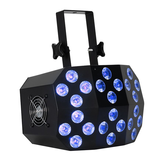
Page 9: Overview
O V E R V I E W Display Screen LED DISPLAY Button Menu MENU DOWN ENTER Button Enter Button Mounting Bracket Down Button Bracket Adjustment Knob Indicator Safety Cable LED DISPLAY Loop SAFTLOOF MENU DOWN ENTER POWER OUT DMX IN DMX OUT POWER IN Power... -
Page 10: Installation Guidelines
I N S TA L L AT I O N G U I D E L I N E S ELECTRICAL CONNECTIONS A qualified electrician should be used for all electrical connections and/or installations. FLAMMABLE MATERIAL WARNING Keep fixture at least 7.9in. (0.2m) away from any flammable materials, decorations, pyrotechnics, etc. - Page 11 I N S TA L L AT I O N G U I D E L I N E S CLAMP INSTALLATION This fixture features a mounting clamp attachment point, which is located on the mounting yoke, as well as a safety cable rigging point, located on the rear face of the unit near the display screen (see the illustration below).
-
Page 12: Control Panel
C O N T R O L PA N E L The device includes an easy to navigate system menu that can be accessed via a set of control buttons located on the back of the device below the digital display. MODE: Press to cycle through main menu options (Auto, Sound, Sec, DMX). -
Page 13: System Menu
S Y S T E M M E N U Addr A001 - A512 Set DMX address 3-channel DMX mode 6-channel DMX mode ChNd 10Ch 10-channel DMX mode 40Ch 40-channel DMX mode Colo CL01 - CL22 Color selection Auto Au01 - Au18 Auto program mode SPed S001 - S100... -
Page 14: Remote Operation
R E M O T E O P E R AT I O N The unit can only be controlled when it has been set to Primary mode. The unit will NOT re- spond to commands when operating in Secondary mode. •... -
Page 15: Primary-Secondary Setup | Multi Unit Power Linking
P R I M A R Y - S E C O N D A R Y S E T U P This function allows you to link units together to run in a Primary-Secondary set-up, in which one unit will act as the controlling unit and the others will react to the controlling unit’s built-in programs. -
Page 16: Dmx Setup
D M X S E T U P DMX-512: DMX is short for Digital Multiplex. This is a universal protocol used as a form of communication between intelligent fixtures and controllers. A DMX controller sends DMX data instructions from the controller to the fixture. - Page 17 D M X S E T U P Special Note: Line Termination. When longer runs of cable are used, you may need to use a terminator on the last unit to avoid erratic behavior. A terminator is a 110-120 ohm 1/4 watt resistor which is connected between pins 2 and 3 of a male XLR connector (DATA + and DATA -).
- Page 18 D M X S E T U P DMX ADDRESSING All fixtures should be given a DMX starting address when operating with a DMX controller, in order to ensure that the correct fixture responds to the correct control signal. This digital starting address is the channel number from which the fixture starts to “listen”...
-
Page 19: Dmx Traits
D M X T R A I T S CHANNEL DMX VALUES FUNCTION 10CH 40CH Red Color, 0% to 100% 0 - 255 Green Color, 0% to 100% 0 - 255 Blue Color, 0% to 100% 0 - 255 White Color, 0% to 100% 0 - 255 Amber Color, 0% to 100% 0 - 255... - Page 20 D M X T R A I T S CHANNEL DMX VALUES FUNCTION 10CH 40CH Auto Mode / Sound Control Mode (continued) 218 - 225 Sound Control Mode 9 226 - 233 Sound Control Mode 10 234 - 241 Sound Control Mode 11 242 - 255 Sound Control Mode 1 - 11 Cycling Auto Mode Speed, slow to fast...
- Page 21 D M X T R A I T S CHANNEL DMX VALUES FUNCTION 10CH 40CH Amber Zone 5, 0% to 100% 0 - 255 UV Zone 5, 0% to 100% 0 - 255 Red Zone 6, 0% to 100% 0 - 255 Green Zone 6, 0% to 100% 0 - 255 Blue Zone 6, 0% to 100%...
-
Page 22: Cleaning And Maintenance
Regular inspections are recommended to ensure proper function and extended life. There are no user serviceable parts inside these devices; please refer all other service issues to Eliminator Lighting. Should you need any spare parts, please order genuine parts from Eliminator Lighting. -
Page 23: Specifications
S P E C I F I C AT I O N S • Input voltage :100V-250V/50-60 HZ • Power supply: 250W • Fuse rating: F5A / 250V • Source: 24 x 6-in-1 10W RGBWA+UV LED lamps • Control: DMX / Sound controller / Auto mode/ Primary-Secondary Mode •... -
Page 24: Dimensional Drawings
D I M E N S I O N A L D R AW I N G S 12.2in (310mm) 8.9in (226mm) - Page 25 This page intentionally left blank.
Need help?
Do you have a question about the MEGA WASH 24 and is the answer not in the manual?
Questions and answers