Table of Contents
Advertisement
Quick Links
Advertisement
Table of Contents

Related Manuals for Eliminator Lighting STRYKER MAX


Summary of Contents for Eliminator Lighting STRYKER MAX
- Page 1 STRYKER MAX User Manual...
- Page 2 All non-Eliminator brands and product names are trademarks or registered trademarks of their respective companies. Eliminator Lighting and all affiliated companies hereby disclaim any and all liabilities for property, equipment, building, and electrical damages, injuries to any persons, and direct or indirect economic...
-
Page 3: Table Of Contents
C O N T E N T S Introduction Limited Warranty (USA Only) Warranty Registration | Features Safety Guidelines Overview Installation Remote Device Management (RDM) Control Panel System Menu Target Mode DMX Setup DMX Traits Primary-Secondary Mode | Multi Unit Power Linking Fuse Replacement | Cleaning Specifications Dimensional Drawings... -
Page 4: Introduction
I N T R O D U C T I O N UNPACKING Thank you for purchasing the Stryker Max by Eliminator Lighting. Every unit has been thoroughly tested and has been shipped in perfect operating condition. Carefully check the shipping carton for damage that may have occurred during shipping. -
Page 5: Limited Warranty (Usa Only)
ADJ Products, LLC Service Department at 800-322-6337. Send the product only to the Eliminator Lighting factory. All shipping charges must be pre-paid. If the requested repairs or service (including parts replacement) are within the terms of this warranty, Eliminator Lighting will pay return shipping charges only to a designated point within the United States. -
Page 6: Warranty Registration | Features
WA R R A N T Y R E G I S T R AT I O N This device carries a 2 year limited warranty. Please fill out the enclosed warranty card to validate your purchase. All returned service items, whether under warranty or not, must be freight pre-paid and accompanied by a return authorization (R.A.) number. -
Page 7: Safety Guidelines
S A F E T Y G U I D E L I N E S • To reduce the risk of electrical shock or fire, do not expose this unit to rain or moisture • Do not spill water or other liquids into or on to your unit. •... -
Page 8: Overview
O V E R V I E W Display Menu Screen Button Button Enter Down Button Button Omega Safety Bracket Cable Mount Attachment Omega Fuse Bracket T4AL Mount 250V Power Power... -
Page 9: Installation
I N S TA L L AT I O N DO NOT INSTALL THE FIXTURE IF YOU ARE NOT QUALIFIED TO DO SO! Fixture MUST be installed following all local, national, and country commercial electrical and construc- tion codes and regulations. When installing the unit, the trussing or area of installation must be able to hold 10 times the weight of the unit and any attached accessories without any deformation. - Page 10 I N S TA L L AT I O N CLAMP MOUNTING This fixture features mounting holes on the underside of the base for the installation of an Omega bracket. To truss mount this unit, attach a mounting clamp to an Omega bracket using an appropri- ately sized nut and bolt.
- Page 11 I N S TA L L AT I O N The unit is fully operational in three different mounting positions: hanging upside-down from the ceil- ing or trussing, sideways on trussing, or set on a flat level surface. Be sure this fixture is kept at least 12m (40ft) away from any flammable materials (decorations, etc).
- Page 12 LEDs. This issue is not specific only to Eliminator lighting fixtures, but rather it is a common issue with lighting fixtures from all manufacturers. Although there is no true way to fully prevent this issue from happen- ing, the guidelines below can reduce the risk of potential damage.
-
Page 13: Remote Device Management (Rdm)
R E M O T E D E V I C E M A N A G E M E N T ( R D M ) NOTE: In order for RDM to work properly, RDM enabled equipment must be used throughout the entire system, including DMX data splitters and wireless systems. -
Page 14: Control Panel
C O N T R O L PA N E L This fixture features a display screen with a 4-button control pad, which can be used to easily adjust any device settings. Pressing the MENU button will cycle through the various Main Menu options. When the desired Main Menu option is displayed on the screen, press the ENTER button to enter the sub-menu, then use the UP and DOWN buttons to scroll through sub-menu options. -
Page 15: System Menu
S Y S T E M M E N U 001 - 512 Address Set DMX address 20 Ch Select DMX channel Mode mode 26 Ch Unit holds last settings received Hold when DMX signal is SETTINGS lost or interrupted No DMX Unit defaults to sound mode when... - Page 16 S Y S T E M M E N U Internal Program 1 Internal Program 2 Internal Program 3 Internal Program 4 Select target mode Program program Internal Program 5 RUN MODE Internal Program 6 Internal Program 7 Internal Program 8 Set program speed.
-
Page 17: Target Mode
TA R G E T M O D E Target modes restrict the pan and tilt movement of the fixture to a certain pre-defined range. To set the unit to operate in target mode, first navigate to Personality > Target Mode in the system menu, then select “On”. -
Page 18: Dmx Setup
D M X S E T U P DMX-512: DMX is short for Digital Multiplex. This is a universal protocol used as a form of communication between intelligent fixtures and controllers. A DMX controller sends DMX data instructions from the controller to the fixture. - Page 19 D M X S E T U P Notice: Be sure to the figures below when making your own cables. Do not use the ground lug on the XLR connector. Do not connect the cable’s shield conductor to the ground lug or allow the shield conductor to come in contact with the XLR’s outer casing.
- Page 20 D M X S E T U P DMX Addressing: All fixtures should be given a DMX starting address when using a DMX controller, in order to ensure that the correct fixture responds to the correct control signal. This digital starting address is the channel number from which the fixture starts to “listen”...
-
Page 21: Dmx Traits
D M X T R A I T S CHANNEL FUNCTION VALUES 20Ch 26Ch 000 - 255 Pan, 8-bit, 0° - 540° 000 - 255 Pan Fine, 16-bit 000 - 255 Tilt, 8-bit, 0° - 190° 000 - 255 Tilt Fine, 16-bit 000 - 255 Red 000 - 255 Green 000 - 255 Blue... - Page 22 D M X T R A I T S CHANNEL FUNCTION VALUES 20Ch 26Ch Glory Effect (continued) 116 - 135 Glory 6pcs LED-4 modules effect 136 - 155 Glory 4 modules effect 156 - 175 Glory loop fill effect 176 - 195 RGB 3 colors rainbow effect 196 - 215 RGB 3 colors effect 216 - 235 Glory rainbow effect 236 - 255 Glory segment effect...
-
Page 23: Primary-Secondary Mode | Multi Unit Power Linking
P R I M A R Y- S E C O N D A R Y M O D E This function will allows you to link units together to run in a Primary-Secondary set-up, in which one unit will act as the controlling unit, and the others will react to the controlling unit’s built-in programs. Any unit can act as a Primary or a Secondary, but only one unit in a given system can be pro- grammed to act as the Primary. -
Page 24: Fuse Replacement | Cleaning
F U S E R E P L A C E M E N T Disconnect the unit from its power source, and remove the power cord from the unit. The fuse is located on the underside of the unit, as shown in the illustration below. Remove the bad fuse and replace with a new one. -
Page 25: Specifications
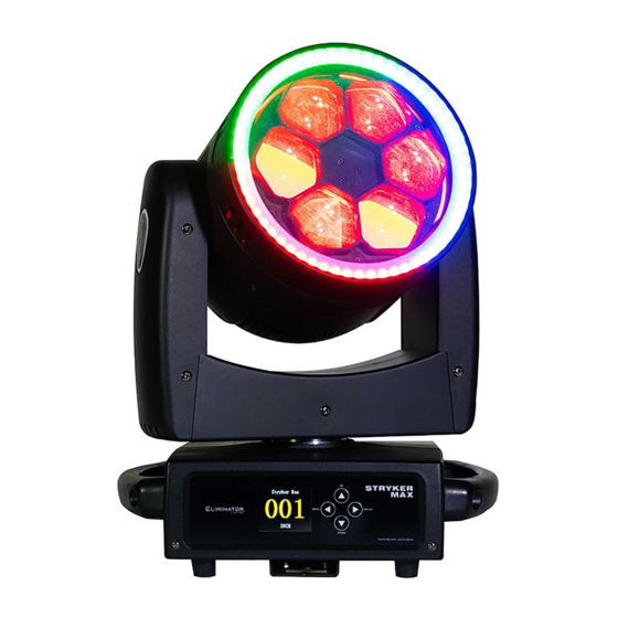
S P E C I F I C AT I O N S Light Source: • 6 x 40-Watt Quad (RGBW) LEDs • LED Ring: 60 x .5-Watt RGB LEDs Features: • Motorized Zoom: 4 ~ 55-degrees • Create eye candy effects with LED Ring •... -
Page 26: Dimensional Drawings
D I M E N S I O N A L D R AW I N G S 10.4in (265mm) 7.3in (185mm) 7.1in (180mm) 11.5in (292mm) 8.2in (208mm) -
Page 27: Fcc Statement
F C C S TAT E M E N T This device complies with Part 15 of the FCC Rules. Operation is subject to the following two conditions: (1) this device may not cause harmful interference, and (2) this device must accept any interference received, including interference that may cause undesired operation.
Need help?
Do you have a question about the STRYKER MAX and is the answer not in the manual?
Questions and answers