Table of Contents
Advertisement
Quick Links
Advertisement
Table of Contents

Related Manuals for Eliminator Lighting MEGA FLAT HEX PAK


Summary of Contents for Eliminator Lighting MEGA FLAT HEX PAK
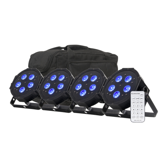
- Page 1 MEGA FLAT HEX PAK User Instructions 07/17/2023...
- Page 2 ©2023 ADJ Products, LLC all rights reserved. Information, specifications, diagrams, images, and instructions herein are subject to change without notice. ADJ Products, LLC logo and identifying product names and numbers herein are trademarks of ADJ Products, LLC. Copyright protection claimed includes all forms and matters of copyrightable materials and information now allowed by statutory or judicial law or hereinafter granted.
-
Page 3: Table Of Contents
C O N T E N T S General Information Limited Warranty (USA Only) Safety Guidelines Overview UC IR Remote | Controls Wireless Setup System Menu Dimmer Curve Modes Primary-Secondary Configuration | Multiple Unit Power Linking DMX Setup DMX Addressing DMX Traits Color Macros Fuse Replacement | Trouble Shooting | Cleaning... -
Page 4: General Information
G E N E R A L I N F O R M AT I O N INTRODUCTION Please read and understand the instructions in this manual carefully and thoroughly before attempting to operate this device. These instructions contain important safety and use information. This product is intended for use by professionally trained personnel only, and is not suitable for private use. -
Page 5: Limited Warranty (Usa Only)
L I M I T E D WA R R A N T Y ( U S A O N LY ) A. Eliminator Lighting, an ADJ Products, LLC brand, hereby warrants, to the original purchaser, ADJ Products, LLC products to be free of manufacturing defects in material and workmanship for a prescribed period from the date of purchase (see specific warranty period on reverse). -
Page 6: Safety Guidelines
S A F E T Y G U I D E L I N E S • RISK GROUP 3 - RISK OF EXPOSURE TO ULTRAVIOLET (UV) RADIATION! • FIXTURE EMITS HIGH INTENSITY WAVELENGTH ULTRAVIOLET LIGHT. • WEAR PROPER EYE AND SKIN PROTECTION. •... -
Page 7: Overview
O V E R V I E W POWER OUT 3pin DMX Out Thumb Knob Clamp Mounting Hole Rubber Footing POWER IN: 100V-240V 3pin DMX IN Mounting Yoke/Stand 50HZ/60HZ... -
Page 8: Uc Ir Remote | Controls
U C I R R E M O T E C O N T R O L The UC IR (sold separately) infrared remote gives you control of various functions (See below). To control the fixture you must aim the remote at the front of the fixture and be no more than 30 feet away. To use the ELIMINATOR UC IR you must first activate the fixtures infrared sensor, to activate the sensor please see the instructions on page 23. -
Page 9: Wireless Setup
W I R E L E S S S E T U P There are many factors that can affect and/or interrupt a wireless signal, including walls, glass, metal, objects, and people. Therefore, the following guidelines are recommended in order to maximize the chances of having a clear path for the wireless signal to reach the device: •... -
Page 10: System Menu
S Y S T E M M E N U This fixture includes an easy to navigate control panel display, from which all necessary settings and adjustments can be made. Press the MODE button to scroll through the main menu options, then press ENTER to select the currently displayed option. - Page 11 S Y S T E M M E N U MODE SET UP UP/DOWN DESCRIPTION Address Set DMX starting address d001 ~ d512 Ch06 Ch07 Channels Select DMX channel mode Ch08 Ch11 Ch12 When DMX signal is lost or interrupted, blAc unit switches all LEDs off DMX Mode...
- Page 12 S Y S T E M M E N U LED Display On/Off: To set the LED display to turn off after 10 seconds of inactivity, press the MODE button until “don” is displayed, then press the UP button to scroll to “doff”. Now the display will disappear after 10s of inactivity.
- Page 13 S Y S T E M M E N U RGBWA + UV Dimmer Mode: 1. Plug the fixture in and press the MODE button until “r.XXX” is displayed. This indicates that the fixture is in Red dimming mode. 2. Press the UP and DOWN buttons to adjust intensity. After you have finished adjusting the intensity, or if you would like to skip to the next color, press the SET UP button.
- Page 14 S Y S T E M M E N U Dimmer Curve Setting: 1. Plug the fixture in and press the MODE button until “d.XXX” is displayed, then press the SET UP button until “dr-X” is displayed. “X” represents a number between 0-4. 2.
-
Page 15: Dimmer Curve Modes
D I M M E R C U R V E C H A R T DIMMER 100% Time (ms) 0 Sec Rise Time Down Time 0 sec Fade Time 1 sec Fade Time Dimming Curve Ramp Effect Rise Time (ms) Down Time (ms) Rise Time (ms) Down Time (ms) Standard (default) Stage 1100... -
Page 16: Primary-Secondary Configuration | Multiple Unit Power Linking
P R I M A R Y - S E C O N D A R Y C O N F I G U R A T I O N These units can be linked together to run in a primary-secondary setup, in which one unit will act as the controlling unit and the others will react to the controlling unit’s built-in programs. -
Page 17: Dmx Setup
D M X S E T U P DMX-512: DMX is short for Digital Multiplex. This is a universal protocol used as a form of communication between intelligent fixtures and controllers. A DMX controller sends DMX data instructions from the controller to the fixture. -
Page 18: Dmx Addressing
DMX ADDRESSING All fixtures should be given a DMX starting address when using a DMX controller, so the correct fixture responds to the correct control signal. This digital starting address is the channel number from which the fixture starts to “listen” to the digital control signal sent out from the DMX controller. The assignment of this starting DMX address is achieved by setting the correct DMX address on the digital control display on the fixture. -
Page 19: Dmx Traits
D M X T R A I T S CHANNEL FUNCTION VALUES 11CH 12CH Red, 0% to 100% 000 - 255 000 - 255 Green, 0% to 100% 000 - 255 Blue, 0% to 100% 000 - 255 White, 0% to 100% Amber, 0% to 100% 000 - 255 UV, 0% to 100%... - Page 20 D M X T R A I T S CHANNEL FUNCTION VALUES 11CH 12CH Color Fade Programs 000 - 015 Color Fade 1 016 - 031 Color Fade 2 032 - 047 Color Fade 3 048 - 063 Color Fade 4 064 - 079 Color Fade 5 080 - 095...
- Page 21 D M X T R A I T S CHANNEL FUNCTION VALUES 11CH 12CH Program Speed / Sound Sensitivity Program Speed, slow to fast 000 - 255 Sound Sensitivity, least to most 000 - 255 sensitive Dimmer Curves 000 - 020 Standard 021 - 040 Stage...
-
Page 22: Color Macros
C O L O R M A C R O S DMX VALUES COLOR MACRO DMX VALUES COLOR MACRO 144-147 G+W+UV 148-151 G+A+UV 8-11 Green 152-155 B+W+A 12-15 Blue 156-159 B+W+UV 16-19 White 160-163 B+A+UV 20-23 Amber 164-167 W+A+UV 24-27 168-171 R+G+B+W 28-31... -
Page 23: Fuse Replacement | Trouble Shooting | Cleaning
F U S E R E P L A C E M E N T Disconnect the unit from its power source and remove the power cord. Find that the fuse holder is located inside the power socket, then insert a flat-head screw driver into the power socket and gently pry out the fuse holder. -
Page 24: Specifications
S P E C I F I C A T I O N S Mega Hex Par Specifications: • Vibrant slim flat black Par with 5 x 6-Watt, 6-IN-1 Hex (RGBWA+UV) LEDs • HEX LEDs allow for a wider pallet of colors like hot pink, lime green and electric blue •... - Page 25 D I M E N S I O N A L D R A W I N G S 8.14”/207mm 6.88”/175mm 8.14”/207mm 3.93”/100mm...
Need help?
Do you have a question about the MEGA FLAT HEX PAK and is the answer not in the manual?
Questions and answers