Table of Contents
Advertisement
Quick Links
Advertisement
Table of Contents

Related Manuals for Eliminator Lighting MBDMX-PLUS


Summary of Contents for Eliminator Lighting MBDMX-PLUS
- Page 1 MBDMX-PLUS User Manual...
- Page 2 All non-Eliminator brands and product names are trademarks or registered trademarks of their respective companies. Eliminator Lighting and all affiliated companies hereby disclaim any and all liabilities for property, equipment, building, and electrical damages, injuries to any persons, and direct or indirect economic...
-
Page 3: Table Of Contents
C O N T E N T S General Information Limited Warranty (USA Only) Warranty Registration | Description | Features Safety Guidelines Maintenance Guidelines DMX Set Up Operating Instructions UC IR Remote Control Mounting Circuit Breaker DMX Traits Dipswitch Settings DMX Address Quick Reference Chart Specifications... -
Page 4: General Information
Caution! There are no user serviceable parts inside this unit. Do not attempt any repairs yourself, as doing so will void your manufacturer’s warranty. In the unlikely event your unit may require service, please contact Eliminator Lighting. PLEASE recycle the shipping carton when ever possible. -
Page 5: Limited Warranty (Usa Only)
ADJ Products, LLC Service Department at 800-322-6337. Send the product only to the Eliminator Lighting factory. All shipping charges must be pre-paid. If the requested repairs or service (including parts replacement) are within the terms of this warranty, Eliminator Lighting will pay return shipping charges only to a designated point within the United States. -
Page 6: Warranty Registration | Description | Features
WA R R A N T Y R E T U R N S All returned service items, whether under warranty or not, must be freight pre-paid and accompanied by a return authorization (R.A.) number. The R.A. number must be clearly written on the outside of the return package. -
Page 7: Safety Guidelines
This device is a sophisticated piece of electronic equipment. To guarantee a smooth operation, it is important to follow all instructions and guidelines in this manual. Eliminator Lighting is not responsible for injury and/or damages resulting from the misuse of this device due to the disregard of the informa- tion printed in this manual. -
Page 8: Maintenance Guidelines
M A I N T E N A N C E G U I D E L I N E S DISCONNECT POWER BEFORE PERFORMING ANY MAINTENANCE! CLEANING Frequent cleaning is recommended to ensure proper function and an extended life. The frequency of cleaning depends on the environment in which the device operates: damp, smoky, or particularly dirty environments can cause greater accumulation of dirt on the fixture’s surface and vents. -
Page 9: Dmx Set Up
D M X S E T U P Power Supply: Always make sure that the voltage of the power source matches the required voltage of the device before plugging in your device. DMX-512: DMX is short for Digital Multiplex. This is a universal protocol used as a form of communi- cation between intelligent fixtures and controllers. - Page 10 D M X S E T U P Notice: Be sure to follow figures two and three when making your own cables. Do not use the ground lug on the XLR connector. Do not connect the cable’s shield conductor to the ground lug or allow the shield conductor to come into contact with the XLR’s outer casing.
-
Page 11: Operating Instructions
O P E R AT I N G I N S T R U C T I O N S Operating Modes: This device features three different operating modes. Always be sure to disconnect the power supply after changing the operating mode in order to allow the unit to reset to the new operating mode. Fail- ure to disconnect the power supply after changing the operating mode may cause the unit to function improperly. - Page 12 O P E R AT I N G I N S T R U C T I O N S Universal DMX Control: This function allows you to use a universal DMX-512 controller to control rotation speed, rotation direction, and the built-in power sockets (usually for pinspots). Operating through a DMX controller allows the freedom to create unique and customized programs tailored to the user’s specific individual needs.
-
Page 13: Uc Ir Remote Control
U C I R R E M O T E C O N T R O L The UC-IR infrared remote gives you control of various functions, as listed below. To control the device, connect the included IR receiver cable to the mini input jack located on the side of the de- vice near the dip switches, and aim the remote at the front of the fixture. -
Page 14: Mounting
M O U N T I N G This device includes a built-in rigging point, and two large holes in the base of the unit for use as safety cable attachment points. The rigging point is located on the top of the unit. This rigging point is secured to the fixture by two large Phillips screws. -
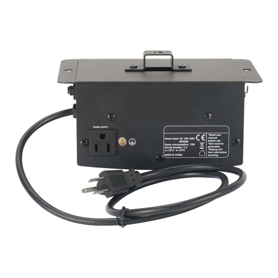
Page 15: Circuit Breaker
C I R C U I T B R E A K E R This unit is equipped with a 3A Circuit Breaker, or GFI (Ground Fault Interrupt). This circuit breaker is designed to close the power circuit in the event of an internal short or power surge. This will reduce the risk of electrical shock or fire and protect the circuitry. -
Page 16: Dmx Traits
D M X T R A I T S The chart below details the DMX traits in depth. The individual trait can only be accessed by using a universal DMX controller. Note: “Lamp” in channel 1 refers to the power socket located on the front of the motor (this socket is intended to be used with lamps that illuminate up the mirror ball). -
Page 17: Dipswitch Settings
D I P S W I T C H S E T T I N G S The chart below details the Primary/Secondary setting for Primary/Secondary configuration. Use this configuration when you will be using two or more fixtures in a Primary/Secondary configuration. Note: The “Primary”... -
Page 18: Dmx Address Quick Reference Chart
D M X A D D R E S S Q U I C K R E F E R E N C E C H A R T This chart lists DMX dip switch settings for DMX address 1 through 511. Follow the instructions below to configure fixture dip siwtches with the desired DMX Address. -
Page 19: Specifications
S P E C I F I C AT I O N S • Heavy Duty DMX Mirror Ball Motor • Includes two 3-prong Edison sockets to power Pinspots • 2 DMX Channels: Channel 1: Turns On/Off Pinspots Channel 2: Adjustable motor speed and direction control of mirror ball; For use with up to a 20- inch mirror ball •...
Need help?
Do you have a question about the MBDMX-PLUS and is the answer not in the manual?
Questions and answers