Table of Contents
Advertisement
Quick Links
Advertisement
Table of Contents

Related Manuals for Eliminator Lighting STRYKER BEAM


Summary of Contents for Eliminator Lighting STRYKER BEAM
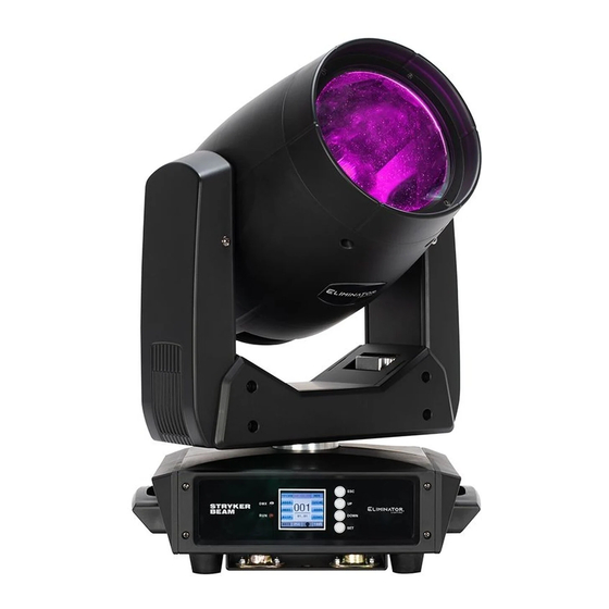
- Page 1 STRYKER BEAM User Manual...
- Page 2 ©2023 Eliminator Lighting all rights reserved. Information, specifications, diagrams, images, and instructions herein are subject to change without notice. Eliminator Lighting logo and identifying prod- uct names and numbers herein are trademarks of ADJ Products, LLC. Copyright protection claimed includes all forms and matters of copyrightable materials and information now allowed by statutory or judicial law or hereinafter granted.
-
Page 3: Table Of Contents
T A B L E O F C O N T E N T S Introduction Limited Warranty (USA Only) | Warranty Registration Features Safety Precautions Overview Installation Color Wheel | Gobos Control Panel System Menu DMX Set Up DMX Traits Primary-Secondary Set Up Maintenance Guidelines Dimensional Drawings... -
Page 4: Introduction
I N T R O D U C T I O N Unpacking: Thank you for purchasing the Stryker Beam. Every device has been thoroughly tested and has been shipped in perfect operating condition. Carefully check the shipping carton for damage that may have occurred during shipping. -
Page 5: Limited Warranty (Usa Only) | Warranty Registration
L I M I T E D W A R R A N T Y ( U S A O N L Y ) 1 Year Limited Warranty: The Eliminator Lighting warranty is valid for 1 year from the date of purchase. Our 1 year limited warranty covers manufacturing defects only. -
Page 6: Features
F E A T U R E S • 1 x 100W LED • Multiple selectable DMX channel modes • Pan and tilt adjustment • 13 colors • 11 static gobos • Effect wheel with bi-directional rotating prisms • Single 6-color chip • Adjustable dimming and strobing • LCD display INCLUDED ITEMS • Power Cable (x1) •... -
Page 7: Safety Precautions
S A F E T Y P R E C A U T I O N S PROTECTION CLASS 1 - FIXTURE MUST BE PROPERLY GROUNDED. THERE ARE NO USER SERVICEABLE PARTS INSIDE THIS UNIT. DO NOT ATTEMPT ANY REPAIRS YOURSELF, AS DOING SO WILL VOID YOUR MANUFACTURER’S WARRANTY. -
Page 8: Overview
O V E R V I E W Button Button Down Button Display Button Screen 3pin Fuse DMX In 3pin 5pin 5pin Power Power DMX Out DMX In DMX Out... -
Page 9: Installation
I N S T A L L A T I O N DO NOT INSTALL THE FIXTURE IF YOU ARE NOT QUALIFIED TO DO SO! Fixture MUST be installed following all local, national, and country commercial electrical and construc- tion codes and regulations. When installing the unit, the trussing or area of installation must be able to hold at least 10 times the weight of the unit and any attached accessories without any deformation. - Page 10 I N S T A L L A T I O N CLAMP MOUNTING This fixture features attachment points for two mounting clamps on the bottom surface of the unit. Additionally, the unit also features a safety cable loop located just below the display screen (see the illustration below).
- Page 11 I N S T A L L A T I O N RIGGING ORIENTATIONS Overhead rigging requires extensive experience, including calculating working load limits, installation material being used, and periodic safety inspection of all installation material and the fixture, among other skills.
- Page 12 LEDs. This issue is not specific only to Eliminator lighting fixtures, but rather it is a common issue with light- ing fixtures from all manufacturers. Although there is no true way to fully prevent this issue from hap- pening, the guidelines below can reduce the risk of potential damage.
-
Page 13: Color Wheel | Gobos
C O L O R W H E E L Open Purple Orange Orange Yellow Light Blue Yellow Green Silver Reseda Yellow Pink Carmine Royal Blue G O B O S Open... -
Page 14: Control Panel
C O N T R O L P A N E L The Stryker Beam features a display screen with a 6-button control pad, which can be used to easily adjust any device settings. Pressing the UP and DOWN buttons to scroll through options on the screen. Press SET to select the option currently highlighted on the screen, and enter into the Sub-Menu to adjust that setting, if appli- cable. -
Page 15: System Menu
S Y S T E M M E N U 001 - 512 Select DMX address Prev ADDR Next 13 CH Select DMX channel Chan mode 19 CH DMX Ctrl DMX control mode Auto Run Auto run mode Sound Ctrl Sound active mode Auto MODE... - Page 16 S Y S T E M M E N U 09. Focus 000 - 255 10. Prism 1 000 - 255 11. Prism 1 R 000 - 255 12. Prism 2 000 - 255 13. Prism 2 R 000 - 255 SCENE 14.
- Page 17 S Y S T E M M E N U Tilt Pan OP Tilt OP 01 Pan 02 Tilt 03 Gobo1 STAT Stepper Info 04 Color1 05 Prism1 06 Prism2 07 Prism Rot1 08 Prism Rot2 09 Focus1 10 Frost 11 MT1 Rainbow mirror motor Error Logging...
-
Page 18: Dmx Set Up
D M X S E T U P DMX-512: DMX is short for Digital Multiplex. This is a universal protocol used as a form of commu- nication between intelligent fixtures and controllers. A DMX controller sends DMX data instructions from the controller to the fixture. DMX data is sent as serial data that travels from fixture to fixture via the DATA “IN”... - Page 19 D M X S E T U P Data Cable (DMX Cable) Requirements (For DMX Operation): This unit can be controlled via DMX-512 protocol. The DMX address is set on the rear panel of the unit. Your unit and your DMX controller require a standard 3-pin or 5-pin XLR connector for data input and data output.
- Page 20 D M X S E T U P DMX ADDRESSING. All fixtures should be given a DMX starting address when using a DMX controller, so the correct fix- ture responds to the correct control signal. This digital starting address is the channel number from which the fixture starts to “listen”...
-
Page 21: Dmx Traits
D M X T R A I T S CHANNEL FUNCTION VALUES 13Ch 19Ch 000 - 255 Pan, 0 - 540 000 - 255 Pan Fine 000 - 255 Tilt, 0 - 225 000 - 255 Tilt Fine Color 000 - 004 White 005 - 009 White + Red 010 - 014 Red 015 - 019 Red + Orange... - Page 22 D M X T R A I T S CHANNEL FUNCTION VALUES 13Ch 19Ch Gobo 000 - 009 Open 010 - 019 Gobo1 020 - 029 Gobo2 030 - 039 Gobo3 040 - 049 Gobo4 050 - 059 Gobo5 060 - 069 Gobo6 070 - 079 Gobo7 080 - 089 Gobo8 090 - 099 Gobo9...
- Page 23 D M X T R A I T S CHANNEL FUNCTION VALUES 13Ch 19Ch Prism 1 000 - 127 Off 128 - 255 On Prism 1 Rotation 000 - 063 Prism Index, 0° - 400° 064 - 126 Clockwise Rotation, fast to slow 127 - 128 Stop 129 - 191 Counter Clockwise Rotation, slow to fast 192 - 255 Bi-directional Rotation, slow to fast...
-
Page 24: Primary-Secondary Set Up
P R I M A R Y - S E C O N D A R Y S E T U P This function allows you to link units together to run in a Primary-Secondary set-up, in which one unit will act as the controlling unit and the others will react to the controlling unit’s built-in programs. -
Page 25: Maintenance Guidelines
M A I N T E N A N C E G U I D E L I N E S DISCONNECT POWER BEFORE PERFORMING ANY MAINTENANCE! CLEANING Frequent cleaning is recommended to ensure proper function, optimized light output, and an extend- ed life. -
Page 26: Dimensional Drawings
D I M E N S I O N A L D R A W I N G S 11.0in (279mm) 11.5in (291mm) 7.9in (200mm) 11.6in (295mm) Drawings not shown to scale. -
Page 27: Specifications
S P E C I F I C A T I O N S Model: Stryker Beam Input Power: AC 100-240V, 50/60 Hz Power Consumption: 150W LED: 1 x 100W LED DMX Channel: 13 / 19 channels Pan Scan: 540° (16bit) electric correction Tilt Scan: 225°...
Need help?
Do you have a question about the STRYKER BEAM and is the answer not in the manual?
Questions and answers