Table of Contents
Advertisement
Quick Links
Advertisement
Table of Contents

Related Manuals for Eliminator Lighting MIN130


Summary of Contents for Eliminator Lighting MIN130
- Page 1 Mini Par Bar Mini Par Bar User Manual SKU#: MIN130 UPC#: 818651029925...
- Page 2 Eliminator Lighting and all affiliated companies hereby disclaim any and all liabilities for property, equipment, building, and electrical damages, injuries to any persons, and direct or indirect economic...
-
Page 3: Table Of Contents
C O N T E N T S General Information Limited Warranty (USA Only) Safety Guidelines Maintenance Guidelines DMX Setup Overview Installation Instructions System Menu DMX Addressing DMX Traits Remote Control Dimensional Drawing Specifications... -
Page 4: General Information
In the unlikely event that your unit may require service, please contact Eliminator Lighting. Eliminator Lighting will not accept any liability for any resulting damages caused by the non-observance of information in this manual or any unauthor- ized modifications to this unit. -
Page 5: Limited Warranty (Usa Only)
This warranty is the only written warranty applicable to Eliminator Lighting, an ADJ Products, LLC brand, and su- persedes all prior warranties and written descriptions of warranty terms and conditions heretofore published. -
Page 6: Safety Guidelines
S A F E T Y G U I D E L I N E S THERE ARE NO USER SERVICEABLE PARTS INSIDE THESE DEVICES. DO NOT ATTEMPT ANY REPAIRS YOURSELF; DOING SO WILL VOID YOUR MANUFAC- TURER’S WARRANTY. DAMAGES RESULTING FROM MODIFICATIONS TO THESE DEVICES AND/OR THE DISREGARD OF SAFETY INSTRUCTIONS AND GUIDE- LINES IN THIS MANUAL VOID THE MANUFACTURER’S WARRANTY AND ARE NOT SUBJECT TO ANY WARRANTY CLAIMS AND/OR REPAIRS. - Page 7 S A F E T Y G U I D E L I N E S This unit may “pop” the fuse if the maximum allotted load of 2 amps is reached. • To reduce the risk of electrical shock or fire, do not expose this device rain or moisture. •...
-
Page 8: Maintenance Guidelines
Regular inspections are recommended to ensure proper function and extended life. There are no user serviceable parts inside these devices; please refer all other service issues to Eliminator Light- ing. Should you need any spare parts, please order genuine parts from Eliminator Lighting. Please refer to the following points during routine inspections: •... - Page 9 M A I N T E N A N C E G U I D E L I N E S FUSE REPLACEMENT The mounting bar features a replaceable fuse housed in a fuse clip below the Power Input on the back side of the device.
-
Page 10: Dmx Setup
D M X S E T U P DMX-512: DMX is short for Digital Multiplex. This is a universal protocol used as a form of commu- nication between intelligent fixtures and controllers. A DMX controller sends DMX data instructions from the controller to the fixture. DMX data is sent as serial data that travels from fixture to fixture via the DATA “IN”... - Page 11 D M X S E T U P Notice: Be sure to follow figures two and three when making your own cables. Do not use the ground lug on the XLR connector. Do not connect the cable’s shield conductor to the ground lug or allow the shield conductor to come into contact with the XLR cable’s outer casing.
-
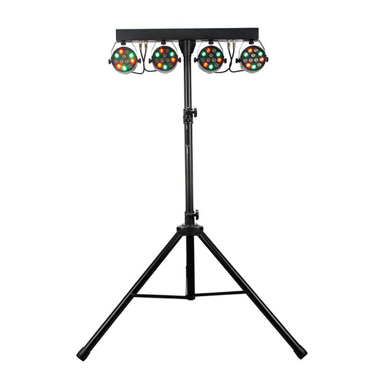
Page 12: Overview
O V E R V I E W MOUNTING BAR AND LIGHTING FIXTURES 1. Fixture Power/Data Cable 2. Fixture Cable Connection Port (x4) 3. Pole Mount Socket and Thumbscrew 4. Fixture Mounting Yoke 5. Fixture Mounting Thumbscrew 6. Bar Power Connector w/ Fuse 7. - Page 13 O V E R V I E W TRIPOD STAND 15. Height Adjustment Knob 16. Leg Adjustment Knob 17. Collapsible Legs (x3)
-
Page 14: Installation Instructions
I N S T A L L A T I O N I N S T R U C T I O N S FLAMMABLE MATERIAL WARNING Keep devices at least 5.0 feet (1.5m) away from flammable materials and/or pyrotech- nics. - Page 15 I N S T A L L A T I O N I N S T R U C T I O N S CLAMP INSTALLATION The mounting bar features two mounting clamp attachment points, with one mounting point located at each end of the top face.
- Page 16 I N S T A L L A T I O N I N S T R U C T I O N S TRIPOD STAND MOUNT The bar features a pole mount socket that allows the device to be mounted securely atop the tripod stand.
-
Page 17: System Menu
S Y S T E M M E N U CONTROL PANEL The device includes an easy to navigate system menu that can be accessed via a set of control but- tons located on the back face of the device below the digital display. MENU: Press to cycle through main menu options. - Page 18 S Y S T E M M E N U MENU FUNCTION DESCRIPTION dxxx d001 - d512 DMX address setting iPxx iP01 - iP64 IP mode setting A1.01 Static color mode, R+G+B+W A1.02 Static color mode, R A1.03 Static color mode, G A1.04 Static color mode, B A1.05...
- Page 19 S Y S T E M M E N U MENU FUNCTION DESCRIPTION A3.12 Fade mode, G+B A3.13 Fade mode, G+W A3.14 Fade mode, B+W A3.15 Fade mode, R+G+W A3.xx (continued) A3.16 Fade mode, R+B+W A3.17 Fade mode, G+B+W A3.18 Fade mode, R+G+B A3.19 Fade mode, R+G+B+W...
- Page 20 S Y S T E M M E N U MENU FUNCTION DESCRIPTION A5.01 Strobe mode, color change A5.02 Strobe mode, GBW on + R strobe A5.03 Strobe mode, RBW on + G strobe A5.04 Strobe mode, RGW on + B strobe A5.05 Strobe mode, BW on + RG strobe A5.06...
-
Page 21: Dmx Addressing
D M X A D D R E S S I N G All fixtures should be given a DMX starting address when operating with a DMX controller, in order to ensure that the correct fixture responds to the correct control signal. This digital starting address is the channel number from which the fixture starts to “listen”... -
Page 22: Dmx Traits
D M X T R A I T S Eliminator Mini Par Bar - DMX Traits Software Version CHANNEL DMX VALUE DESCRIPTION Mode 000 - 010 No function 011 - 050 Macro A1: Macro color 051 - 100 Macro A2: 18 color change 101 - 150 Macro A3: Fade mode 151 - 200... - Page 23 D M X T R A I T S Eliminator Mini Par Bar - DMX Traits Software Version CHANNEL DMX VALUE DESCRIPTION Fade 000 - 039 All color fade 040 - 049 Red color fade 050 - 059 Green color fade 060 - 069 Blue color fade 070 - 079...
- Page 24 D M X T R A I T S Eliminator Mini Par Bar - DMX Traits Software Version CHANNEL DMX VALUE DESCRIPTION Sound Active (continued) 130 - 139 Pink color strobe 140 - 149 Red + white color strobe 150 - 159 Dark green color strobe 160 - 169 Green + white...
- Page 25 D M X T R A I T S Eliminator Mini Par Bar - DMX Traits Software Version CHANNEL DMX VALUE DESCRIPTION Adjustable Speed, slow to fast 000 - 255 Master Dimming, 0% - 100% 000 - 255 Red color, 0% - 100% 000 - 255 Green color, 0% - 100% 000 - 255...
-
Page 26: Remote Control
R E M O T E C O N T R O L BUTTON FUNCTION All Lights On Power Turn Device On/Off Color Jump Change Color Gradual Change Sound Active Mode Strobe Mode Color +/- Color Adjustment Speed +/- Speed Adjustment DMX +/- DMX Channel Select IP +/-... -
Page 27: Dimensional Drawing
D I M E N S I O N A L D R A W I N G LIGHT FIXTURE... - Page 28 D I M E N S I O N A L D R A W I N G TRIPOD STAND NOTE: Bottom illustration depicts tripod legs in fully deployed position.
- Page 29 D I M E N S I O N A L D R A W I N G TRANSPORTATION BAG...
-
Page 30: Specifications
S P E C I F I C A T I O N S • Main Power: AC 120-240V, 50-60Hz • Rated Power Draw: 60W • Fuse: 2A • Control Modes: DMX Control (8-Channel Mode) / Auto / Sound-to-Light / Remote Control •...
Need help?
Do you have a question about the MIN130 and is the answer not in the manual?
Questions and answers