Table of Contents
Advertisement
Quick Links
Advertisement
Table of Contents

Subscribe to Our Youtube Channel
Related Manuals for Eliminator Lighting STRYKER WASH


Summary of Contents for Eliminator Lighting STRYKER WASH
- Page 1 STRYKER WASH User Manual...
- Page 2 ©2023 Eliminator Lighting all rights reserved. Information, specifications, diagrams, images, and instructions herein are subject to change without notice. Eliminator Lighting logo and identifying prod- uct names and numbers herein are trademarks of ADJ Products, LLC. Copyright protection claimed includes all forms and matters of copyrightable materials and information now allowed by statutory or judicial law or hereinafter granted.
-
Page 3: Table Of Contents
T A B L E O F C O N T E N T S Introduction Limited Warranty (USA Only) | Warranty Registration Features Safety Precautions Overview Installation Control Panel System Menu DMX Set Up DMX Traits Primary-Secondary Set Up | Power Linking Maintenance Guidelines Dimensional Drawings Specifications... -
Page 4: Introduction
I N T R O D U C T I O N Unpacking: Thank you for purchasing the Stryker Wash. Every device has been thoroughly tested and has been shipped in perfect operating condition. Carefully check the shipping carton for damage that may have occurred during shipping. -
Page 5: Limited Warranty (Usa Only) | Warranty Registration
L I M I T E D W A R R A N T Y ( U S A O N L Y ) 1 Year Limited Warranty: The Eliminator Lighting warranty is valid for 1 year from the date of purchase. Our 1 year limited warranty covers manufacturing defects only. -
Page 6: Features
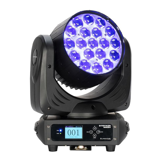
F E A T U R E S • 19 x 12W high power RGBW 4-in-1 LED • Fast, precise pan & tilt movements • Three zone DMX control mode • Primary / Secondary stand alone mode • Motorized zoom: 6 ~ 50° •... -
Page 7: Safety Precautions
S A F E T Y P R E C A U T I O N S PROTECTION CLASS 1 - FIXTURE MUST BE PROPERLY GROUNDED. THERE ARE NO USER SERVICEABLE PARTS INSIDE THIS UNIT. DO NOT ATTEMPT ANY REPAIRS YOURSELF, AS DOING SO WILL VOID YOUR MANUFACTURER’S WARRANTY. -
Page 8: Overview
O V E R V I E W Button Display Menu Down Enter Screen Button Button Button Fuse Power Power Power Input Output Switch Output Input... -
Page 9: Installation
I N S T A L L A T I O N DO NOT INSTALL THE FIXTURE IF YOU ARE NOT QUALIFIED TO DO SO! Fixture MUST be installed following all local, national, and country commercial electrical and construc- tion codes and regulations. When installing the unit, the trussing or area of installation must be able to hold at least 10 times the weight of the unit and any attached accessories without any deformation. - Page 10 I N S T A L L A T I O N CLAMP MOUNTING Use an appropriately rated nut and bolt to attach the mounting clamp (not included) to the Omega bracket. This fixture features attachment points for an Omega on the bottom surface of the unit. Insert the Omega bracket into these mounting points, then turn the quick-lock fasteners to secure the Omega bracket to the fixture.
- Page 11 I N S T A L L A T I O N RIGGING ORIENTATIONS Overhead rigging requires extensive experience, including calculating working load limits, installation material being used, and periodic safety inspection of all installation material and the fixture, among other skills.
- Page 12 LEDs. This issue is not specific only to Eliminator lighting fixtures, but rather it is a common issue with lighting fixtures from all manufacturers. Although there is no true way to fully prevent this issue from happen- ing, the guidelines below can reduce the risk of potential damage.
-
Page 13: Control Panel
C O N T R O L P A N E L The Stryker Wash features a display screen with a 4-button control pad, which can be used to easily adjust any device settings. Pressing the UP and DOWN buttons to scroll through options on the screen. Press ENTER to select the option currently highlighted on the screen, and enter into the Sub-Menu to adjust that setting, if applicable. -
Page 14: System Menu
S Y S T E M M E N U Set DMX starting ad- 001 - 512 Address dress 13 Ch Select DMX channel Mode mode 23 Ch Fixture holds last Hold setup if DMX signal is lost SETTINGS Fixture defaults to No DMX Auto selected Auto mode... - Page 15 S Y S T E M M E N U Auto Mode 1 Auto Mode 2 Auto Mode 3 Set fixture to run the Auto Mode 4 Auto selected auto mode Auto Mode 5 program Auto Mode 6 Auto Mode 7 Auto Mode 8 Set fixture to sound Sound...
- Page 16 S Y S T E M M E N U H = hours, Time on since last On Time xxH xxM M = mins power cycle H = hours, Total Time xxxxxH xxM Total lifetime hours M = mins Current software ver- Version Vx.xxx sion...
-
Page 17: Dmx Set Up
D M X S E T U P DMX-512: DMX is short for Digital Multiplex. This is a universal protocol used as a form of commu- nication between intelligent fixtures and controllers. A DMX controller sends DMX data instructions from the controller to the fixture. DMX data is sent as serial data that travels from fixture to fixture via the DATA “IN”... - Page 18 D M X S E T U P Notice: Be sure to follow the illustration below when making your own cables. Do not use the ground lug on the XLR connector. Do not connect the cable’s shield conductor to the ground lug or allow the shield conductor to come in contact with the XLR’s outer casing.
-
Page 19: Dmx Traits
D M X T R A I T S CHANNEL FUNCTION VALUES 13Ch 23Ch 000 - 255 Pan, 0 to 540 000 - 255 Pan Fine 000 - 255 Tilt, 0 to 210 000 - 255 Tilt Fine 000 - 255 All Red, 0% to 100% 000 - 255 All Green, 0% to 100% 000 - 255 All Blue, 0% to 100% 000 - 255 All White, 0% to 100%... - Page 20 D M X T R A I T S CHANNELS FUNCTION VALUES 13Ch 23Ch Ring Macros (continued) 068 - 072 Static 13 073 - 077 Static 14 078 - 082 Static 15 083 - 087 Static 16 088 - 092 Static 17 093 - 097 Static 18 098 - 102 Static 19 103 - 107 Static 20...
-
Page 21: Primary-Secondary Set Up | Power Linking
P R I M A R Y - S E C O N D A R Y S E T U P This function allows you to link units together to run in a Primary-Secondary set-up, in which one unit will act as the controlling unit and the others will react to the controlling unit’s built-in programs. -
Page 22: Maintenance Guidelines
M A I N T E N A N C E G U I D E L I N E S DISCONNECT POWER BEFORE PERFORMING ANY MAINTENANCE! CLEANING Frequent cleaning is recommended to ensure proper function, optimized light output, and an extend- ed life. -
Page 23: Dimensional Drawings
D I M E N S I O N A L D R A W I N G S 8.7in (221mm) 3.9in 12.8in (324mm) (99mm) 7.2in (183mm) 11.5in (293mm) 6.4in (162mm) Drawings not shown to scale. -
Page 24: Specifications
S P E C I F I C A T I O N S Light Source: • 19x 12W RGBW (4-IN-1) LEDs • 50,000 Hours Life Features: • Fast, precise, pan & tilt movements • Three zone DMX control mode •... - Page 25 This page intentionally left blank.
Need help?
Do you have a question about the STRYKER WASH and is the answer not in the manual?
Questions and answers