Salda RIS 400 PE 3.0 Mounting And Installation Instruction
Source: salda.lt/en, vetter-lufttechnik.de
Table of Contents
Advertisement
Advertisement
Table of Contents

Subscribe to Our Youtube Channel
Related Manuals for Salda RIS 400 PE 3.0


Summary of Contents for Salda RIS 400 PE 3.0
- Page 1 RIS PE 3.0 MOUNTING AND INSTALLATION INSTRUCTION...
-
Page 2: Table Of Contents
1. CONTENT 2. SYMBOLS AND MARKING 3. SAFETY INSTRUCTIONS AND PRECAUTIONS 4. INFORMATION ABOUT THE PRODUCT 4.1. DESCRIPTION 4.2. DIMENSIONS AND WEIGHT 4.3. TECHNICAL DATA 4.4. OPERATING CONDITIONS 5. INSTALATION 5.1. RECEPTION OF GOODS 5.2. TRANSPORTATION AND STORAGE 5.3. UNPACKING 5.4. -
Page 3: Symbols And Marking
2. SYMBOLS AND MARKING Warning – pay attention Additional information Stick the auxiliary label on the unit (on an easily accessible place) or on the dashed place of a technical manual in order to keep the important information about the unit. Figure. -
Page 4: Safety Instructions And Precautions
In exceptional cases harmful gases could be drawn out of the chimney or extraction ducting back into the room. In this case we strictly recommend to turn off Salda Antifrost and use an external preheater for heat exchanger anti-frost protection (see Salda Antifrost function on the Remote controller manual). -
Page 5: Information About The Product
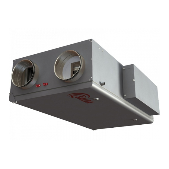
The unit can not be used as an air heater. Not suitable for swimming pools, saunas and other similar facilities. 4.2. DIMENSIONS AND WEIGHT Figure 4.2.1. RIS 400 PE 3.0; RIS 700 PE 3.0; RIS 1000 PE 3.0 RIS PE 3.0 øD Weigth... -
Page 6: Technical Data
4.3. TECHNICAL DATA RIS PE 3.0 1000 1500 phase/voltage [50 Hz/VAC] ~1, 230 ~1, 230 ~1, 230 ~1, 230 power/current [kW/A] 0,225/1,1 0,255/1,12 0,286/1,25 0,359/1,57 Exhaust air fan speed [min 1850 2000 2250 2750 protection class IP-44 IP-44 IP-44 IP-44 phase/voltage [50 Hz/VAC] ~1, 230... -
Page 7: Instalation
5. INSTALATION 5.1. RECEPTION OF GOODS Each device is thoroughly checked before transportation. While receiving goods it is recommended to check whether devices were not damaged during transportation. If a damage to the device is noticed, immediately address the representatives of a transport company. Please inform a rep- resentative of the manufacturer, if any deviation from the order is noticed. -
Page 8: Piping And Instrumentation Diagram
5.4. PIPING AND INSTRUMENTATION DIAGRAM Stouch Flex Figure 5.4.1. RIS 400 PE 3.0; RIS 700 PE 3.0 Stouch Flex Figure 5.4.2. RIS 1000 PE 3.0; RIS 1500 PE 3.0 LIST OF COMPONENTS temperature sensor for fresh air (supplied in set with in-... -
Page 9: Place Requirements For The Equipment And Mounting Positions
5.5.2. MOUNTING ON SEALING 0 -1 Figure 5.5.2.1. RIS 400 PE 3.0; RIS 700 PE 3.0 Figure 5.5.2.2. RIS 1000 PE 3.0; RIS 1500 PE 3.0 - Installing should only be performed by qualified and trained staff. - AHU are mounted to the ceiling using mounting elements (bolts, screws and etc.). It is needed to keep 1° inclination in drainage direction (picture below), do not mount AHU in opposite direction. -
Page 10: Drainage Installation
5.5.3. DRAINAGE INSTALLATION Before every heating season the condensate tube shall be filled with water as indicated during the first start-up! Before every heating season the condensate tube shall be filled with water as indicated during the first start-up! AHU (1) is built on a foundation in a such way that the side of AHU (1) with drainage exhaust pipe (2) is lower 0° - 3° than the other side (the con- crete max. -
Page 11: Start-Up Recommendations
5.8. START-UP RECOMMENDATIONS 5.8.1. SYSTEM PROTECTION The control automatics of the unit have integrated protection against a short circuit of those assemblies. The controllers have the following pro- tectors: F1, F2 - 1A(5x20) MCB protection; To ensure safe maintenance of the unit, it is necessary to turn off main switch and/or external protection device. 5.8.2. -
Page 12: Maintenance
FILTERS MAINTENANCE Changing filters, filters reload timer control. Description of remote control panel functions is provided in the remote control panel technical documentation or on the website www.salda.lt. Allowed to operate the unit without filters! It is advisable to change the filters every 3 - for 4 months, or according to their testimony timer remote control. -
Page 13: Heat Exchanger Maintenance
- Make sure, that impeller’s balance weights are not moved. - Make sure the impeller is not hindered. - Mount the fan back into the unit. Connect the fan to power supply source. - If the fan does not start after maintenance or repair, contact the manufacturer. Be sure the unit is disconnected from power source before performing any maintenance or repair. -
Page 14: Control
7. CONTROL Supply air temperature can be adjusted according to the temperature measured by the supply or extracted air temperature sensor and the temperature which is set by the user on the remote control panel. When the supply air temperature is lower than the set, bypass damper of the units RIS PE 1000 3.0 and RIS PE 1500 3.0 is closed and fresh outdoor air passes through a plate heat exchanger. -
Page 15: Using The Unit In Bms Network
7.2. USING THE UNIT IN BMS NETWORK The recuperator can be connected to the BMS network by using the ModBus protocol. The device can be controlled using FLEX panel and BMS network simultaneously: the device will work based on the latest changes of settings. As set in the factory, the device will operate (if no faults are present) based on the latest panel settings in case the panel or BMS network (or even both) is disconnected. -
Page 16: Electrical Connection Of The Hvac Unit
Filter 01h_Read_Coils Dirty filter alarm 1-active, o-passive Fans alarm 01h_Read_Coils 1-active, o-passive LowPower 01h_Read_Coils Low voltage 1-active, o-passive Textract 01h_Read_Coils DTJ(100) temperature sensor alarm 1-active, o-passive Texhaust 01h_Read_Coils Exhaust air temperature sensor alarm 1-active, o-passive Tlimit 01h_Read_Coils Supply air temperature sensor alarm 1-active, o-passive DTJ(100) humidity sensor alarm (controller works 01h_Read_Coils... -
Page 17: System Adjustment Guidelines
7.5. SYSTEM ADJUSTMENT GUIDELINES Before commissioning, device launching and adjustment works must be done only by qualified and trained personnel. Automatic control system of the ventilation unit must be properly adjusted to work adequately. Also, install measuring and operating devices in line with the provided guidelines. Air temperature sensors and air quality converters. -
Page 18: Led Indications Of The Controller Pic. 3A
7.7. LED INDICATIONS OF THE CONTROLLER PIC. 3A LED2 Air damper close LED9 Medium fans speed LED2+ LED3 Air damper open LED10 Minimal fans speed LED6 BYPASS LED11 Supply air fan speed reducing LED7 BYPASS LED12 Preheater LED8 Maximal fans speed LED13 Supply air heater 7.8. -
Page 19: Regular System Check-Up
Fans guard Extract air temperature sensor Temp. and humidity sensor for extract air. Extract air humidyti sensor Supply air temperature sensor Supply air temperature sensor. Exhaust air temperature sensor Exhaust air temperature sensor 7.9. REGULAR SYSTEM CHECK-UP The operation of the switching device (contactor) should be visually inspected every 3–4 months (the casing cannot be melted and should have no other signs of the thermal damage, no extra sounds should be generated while switching or during impact). -
Page 20: Accessories
8. ACCESSORIES RIS 400 PE 3.0; RIS 700 PE 3.0 RIS 1000 PE 3.0; RIS 1500 PE 3.0 Summer casette VK Spare filters FR Spare filters FR Fresh air damper SKM Pressure switch Extract air damper SKG Air damper SKG... -
Page 21: Electrical Connection Diagram
Water cooler Fire alarm Supply air Extract air Supply air Power DX Cooling supply cable Boost Start/Stop AHU stop AHU work input valve actuator damper actuator damper actuator temp.sensor Figure. 9.1. RIS 400 PE 3.0 RIS PE 3.0 v2020.1 EN |... - Page 22 XPE1.1 XPE1.1 XPE1.2 XPE1.2 XKE1.1 XKE1.1 XKE1.1 XKE1.2 XKE1.2 XKE1.2 XKE1.1 XKE1.2 X32.1 X32.4 X35.2 120V AC.N PUMP X35.1 230V B.0.10 X33.13 X33.14 170V MIDL X32.2 140V BOOST HIGH X32.3 TIME X33.15 START-NC STOP-NO X33.2 CHIL X33.9 X33.10 Fan fall ALARM X33.11 1.2W max...
- Page 23 230V AC 24VAC, 3-position 230V AC Y1 - Control OPEN (AC 24 V) 1.822.0066B.0.1.0-L-0k Y2 - Control CLOSE (AC 24 V) ON/OFF ON/OFF N L L G - System potential AC 24 V X16.1 17 18 X16.5 L1 L2 L3 X21.3 24VAC X22.1...
- Page 24 Figure. 9.4. RIS 1500 PE 3.0 | EN RIS PE 3.0 v2020.1...
- Page 25 Figure. 9.5. RIS 1500 PE 3.0 RIS PE 3.0 v2020.1 EN |...
- Page 26 Figure. 9.6. RIS 1500 PE 3.0 W9\green/yellow W9\black W9\blue 0,28kW W9\brown 2750 min-1 W10\green/yellow W10\black W10\blue 0,28kW W10\brown 2750 min-1 Figure. 9.7. RIS 1500 PE 3.0 Figure. 9.8. RIS 1500 PE 3.0 | EN RIS PE 3.0 v2020.1...
- Page 27 Figure. 9.9. RIS 1500 PE 3.0 RIS PE 3.0 v2020.1 EN |...
-
Page 28: Possible Faults And Troubleshooting
10. POSSIBLE FAULTS AND TROUBLESHOOTING FAILURE CAUSE EXPLANATION / CORRECTIVE ACTIONS Check whether the device is connected to the No supply voltage power network Switch on only if the unit condition has been Unit is not operating Protection device is off or a current evaluated by a qualified electrician. -
Page 29: Warranty
3.4. when the unit was used not for its original purpose. 3.5. Company SALDA UAB is not responsible for potential loss of property or personal injury in cases where AHU is manufactured without a con- trol system and the control system will be installed by the client or third parties. The manufacturer’s warranty does not cover devices that will be damaged by installing the control system. - Page 30 RIS PE 3.0 v2020.1...
- Page 31 RIS PE 3.0 v2020.1...
- Page 32 Heat exchanger cleaning Every 3-4 Filter replacement months** Look at the product label. ** - At least. NOTE. The purchaser is required to fill in the “Product maintenance table”. MAN000302 MAN000302 Ragainės g. 100 +370 41 540 415 Šiauliai LT-78109, LITHUANIA office@salda.lt...
Need help?
Do you have a question about the RIS 400 PE 3.0 and is the answer not in the manual?
Questions and answers