
Related Manuals for Mitsubishi MELFA RH-6SH Series


Summary of Contents for Mitsubishi MELFA RH-6SH Series
- Page 1 Mitsubishi Industrial Robot RH-6SH/12SH/18SH Series Standard Specifications Manual (CR1B-571/CR2B-574/CR3- 535M Controller) BFP-A8416-E...
- Page 3 Precautions for Using the FINE Instruction Thank you for your purchasing of our Mitsubishi Electric industrial robots. This document describes additional precautions relating to the specification in the RH-6SH/12SH/18SH Series Standard Specification manual (BFP-A8416). Please be sure to read this document before using the robot for thorough understanding of the contents.
- Page 4 (4) Guideline for FINE Conversion (Reference) It will be equal with RH-A and RH-SH, in FINE setting conversion equation 1. B = (1 + A) x 16 – 1 . . . (Equation 1) A = "FINE setting value of RH-A series" B = "FINE setting value of RH-SH series"...
- Page 5 Safety Precautions Always read the following precautions and the separate "Safety Manual" before starting use of the robot to learn the required measures to be taken. CAUTION All teaching work must be carried out by an operator who has received special training.
- Page 6 The points of the precautions given in the separate "Safety Manual" are given below. Refer to the actual "Safety Manual" for details. CAUTION Use the robot within the environment given in the specifications. Failure to do so could lead to a drop or reliability or faults. (Temperature, humidity, atmosphere, noise environment, etc.) CAUTION Transport the robot with the designated transportation posture.
- Page 7 CAUTION Do not stop the robot or apply emergency stop by turning the robot control- ler's main power OFF. If the robot controller main power is turned OFF dur- ing automatic operation, the robot accuracy could be adversely affected.Moreover, it may interfere with the peripheral device by drop or move by inertia of the arm.
- Page 8 ■ Revision history Date of print Specifications No. Details of revisions 2004-07-07 BFP-A8416 First print. 2006-07-12 BFP-A8416-A Error in writing correction. 2007-07-10 BFP-A8416-B Error in writing correction. 2009-06-23 BFP-A8416-C The EC Declaration of Conformity was changed. (Correspond to the EMC directive; 2004/108/EC) 2009-07-29 BFP-A8416-D The EC-Statement of Compliance was added.
- Page 9 The RH-6SH/12SH/18SH series offers small-size industrial robots developed using Mitsubishi's latest technol - ogy. They are especially designed to handle and assemble mechanical parts. They are Mitsubishi's answer to the customer's need to achieve a compact manufacturing facility capable of highly flexible production, as necessitated by the diffusion of high-density product groups and the shorter product life cycles that have become common - place in recent years.
-
Page 10: Table Of Contents
Contents Page 1 General configuration ....................................1-1 1.1 Structural equipment .................................... 1-1 1.1.1 Standard structural equipment ..............................1-1 1.1.2 Shipping special specifications ..............................1-1 1.1.3 Options ....................................... 1-1 1.1.4 Maintenance parts ..................................1-1 1.2 Model type combination of robot ..............................1-2 1.2.1 How to identify the robot model .............................. - Page 11 Contents Page 2.5 Tooling ........................................2-55 2.5.1 Wiring and piping for hand ................................ 2-55 2.5.2 Internal air piping ..................................2-56 2.5.3 Internal wiring for the pneumatic hand output cable ....................2-56 2.5.4 Internal wiring for the hand check input cable ....................... 2-56 2.5.5 Spare wiring ....................................
- Page 12 Contents Page (13) Personal computer support software/Personal computer support software mini ......... 3-154 (14) Instruction Manual(bound edition) ..........................3-156 3.11 Maintenance parts ..................................3-157 4 Software ........................................4-158 4.1 List of commands ..................................... 4-158 (1) MELFA-BASIC Ⅳ commands ............................4-159 4.2 List of parameters ....................................
-
Page 13: General Configuration
1General configuration 1 General configuration 1.1 Structural equipment Structural equipment consists of the following types. 1.1.1 Standard structural equipment The following items are enclosed as a standard. (1) Robot arm (2) Controller (3) Machine cable (4) Robot arm installation bolts (5) Earth leakage breaker (CR1B-571 only) (6) Safety manual, CD-ROM (Instruction manual) (7) Guarantee card... -
Page 14: Model Type Combination Of Robot
1General configuration 1.2 Model type combination of robot The model names of the RH-SH series are determined according to the load capacity, arm length, up/down stroke length and environment specification. The details are shown below; please select a robot that suits your intended purposes. - Page 15 1General configuration (g). -S3 00........[1] Indicates a special model number. (A) (B) (A). -S3: Indicates that the special model number is between 300 and 599. Note that numbers in the three hundred-range indicate combinations of the RH-6SH series and the CR2B-574 controller.
-
Page 16: Combinations Of Robot Arms And Controllers
1General configuration 1.2.2 Combinations of robot arms and controllers Table 1-2 : List of combinations of robot arms and controllers Arm length Up/dpwn stroke Environment specifications Robot arm Controller (mm) length (mm) RH-6SH seires Standard specification RH-6SH3520 RH-6SH4520 RH-6SH5520 Clean specification RH-6SH3517C RH-6SH4517C CR1B-571... -
Page 17: Contents Of The Structural Equipment
1General configuration 1.6 Contents of the structural equipment 1.6.1 Robot arm The devices shown below can be installed on the robot arm. Machine cable Horizontal four-axis multiple-jointed type (Fixed type: 5m) (RH-6SH series) Machine cable (Fixed type: 2m) ・ 1S-02UCBL-03 Machine cable extension Fixed type: ・... - Page 18 1General configuration Machine cable Horizontal four-axis multiple-jointed type (Fixed type: 5m) (RH-12SH/18SH series) Machine cable (Fixed type: 2m) ・ 1S-02UCBL-01 Machine cable extension Fixed type: ・ 1S- □□ CBL-01 Flexed type: ・ 1S- □□ LCBL-01 Note1) □□ refer the length. Refer to Page 9, "1.7 Contents of the RH-12SH*/12SH*C/12SH*M...
-
Page 19: Controller
1General configuration 1.6.2 Controller The devices shown below can be installed on the controller. 1.6.3 CR1B-500 series controller Controller ・ CR1B-571 Controller protection box Teaching pendant ・ CR1-MB (T/B) ・ R28TB *1) This is provided as standard for the specification with the controller protection box. -
Page 20: Cr2B-500/Cr3-500 Series Controller
1General configuration 1.6.4 CR2B-500/CR3-500 series controller Controller Controller Caster specification Teaching pendant ・ CR2B-574 ・ CR3-535M controller (T/B) (Protection specification) ・ R28TB *1)"-SM" specification (Pro - tection specification) is the CR3-535M controller. Parallel I/O unit External I/O cable Pneumatic I/F ・... -
Page 21: Contents Of The Option Equipment And Special Specification
1General configuration 1.7 Contents of the Option equipment and special specification A list of all Optional equipments and special specifications are shown below. Table 1-4 : RH-6SH Series: List of Optional Devices and Special Specifications for the CR1B-571 Controller Classifica Item Type Specifications... - Page 22 1General configuration Table 1-4 : (Continued) RH-6SH Series: List of Optional Devices and Special Specifications for the CR1B-571 Controller Classifi - Item Type Specification cation Descripsion Note1) Instruction Manual A set of the instructions manual bookbinding Note2) 4S-MAP-107 ○ For the CR1B-571 controller editions.
- Page 23 1General configuration Table 1-5 : RH-12/18SH Series: List of Optional Devices and Special Specifications for the CR2B-574/CR3-535M Controller Classifi Item Type Specifications cation Descripsion Note1) Machine cable(Replaced with 1S-02UCBL-01 For fixing 2m(A 2 m cable is supplied instead of the 5 m cable ○...
- Page 24 1General configuration Table 1-5: RH-12/18SH Series: List of Optional Devices and Special Specifications for the CR2B-574/CR3-535M Controller (Continued) Classifi - Item Type Specification cation Descripsion Note1) Instruction Manual 4S-MAP-108 ○ For the CR2B-574 controller A set of the instructions manual bookbinding editions.
-
Page 25: Robot Arm
2Robot arm 2 Robot arm 2.1 Standard specifications 2.1.1 RH-6SH series Table 2-1 : Tab Standard specifications of robot (Standard Specification) Item Unit Specifications Type RH-6SH3520 RH-6SH4520 RH-6SH5520 Environment Standard specification Installation posture On floor Degree of freedom Structure Horizontal, multiple-joint type Drive system AC servo motor Position detection method... - Page 26 2Robot arm Table 2-2 : Tab Standard specifications of robot (Clean Specification) Specifications Item Unit Type RH-6SH3517C RH-6SH4517C RH-6SH5517C Environment Clean specification Installation posture On floor Degree of freedom Structure Horizontal, multiple-joint type Drive system AC servo motor Position detection method Absolute encoder Motor capacity W...
- Page 27 2Robot arm Table 2-3 : Tab Standard specifications of robot (Oil mist Specification) Specifications Item Unit Type RH-6SH3517M RH-6SH4517M RH-6SH5517M Environment Oil mist specification Installation posture On floor Degree of freedom Structure Horizontal, multiple-joint type Drive system AC servo motor Position detection method Absolute encoder Motor capacity...
-
Page 28: Rh-12Sh Sereis
2Robot arm 2.1.2 RH-12SH sereis Table 2-4 : Tab Standard specifications of robot (Standard Specification) Item Unit Specifications Type RH-12SH5535 RH-12SH7035 RH-12SH8535 Environment Standard specification Installation posture On floor Degree of freedom Structure Horizontal, multiple-joint type Drive system AC servo motor Position detection method Absolute encoder Motor capacity... - Page 29 2Robot arm Table 2-5 : Tab Standard specifications of robot (Clean Specification) Item Unit Specifications Type RH-12SH5530C RH-12SH7030C RH-12SH8530C Environment Clean specification Installation posture On floor Degree of freedom Structure Horizontal, multiple-joint type Drive system AC servo motor Position detection method Absolute encoder Motor capacity W...
- Page 30 2Robot arm Table 2-6 : Tab Standard specifications of robot (Oil mist Specification) Item Unit Specifications Type RH-12SH5530M RH-12SH7030M RH-12SH8530M Environment Oil mist specification Installation posture On floor Degree of freedom Structure Horizontal, multiple-joint type Drive system AC servo motor Position detection method Absolute encoder Motor capacity...
-
Page 31: Rh-18Sh Series
2Robot arm 2.1.3 RH-18SH series Table 2-7 : Tab Standard specifications of robot Item Unit Specifications Type RH-18SH8535 RH-18SH8530C RH-18SH8530M Environment Standard specification Clean specification Oil mist specification Installation posture On floor Degree of freedom Structure Horizontal, multiple-joint type Drive system AC servo motor Position detection method Absolute encoder... -
Page 32: Definition Of Specifications
2 Robot arm 2.2 Definition of specifications The accuracy of pose repeatability mentioned in catalogs and in the specification manual is defined as follows. 2.2.1 Pose repeatability For this robot, the pose repeatability is given in accordance with JIS 8432 (Pose repeatability). Note that the value is based on 100 measurements (although 30 measurements are required according to JIS). -
Page 33: Mass Capacity And The Allowable Moment
2 Robot arm 2.2.2 Mass capacity and the allowable moment The robot's mass capacity is expressed solely in terms of mass, but even for tools and works of similar mass, eccentric loads will have some restrictions. When designing the tooling or when selecting a robot, consider the fol - lowing issues. - Page 34 2 Robot arm Unit : mm Shaft center Allowable moment of inertia Maximum: Rating Fig.2-2 : Position of center of gravity for loads (for loads with comparatively small volume): RH-12SH series Unit : mm Shaft center Allowable moment of inertia Maximum: Rating Fig.2-3 :...
-
Page 35: Relationships Among Mass Capacity, Speed, And Acceleration/Deceleration Speed
2 Robot arm 2.2.3 Relationships Among Mass Capacity, Speed, and Acceleration/Deceleration Speed This robot automatically sets the optimum acceleration and deceleration speeds and maximum speed, according to the load capacity and size that have been set, and operates using these automatically set speeds. In order to achieve this, it is necessary to set the actual load used. -
Page 36: Relationship Between Mass Capacity And Speed
2 Robot arm (2) Relationship Between Mass Capacity and Speed A function to optimize the maximum speed of each axis according to the setting value of the load capacity will be activated (Refer to Fig. 2-4). However, this function does not work with the setting of 2kg (5kg in the case of RH- 18SH85 sereis) or lighter load mass. -
Page 37: Time To Reach The Position Repeatability (Only For Rh-12Sh/18Sh Series)
2 Robot arm (4) Time to reach the position repeatability (only for RH-12SH/18SH series) When using this robot, the time to reach the position repeatability may be prolonged due to the effect of residual vibration at the time of stopping. If this happens, take the following measures: 1) Change the operation position of the Z axis to the location near the top as much as possible. -
Page 38: Protection Specifications And Working Environment
The IEC IP symbols define the degree of protection against solids and fluids, and do not indicate a protective structure against the entry of oil or water. The evaluation regarding oil mist specifications has been confirmed with Mitsubishi's standard testing methods using the cutting oils shown in Table 2-9. -
Page 39: About The Use With The Bad Environment
2 Robot arm (2) About the use with the bad environment This robot has protection methods that conform to IEC's IP54 standards (splashproof type). It has protection structure designed to prevent harmful effects caused by splashing water coming from various directions, as the robot is operating. -
Page 40: Clean Specifications
* If any vacuum pump is prepared by the customer, assure on the vacuum side flow rate 60 liters/min.(ANR) or more . 3) When using the Mitsubishi standard option solenoid valve set, use the spare piping (φ6 pneumatic hose) of the primary piping to exhaust the air. -
Page 41: Names Of Each Part Of The Robot
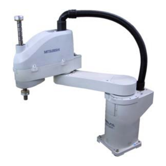
2 Robot arm 2.3 Names of each part of the robot Brake release switch (J3-axis) J2-axis J4-axis Cable - + - + J1-axis Shaft + J3-axis - + No.1 arm - No.2 arm Base Fig.2-8 : Names of each part of the robot Names of each part of the robot 2-29... -
Page 42: Outside Dimensions ・ Operating Range Diagram
2 Robot arm 2.4 Outside dimensions ・ Operating range diagram 2.4.1 Outside dimensions ・ Operating range diagram (RH-6SH series) (1) Srandard Specification Installation surface Machine cable Note View A *1 indicates the dimension when the solenoid valve (optional) is mounted. *2 indicates the space necessary to connect machine cables. - Page 43 2 Robot arm Installation surface Machine cable Note *1 indicates the dimension when the solenoid valve (optional) is mounted. View A *2 indicates the space necessary to connect machine cables. *3 indicates screw holes (M4) for fixing user wiring/piping. *4 indicates the dimension from the inlet for the NO2 arm cover to the upper edge of the mechanical stopper of axis J3. *5 indicates screw holes for mounting the solenoid valve box (optional).
- Page 44 2 Robot arm Installation surface Machine cable Note View A *1 indicates the dimension when the solenoid valve (optional) is mounted. *2 indicates the space necessary to connect machine cables. *3 indicates screw holes (M4) for fixing user wiring/piping. *4 indicates the dimension from the inlet for the NO2 arm cover to the upper edge of the mechanical stopper of axis J3. *5 indicates screw holes for mounting the solenoid valve box (optional).
-
Page 45: Clean Specification
2 Robot arm (2) Clean Specification Installation surface View A Machine cable Note *1 indicates the dimension when the solenoid valve (optional) is mounted. Primary air supply port *2 indicates the space necessary to connect machine cables. and dust suction port *3 indicates screw holes (M4) for fixing user wiring/piping. - Page 46 2 Robot arm Installation surface View A Machine cable Note *1 indicates the dimension when the solenoid valve (optional) is mounted. Primary air supply port *2 indicates the space necessary to connect machine cables. and dust suction port *3 indicates screw holes (M4) for fixing user wiring/piping. *4 indicates screw holes for mounting the solenoid valve box (optional).
- Page 47 2 Robot arm Installation surface View A Machine cable Note *1 indicates the dimension when the solenoid valve (optional) is mounted. *2 indicates the space necessary to connect machine cables. *3 indicates screw holes (M4) for fixing user wiring/piping. *4 indicates screw holes for mounting the solenoid valve box (optional). Note) Refer to Fig.
-
Page 48: Oil Mist Specification
2 Robot arm (3) Oil mist Specification Installation surface Machine cable Note View A *1 indicates the dimension when the solenoid valve (optional) is mounted. *2 indicates the space necessary to connect machine cables. *3 indicates screw holes (M4) for fixing user wiring/piping. *4 indicates screw holes for mounting the solenoid valve box (optional). - Page 49 2 Robot arm Installation surface Machine cable Note View A *1 indicates the dimension when the solenoid valve (optional) is mounted. *2 indicates the space necessary to connect machine cables. *3 indicates screw holes (M4) for fixing user wiring/piping. *4 indicates screw holes for mounting the solenoid valve box (optional). Note) Refer to Fig.
- Page 50 2 Robot arm Installation surface Machine cable View A Note *1 indicates the dimension when the solenoid valve (optional) is mounted. *2 indicates the space necessary to connect machine cables. *3 indicates screw holes (M4) for fixing user wiring/piping. *4 indicates screw holes for mounting the solenoid valve box (optional). Note) Refer to Fig.
-
Page 51: Outside Dimensions ・ Operating Range Diagram Of Rh-12Sh Series
2 Robot arm 2.4.2 Outside dimensions ・ Operating range diagram of RH-12SH series (1) Srandard Specification Installation surface View A View B Machine cable Primary air supply port Note View C *1 indicates the dimension when the solenoid valve (optional) is mounted. *2 indicates the space necessary to connect machine cables. - Page 52 2 Robot arm Installation surface View A View B Machine cable Primary air supply port Note View C *1 indicates the dimension when the solenoid valve (optional) is mounted. *2 indicates the space necessary to connect machine cables. *3 indicates screw holes (M4) for fixing user wiring/piping. *4 indicates the dimension from the inlet for the NO2 arm cover to the upper edge of the mechanical stopper of axis J3.
- Page 53 2 Robot arm Installation surface View A View B Machine cable Primary air supply port Note View C *1 indicates the dimension when the solenoid valve (optional) is mounted. *2 indicates the space necessary to connect machine cables. *3 indicates screw holes (M4) for fixing user wiring/piping. *4 indicates the dimension from the inlet for the NO2 arm cover to the upper edge of the mechanical stopper of axis J3.
-
Page 54: Clean Specification
2 Robot arm (2) Clean Specification Installation surface View B Machine cable Primary air supply port and dust suction port Note *1 indicates the dimension when the solenoid valve (optional) is mounted. *2 indicates the space necessary to connect machine cables. *3 indicates screw holes (M4) for fixing user wiring/piping. - Page 55 2 Robot arm Installation surface View B Machine cable Primary air supply port and dust suction port Note *1 indicates the dimension when the solenoid valve (optional) is mounted. *2 indicates the space necessary to connect machine cables. *3 indicates screw holes (M4) for fixing user wiring/piping. View C *4 indicates screw holes for mounting the solenoid valve box (optional).
- Page 56 2 Robot arm Installation surface View B Machine cable Primary air supply port and dust suction port Note *1 indicates the dimension when the solenoid valve (optional) is mounted. *2 indicates the space necessary to connect machine cables. *3 indicates screw holes (M4) for fixing user wiring/piping. *4 indicates screw holes for mounting the solenoid valve box (optional).
-
Page 57: Oil Mist Specification
2 Robot arm (3) Oil mist Specification Installation surface View B Machine cable Primary air supply port Note View C *1 indicates the dimension when the solenoid valve (optional) is mounted. *2 indicates the space necessary to connect machine cables. *3 indicates screw holes (M4) for fixing user wiring/piping. - Page 58 2 Robot arm Installation surface View B Machine cable Primary air supply port Note View C *1 indicates the dimension when the solenoid valve (optional) is mounted. *2 indicates the space necessary to connect machine cables. *3 indicates screw holes (M4) for fixing user wiring/piping. *4 indicates screw holes for mounting the solenoid valve box (optional).
- Page 59 2 Robot arm Installation surface View B Machine cable Primary air supply port Note View C *1 indicates the dimension when the solenoid valve (optional) is mounted. *2 indicates the space necessary to connect machine cables. *3 indicates screw holes (M4) for fixing user wiring/piping. *4 indicates screw holes for mounting the solenoid valve box (optional).
-
Page 60: Outside Dimensions ・ Operating Range Diagram Of Rh-18Sh Series
2 Robot arm 2.4.3 Outside dimensions ・ Operating range diagram of RH-18SH series (1) Srandard Specification Installation surface View A View B Machine cable Primary air supply port Note View C *1 indicates the dimension when the solenoid valve (optional) is mounted. *2 indicates the space necessary to connect machine cables. -
Page 61: Clean Specification
2 Robot arm (2) Clean Specification Installation surface View B Machine cable View C Primary air supply port and dust suction port Note *1 indicates the dimension when the solenoid valve (optional) is mounted. *2 indicates the space necessary to connect machine cables. *3 indicates screw holes (M4) for fixing user wiring/piping. -
Page 62: Oil Mist Specification
2 Robot arm (3) Oil mist Specification Installation surface View B Machine cable Primary air supply port Note *1 indicates the dimension when the solenoid valve (optional) is mounted. View C *2 indicates the space necessary to connect machine cables. *3 indicates screw holes (M4) for fixing user wiring/piping. -
Page 63: Mechanical Interface And Installation Surface
2 Robot arm 2.4.4 Mechanical interface and Installation surface (1) Mechanical interface and Installation surface of RH-6SH sereis φ14 through hole φ20h7 Section of Z-Z φ39.5 Detail of Mechanical interface 4-φ9(Installation hole) Installation reference surface 6.3a Installation dimension details Fig.2-30 : Mechanical interface and Installation surface of RH-6SH series Outside dimensions ・... -
Page 64: Mechanical Interface And Installation Surface Of Rh-12Sh/18Sh Series
2 Robot arm (2) Mechanical interface and Installation surface of RH-12SH/18SH series φ18 through hole φ25h7 φ50 Section of Z-Z Detail of Mechanical interface Installation reference surface 6.3a 4-φ16(Installation hole) Installed using M12 x 40 provided Installation dimension details Fig.2-31 : Mechanical interface and Installation surface of RH-12SH/18SH series Outside dimensions ・... -
Page 65: Change The Operating Range
2 Robot arm 2.4.5 Change the operating range The operating ranges of both the J1 and J2 axes can be limited. Change the mechanical stopper and the operating range to be set inside of that area. If the operating range must be limited for example, to avoid interference with peripheral devices or to ensure safety--set up the operating range as shown below. -
Page 66: Changing The Operating Range
2 Robot arm (2) Changing the operating range ■ Installing the mechanical stopper 1) Turn the controller power OFF. 2) Refer to Table 2-12 Fig. 2-32 Fig. 2-33, install the hexagonal socket head bolts in the screw holes corresponding to the angles to be set. Fig. -
Page 67: Tooling
2 Robot arm 2.5 Tooling 2.5.1 Wiring and piping for hand Shows the wiring and piping configuration for a standard-equipped hand. Spare piping, electrical wiring opening Grommet(φ21.5) Solenoid valve set(optional) installation section Secondary piping pneumatic hose (customer-prepared) RH-6SH series:φ4 RH-12SH/18SH series:φ6 「GR1」、「GR2」... -
Page 68: Internal Air Piping
2 Robot arm 2.5.2 Internal air piping (1) Two φ6 x 4 urethane hoses are piped internally from the air intake opening at the base part to the rear part of the No. 2 arm. (2) Two air joints for φ6 hoses are attached at the hose edge area on both the base side and No. 2 arm side. (3) One φ8 hose joint (VACUUM) is dedicated to centralized suction in the case of the clean specification only. -
Page 69: Precautions For Piping To The Flexible Cable
2 Robot arm 2.5.6 Precautions for piping to the flexible cable If the piping of the hand is performed to the flexible cable of this robot, be sure to perform wiring and piping by fol - lowing the precautions listed below so that they will not interfere with the functionality of the flexible cable. Point: When installing to the flexible cable, be sure to allocate some room. -
Page 70: About The Installation Of Tooling Wiring And Piping (Examples Of Wiring And Piping)
2 Robot arm 2.5.7 About the Installation of Tooling Wiring and Piping (Examples of Wiring and Piping) The customer is required to provide tooling wiring, piping and metal fixtures. Screw holes are provided on the robot arm for the installation of tooling wiring, piping and metal fixtures. (Refer to Table 2-35, Table 2-36... - Page 71 2 Robot arm RH-18SH series φ50 View from A View from B 2-M4 screw 2-M4 screw View from C 3-M4 screw 2-M4 screw (also provided on the opposite side) 3-M4 screw * The dimension is 33 mm for the clean/oil mist specifications. Fig.2-37 :...
-
Page 72: Example Of Wiring And Piping <1
2 Robot arm (1) Example of wiring and piping <1> This method is effective when the rotation of the hand is small (within ± 90 deg.) and provides easy maintenance of the robot arm as well as during the replacement of wiring and piping. Point: 2 When the robot is in operation, the wiring and piping must be at the position... -
Page 73: Precautions For The Oil Mist Specification And Clean Specification
2 Robot arm (3) Precautions for the oil mist specification and clean specification ・ Bellows are attached to the tips so confirm not interfering in the tooling wiring, piping, and the flexible tube. ・ Please use wiring materials that are sufficiently flexible. Furthermore, please perform the wiring in such a way that the bending radii of the selection tube and wires will not become less than the minimum values allowed while the robot is operating. -
Page 74: Wiring And Piping System Diagram For Hand
2 Robot arm 2.5.8 Wiring and piping system diagram for hand Shows the wiring and piping configuration for a standard-equipped hand. Hand signal input connection connector 1-1318115-3 (Tyco Electronics AMP) Hand signal input connector (HC1 connector) 1-1717834-3 (Tyco Electronics AMP) White <+24V>... - Page 75 2 Robot arm Hand signal input connection connector Hand signal input connection connector 1-1318115-3 1-1318115-3 (Tyco Electronics AMP) (Tyco Electronics AMP) Hand signal input connector (HC1 connector) Hand signal input connector (HC1 connector) 1-1717834-3 1-1717834-3 (Tyco Electronics AMP) (Tyco Electronics AMP) White White <+24G(RG)>...
-
Page 76: Electrical Specifications Of Hand Input/Output
2 Robot arm 2.5.9 Electrical specifications of hand input/output Table 2-13 : Electrical specifications of input circuit Item Specifications Internal circuit Type DC input <Sink type> No. of input points Insulation method Photo-coupler insulation Rated input voltage 12VDC/24VDC Rated input current Approx. -
Page 77: Air Supply Circuit Example For The Hand
2 Robot arm 2.5.10 Air supply circuit example for the hand Fig. 2-42 shows an example of pneumatic supply circuitry for the hand. (1) Place diodes parallel to the solenoid coil. (2) When the factory pneumatic pressure drops, as a result of the hand clamp strength weakening, there can be damage to the work. -
Page 78: Shipping Special Specifications, Options, And Maintenance Parts
2 Robot arm 2.6 Shipping special specifications, options, and maintenance parts 2.6.1 Shipping special specifications ■ What are sipping special specifications? Shipping special specifications are changed at the time of shipment from the factory. Consequently, customer need to confirm the delivery date. To make changes to the specifications after shipment, service work must be performed at the work site or the robot must be returned for service. -
Page 79: Machine Cable
2 Robot arm (1) Machine cable ■ Order type: RH-6SH series......● Fixed type(2m) 1S-02UCBL-03 RH-12SH/18SH series ....● Fixed type(2m) 1S-02UCBL-01 ■ Outline This cable is exchanged for the machine cable (5 m for fixed type) that was supplied as standard to shorten the distance between the controller and the robot arm. ■... -
Page 80: Options
2 Robot arm 2.7 Options ■ What are options? There are a variety of options for the robot designed to make the setting up process easier for customer needs. customer installation is required for the options. Options come in two types: "set options" and "single options". 1. -
Page 81: Machine Cable Extension
2 Robot arm (1) Machine cable extension ■ Order type : RH-6SH series..... ● Fixed type 1S- □□ CBL-03 ● Flexed type 1S- □□ LCBL-03 RH-12SH/18SH series ..● Fixed type 1S- □□ CBL-01 ● Flexed type 1S- □□ LCBL-01 Note) The numbers in the boxes □□... - Page 82 2 Robot arm ■ Cable configuration Table 2-18 shows the configuration of bending type cables of the RH-6SH series and Table 2-19 shows that of the RH-12SH/18SH series. Please use these as reference when selecting cable bearers. Table 2-18 : Cable configuration(RH-6SH series) Motor signal cable Motor power cable Item...
- Page 83 2 Robot arm RH-6SH series Robot arm CR1B-571 controller 1S-□□LCBL(P)-02 Nylon clamp NK-14N Nylon clamp NK-18N Nylon clamp 300 to 400mm NK-14N 300 to 400mm Nylon clamp 1S-□□LCBL(S)-01 NK-18N Extended flexible cable The fixed cable 5m (optional) (standard attachment) RH-12SH/18SH series Nylon clamp Extension section Silicon rubber...
-
Page 84: Solenoid Valve Set
2 Robot arm (2) Solenoid valve set ■ Order type: RH-6SH series ....● Four sets:1S-VD04M-04(Sink type)/1S-VD04ME-04(Source type) RH-12SH/18SH series ● Four sets:1S-VD04M-03(Sink type)/1S-VD04ME-03(Source type) ■ Outline The solenoid valve set is an option that is used for controlling toolings when various toolings, such as the hand, are installed at the end of the arm. - Page 85 2 Robot arm RH-6SH series <7><8> <9> <3> <6> <2> <1> <5> <4> 13.5 Part no. Part name Qty. Specifications <1> Solenoid valve <2> Manifold block <3> Quick coupling φ4 <4> Block plate <5> Quick coupling φ6 <6> Quick coupling φ6 <7>...
- Page 86 2 Robot arm RH-6SH series 4-M4 burring screw (Hole) (t1.6) 84.8 4-φ4.8 hole View from A (88) (50.6) Fig.2-45 : Outside dimensions of solenoid valve box (RH-6SH series) Options 2-74...
- Page 87 2 Robot arm RH-12SH/18SH series 87.9 <7><8> 37.8 50.1 <9> <3> <6> <2> <1> <5> <4> Part no. Part name Qty. Specifications <1> Solenoid valve <2> Manifold block <3> Quick coupling φ4 <4> Block plate <5> Quick coupling φ6 <6> Quick coupling φ6 <7>...
- Page 88 2 Robot arm RH-12SH/18SH series 4-M4 burring screw (Hole) View from A (t1.6) 4-φ4.8 hole (99.2) Fig.2-47 : Outside dimensions of solenoid valve box (RH-12SH/18SH series) Options 2-76...
-
Page 89: Hand Input Cable
2 Robot arm (3) Hand input cable ■ Order type:1S-HC35C-02 ■ Outline The hand input cable is used for customer-designed pneumatic hands. It is necessary to use this to receive the hand's open/close confirmation signals and grasping confirmation signals, at the controller. One end of the cable connects to the connector for hand input signals, which is in the No.2 arm back side. -
Page 90: Hand Output Cable
2 Robot arm (4) Hand output cable ■ Order type: 1S-GR35S-02 ■ Outline The hand output cable (solenoid valve connection cable) is an option that is used when an solenoid valve other than one of the solenoid valve set options, is used. One end of the cable has a connector that connects to the input terminal inside the robot. -
Page 91: Hand Curl Tube
2 Robot arm (5) Hand curl tube ■ Order type: RH-6SH series......... 1E-ST0408C-300 RH-12SH/18SH series....1N-ST0608C ■ Outline The hand curl tube is a curl tube for the pneumatic hand. ■ Configuration Part name Type Qty. Remarks Mass(kg) RH-6SH series Hand curl tube (Four set: 8 pcs.) 1E-ST0408C-300 1 pc. -
Page 92: Maintenance Parts
Timing belt J3 axis Mitsubishi Electric System & Service;Co.,Ltd. J4 axis motor side J4 axis shaft side Note1)Confirm the robot arm serial No., and contact the dealer or service branch of Mitsubishi Electric Co., for the type. Maintenance parts 2-80... -
Page 93: Controller
3Controller 3 Controller 3.1 Standard specifications 3.1.1 Standard specifications Table 3-1 : Standard specifications of controller (CR1B-571) Item Unit Specification Remarks Type CR1B-571 Number of control axis Simultaneously 4(Maximum) 64 bit RISC, and DSP Memory Programmed positions and No. point 2,500 capacity of steps... - Page 94 If you intend to use the controller in oil mist or dusty environments, please contact your nearest Mitsubishi branch or dealer. Install to the place not to influ - ence the cleanliness when using in the clean environment (Refer to Page 10, "2.2.6 Clean...
- Page 95 3Controller Table 3-3 : Standard specifications of controller (CR3-535M) Item Unit Specification Remarks Note1) Type CR3-535M Number of control axis Simultaneously 4(Maximum) 64 bit RISC, and DSP Memory Programmed positions and No. point 2,500 capacity of steps step 5,000 Number of programs Robot language MELFA-BASIC Ⅳ...
-
Page 96: Protection Specifications And Operating Supply
3Controller 3.1.2 Protection specifications and operating supply A protection method complying with the IEC Standard CR1B-571/CR2B-574: IP20(Opened type), CR3-535M: IP54(Closed type) is adopted for the controller. The IEC IP symbols refer only to the degree of protection between the solid and the fluids, and don't indicated that any special protection has been constructed for the prevention against oil and water. -
Page 97: Names Of Each Part
3Controller 3.2 Names of each part CR1B-571controller <Front> <Front side of operation panel> 7) 4) EMG.STOP STATUS NUMBER CHANG DISP DOWN MODE SVO ON START RESET TEACH AUTO AUTO REMOVE T/B (Op.) (Ext.) SVO OFF STOP Front operation panel 13) 3) CR2B-574 controller Front operation panel CR3-535M controller... - Page 98 3Controller 1) POWER switch........This turns the control power ON/OFF. 2) START button........This executes the program and operates the robot. The program is run continuously. 3) STOP button .........This stops the robot immediately. The servo does not turn OFF. 4) RESET button........This resets the error. This also resets the program's halted state and resets the program. 5) Emergency stop switch.....This stops the robot in an emergency state.
- Page 99 3Controller CR1B-571 controller Fig.3-2 : Names of each CR1B-571 controller part (Rear side) 1) Machine cable connector (for motor power) ..Connects to the robot arm base. (CN1 connector) 2) Machine cable connector (for motor signal) ... Connects to the robot arm base. (CN2 connector) 3)Power supply terminals.
- Page 100 3Controller CR3-535M controller Fig.3-4 : Names of each CR3-353M controller part (Rear side) 1) Machine cable (for motor power)......... Connects to the robot arm base. (CN1 connector) 2) Machine cable (for motor signal)........Connects to the robot arm base. (CN2 connector) Control unit (R6x2CPU) Fig.3-5 :...
-
Page 101: Outside Dimensions/Installation Dimensions
3Controller 3.3 Outside dimensions/Installation dimensions 3.3.1 Outside dimensions <CR1B-571> EMG.STOP STATUS NUMBER CHANG DISP DOWN MODE SVO ON START RESET TEACH AUTO AUTO REMOVE T/B (Op.) (Ext.) SVO OFF STOP (31) (31) (2.5) (2.5) Fig.3-6 : Outside dimensions of controller (CR1B-571 controller) Outside dimensions/Installation dimensions 3-89... - Page 102 3Controller <CR2B-574> 4-M5 screw Fig.3-7 : Outside dimensions of controller (CR2B-574 controller) Outside dimensions/Installation dimensions 3-90...
- Page 103 3Controller <CR3-535M> (55) Eye bolt 2-M10 (35) (50) 2×2-φ15 (40.5) (79.5) (15) (15) ←(When specifications with casters) Fig.3-8 : Outside dimensions of controller (CR3-353M controller) Outside dimensions/Installation dimensions 3-91...
- Page 104 3Controller <CR3-535M> Exhaust Suction Exhaust CN2 CN1 (7,000) (380) (Right side drawing) (Back drawing) Fig.3-9 : Outside dimensions of controller (CR3-353M controller)(Supplement) Outside dimensions/Installation dimensions 3-92...
-
Page 105: Installation Dimensions
3Controller 3.3.2 Installation dimensions 50mm 50mm EMG.STOP STATUS NUMBER CHANG DISP DOWN MODE SVO ON START RESET TEACH AUTO AUTO REMOVE T/B (Op.) (Ext.) SVO OFF STOP 170mm or more Fig.3-10 : Installation of controller (CR1B-571 controller) or more Horizontal placement CAUTION Use the rubber foot (4 positions) at the bottom of the controller as it is, or put the spacer, and leave the space between the installation side and the controller... - Page 106 3Controller <CR3-535M> Note1) Side Side Approx. Approx. Controller (upside) The mold cover for the RS-232C connector Maintenance area The rubber cover for the T/B connector (View from upside) (Anchor bolt installation: 4 places) Note1) The controller sucks in the outside air and discharges the inside air after cooling (Fig.
-
Page 107: External Input/Output
3Controller 3.4 External input/output 3.4.1 Types (1) Dedicated input/output.......These inputs and outputs carry out the robot remote operation and status display. (2) General-purpose input/output....These are inputs and outputs that the customer can program for peripheral device control. Moreover, it is possible to use parallel input/ output units and input/output signals via CC-Link. -
Page 108: Dedicated Input/Output
3Controller 3.5 Dedicated input/output Show the main function of dedicated input/output in the Table 3-4. Refer to attached instruction manual "Detailed explanations of functions and operations" in the product for the other functions. Each parameter indi - cated with the parameter name is used by designated the signal No., assigned in the order of input signal No. and output signal No. - Page 109 3Controller Input Output Parameter Note1) name Name Function Level Name Function IODATA Numeric value input Used to designate the program Used to output the program name, Numeric value output Note2) (start No., end No.) name, override value., mechanism L override value., mechanism No. (start No., end No.) value.
-
Page 110: Emergency Stop Input/Output
3Controller 3.6 Emergency stop input/output This signal is input from the "emergency stop input" terminal in the controller. Table 3-5 : Dedicated input terminals in controller Class Name Details Input Emergency stop Applies the emergency stop (CR1B-571:Single emergency line, CR2B-574/CR3-535M: Dual emergency line.) Input Door switch The servo turns OFF. - Page 111 3Controller [Caution] When wiring the emergency stop switch (duble emergency line type), wire both contacts to the two terminal blocks on the controller. If both contacts are wired to only one of the terminal blocks, errors cannot be cancelled using the door switch. Upside terminal block DOOR EMG.
- Page 112 3Controller [Caution] When wiring the emergency stop switch (duble emergency line type), wire both contacts to the two terminal blocks on the controller. If both contacts are wired to only one of the terminal blocks, errors cannot be cancelled using the door switch. EMG.
-
Page 113: Door Switch Function
3Controller 3.6.2 Door switch function This function retrieves the status of the switch installed on the door of the safety fence, etc., and stops the robot when the door is opened. This differs from an emergency stop in that the servo turns OFF when the door is opened and an error does not occur. -
Page 114: Additional Axis Function
A maximum of eight axes of servo motors can be controlled at the same time by connecting a general-purpose servo amplifier (MR-J2S-B, MR-J2M series) that supports Mitsubishi's SSC Net. Refer to the separate "Additional axis interface Instruction Manual" for details on the additional axis function. -
Page 115: Magnet Contactor Control Connector Output (Axmc) For Addition Axes
3Controller 3.8 Magnet contactor control connector output (AXMC) for addition axes Note1) When an additional axis is used, the servo ON/OFF status of the additional axis can be synchronized with the servo ON/OFF status of the robot itself by using the output contact (AXMC1) provided on the rear or inside of the controller and configuring a circuit so that the power to the servo amplifier for the additional axis can be turned off when this output is open. - Page 116 3Controller <Connector type> CR2A-572 controller of backside Plug side (user) : FRONT-MSTB2.5/2-STF-5.08 Socket side (controller) : DFK-MSTB2.5/2-GF-5.08 (Connector maker name : Phoenix Contact) Fig.3-20 : Arrangement figure of the AXMC1 connector (CR2B-574 controller) AXMC1 connector Enlargement Fig.3-21 : Arrangement figure of the AXMC1 connector (CR3-535M controller) Magnet contactor control connector output (AXMC) for addition axes 3-104...
-
Page 117: Parallel Input/Output Unit
3Controller 3.9 Parallel input/output unit ・ A parallel input/output card is mounted as a standard in the controller's control unit. ・ The external input/output circuit specifications are shown in Table 3-8 Table 3-9. ・ The pin numbers of external input/output connectors and the corresponding line colors of the connected "(1)Pin numbers of standard parallel input/output cards and sig - optional "external I/O cables"... - Page 118 3Controller [Caution] When connecting the phototransistor output to the input circuit, be sure to allocate an input current of approximately 7 mA at 24 VDC. Especially when using a photo diode and a phototransistor (sensor) away from each other, it is recommended to verify the current that can be carried in the design stage. CAUTION The output circuit protective fuses prevent failure in case of load short-circuit and improper connections.
- Page 119 (COM) Input 3.3K Input CTLG External power supply Fig.3-22 : Connection with a Mitsubishi PLC (Example of sink type) *The input/output circuit external power supply (24 VDC) must be prepared by the customer. <Source type> (Output) AX81C 60mA Fuse (24/12V) +24V...
- Page 120 3Controller (1) Pin numbers of standard parallel input/output cards and signal assignment(CR1B-571) Table 3-10 : Standard parallel I/O interface CN100pin No. and signal assignment list <Sink type> (2A-CBL □□ Function name Function name Line color Line color Dedicated/power supply, General-purpose Dedicated/power supply, common General-purpose common...
- Page 121 3Controller (2) Pin numbers of standard parallel input/output cards and signal assignment(CR2B-574) Table 3-12 : Standard parallel I/O interface CN100pin No. and signal assignment list (2A-CBL □□ Function name Function name Line color Line color Dedicated/power supply, General-purpose Dedicated/power supply, common General-purpose common 1 Orange/Red A...
- Page 122 3Controller ・The signals assigned as dedicated inputs can be used as general-purpose inputs during program execution. Note that for safety proposes, these should not be shared with the general-purpose inputs other than for numeric value inputs. The signals assigned as dedicated outputs cannot be used in the program. An alarm will occur dur - ing operation if used.
-
Page 123: Options
3Controller 3.10 Options ■ What are options? There are a variety of options for the robot designed to make the setting up process easier for user needs. User installation is required for the options. Options come in two types: "set options" and "single options". 1.... -
Page 124: Teaching Pendant (T/B)
In ISO/10218 (1992) and JIS-B8433 (1993), this is defined as an "enable device". These standards specify that the robot operation using the teaching pendant is enabled only when the "enable device" is at a specified position. With the Mitsubishi Electric industrial robot, the above "enable device" is configured of an "Enable/Disable switch" and "Deadman switch". - Page 125 3Controller Hand strap Contrast adjusting switch Enable/Disable switch Display LCD DISABLE ENABLE R28TB TOOL JOINT MENU STOP =* / ( )? $" : # % ! SVO ON EMG.STOP STEP - + MOVE (J1) (J1) Emergency stop - + + ↑...
- Page 126 3Controller ■ Key layout and main functions DISABLE ENABLE R28TB TOOL JOINT MENU STOP Back = */ ( )? $" : # % ! SVO ON EMG.STOP STEP - + MOVE (J1) (J1) - + ↑ + (J2) (J2) FORWD -...
-
Page 127: Pneumatic Hand Interface
3Controller (2) Pneumatic hand interface ■ Order type: 2A-RZ365(Sink type) 2A-RZ375(Source type) ■ Outline This interface is required to use the robot arm's hand output signals. This interface is pre-installed on the controller. ・ Up to eight hand output points can be used with this interface. ・... - Page 128 3Controller ■ Installation method This is mounted on the control unit in the controller. Securely insert the pneumatic hand interface (2A-RZ365/375) into the CNHNDOUT/CNHND connector on the control unit. Refer to separate "Instruction Manual/ Controller setup, basic operation, and maintenance" for details on the installing method.
- Page 129 3Controller Pneumatic hand interface RZ326A/327 card <RZ326A/327> CNHNDOUT CNHND CNHND CNHNDOUT 2A-RZ365/375 View A Fig.3-28 : Installation of pneumatic hand interface (CR2B-574 controller) Options 3-117...
- Page 130 3Controller Control unit (RZ181 card) <RZ181> CNHND CNHND CNHNDOUT 2A-RZ365 CNHNDOUT Jumper 2A-RZ375 Fig.3-29 : Installation of pneumatic hand interface (CR3-535M controller) Options 3-118...
-
Page 131: Controller Protection Box
3Controller (3) Controller protection box (CR1B-571 controller only) ■ Order type : ● CR1B-MB ■ Outline The controller protection box is used to protect the controller from an oil mist or other operating environment. Put the controller and the earth leakage breaker, etc. in controller protection box, and use it. - Page 132 3Controller ■ Names of each part <Front> <Rear> Cable cover Chassis cover (Top board) (Machine cable for power) Rear panel Heat exchanger Window Front panel Cable cover Corner type catch clip (Machine cable for signal) Fig.3-30 : Names of controller parts ■...
- Page 133 3Controller ■ The outside dimensions and installation dimensions of emergency stop box Operation switch BOX cover BOX base φ23.0 conduit 32.0 58.0 BOX cover installation screw (Knockout) 2-φ4.6 *The M4 screw prepared by customer (Two M4 installation screw holes) 58.0 Panel installation dimension Fig.3-32 :...
-
Page 134: Expansion Option Box
3Controller (4) Expansion option box (CR1B-571 controller only) ■ Order type : ● CR1-EB3 ■ Outline By installing this expansion option box to the side of the controller, the expansion serial interface, CC-Link interface, Ethernet interface, Addtional interface and PROFIBUS interface can be used. Up to three option cards can be mounted. - Page 135 3Controller Installation of expansion option box Controller Expansion option box Positioning latch Positioning latch Rear side cable outlet 299.7 (38) 87.5 (13) Installation screw Four positions Layout of expansion option box Slot1 Plates with rails Controller connection connector Slot2 (Two positions) Slot3...
-
Page 136: Parallel I/O Unit
3Controller (5) Parallel I/O unit ■ Order type: 2A-RZ361(Sink type) 2A-RZ371(Source type) ■ Outline This is used to expand the external inputs and outputs. ・ The connection cable is not included. Prepare the optional external input/output cable (2A-CBL05 or 2A-CBL15). ・... - Page 137 3Controller Table 3-25 : Electrical specifications for the output circuits Item Specification Internal circuit Type Transistor output <Sink type> No. of output points Insulation method Photo-coupler insulation (24/12V) Rated load voltage 12VDC/24VDC Rated load voltage range 10.2 to 30VDC(peak voltage 30VDC) Max.
- Page 138 3Controller NETcable-1 (Network cable) Pin No. RIO1/2 RIO1/2 Pin No. Note 2) 1 TXRXH TXRXH 1 2 TXRXL TXRXL 2 3 SG(GND) SG(GND) 3 DCcable-2 (Power cable) Pin No. DCIN Note 1) 1 + 24V Power 2 24G(RG) - 3 FG(PE) Connected the frame ground or protect ground R-TM (Terminator)
- Page 139 3Controller ■ Installation method The expansion parallel input/output unit is installed outside of the controller. Connect with the network connec - tion cable (NETcable-1) from the RIO1 connector in the rear of the controller. RIO1 connector upside (175) (40) Wiring space 2-M5...
- Page 140 3Controller RIO1 connector upside (40) (175) Wiring space 2-M5 screw <2A-RZ361> <2A-RZ371> Control panel installation dimensions downside Installation dimensions of 2A-RZ361/2A-RZ371 (The controller outside installation.) Fig.3-37 : Installing the parallel input/output unit (CR2B-574 controller) Options 3-128...
- Page 141 3Controller RIO1 connector Control unit (R6x2CPU) upside (40) (175) Wiring space 2-M5 screw <2A-RZ361> <2A-RZ371> Control panel installation dimensions downside The controller outside installation. Installation dimensions of 2A-RZ361/2A-RZ371 Fig.3-38 : Installing the parallel input/output unit (CR3-535M controller) Options 3-129...
- Page 142 3Controller RIO1 connector Parallel I/O unit 1 . . . 6 Parallel I/O unit 7 Controller back side Station No. setting Station No. setting 1 . . . 6 Note) NETcable-1 cable <CN300> <CN300> <CN100> <CN100> RIO2 connector RIO1 connector RIO1 connector RIO2 connector DCIN...
- Page 143 3Controller RIO1 connector Parallel I/O unit 1 . . . 6 Parallel I/O unit 7 Controller back side Station No. setting Station No. setting 1 . . . 6 Note) NETcable-1 cable <CN300> <CN300> <CN100> <CN100> RIO2 connector RIO1 connector RIO1 connector RIO2 connector Note)
- Page 144 3Controller Parallel I/O unit 1 . . . 6 Parallel I/O unit 7 Control unit R6x2CPU Station No. setting Station No. setting 1 . . . 6 RIO1 connector (R6) <CN300> <CN300> <CN100> <CN100> RIO2 connector RIO2 connector RIO1 connector RIO1connector Note) Note)
- Page 145 3Controller ■ Parallel I/O interface (First expansion unit) Table 3-26 : Connector CN100pin No. and signal assignment list (2A-CBL □□ Function name Function name Line color Line color Dedicated/power supply, Dedicated/power supply, General-purpose General-purpose common common Orange/Red A Orange/Blue A Gray/Red A 0V:For pins 4-7, 10-13 Gray/Blue A...
- Page 146 3Controller [*1] (Set channel No. to 1.) Channel No. setting LED display <CN300> Input 48 to 63 Output 48 to 63 <CN100> Input 32 to 47 Output 32 to 47 *The 2A-RZ361/2A-RZ371 has 32 input and 32 output points unit (Occupies one channel) Fig.3-42 :...
- Page 147 3Controller ■ Parallel I/O interface (Second expansion unit) Table 3-28 : Connector CN100pin No. and signal assignment list (2A-CBL □□ Function name Function name Line color Line color Dedicated/power supply, Dedicated/power supply, General-purpose General-purpose common common Orange/Red A Orange/Blue A Gray/Red A 0V:For pins 4-7, 10-13 Gray/Blue A...
- Page 148 3Controller [*1] (Set channel No. to 2.) Channel No. setting LED display <CN300> Input 80 to 95 Output 80 to 95 <CN100> Input 64 to 79 Output 64 to 79 *The 2A-RZ361/2A-RZ371 has 32 input and 32 output points unit (Occupies one Channel) Fig.3-43 :...
-
Page 149: External I/O Cable
3Controller (6) External I/O cable ■ Order type: 2A-CBL □□ Note) The numbers in the boxes □□ refer to the length. (05: 5m、 15: 15m) ■ Outline This is the dedicated cable used to connect an external peripheral device to the con - nector on the parallel input/output unit. - Page 150 3Controller ■ Connections and outside dimensions The sheath of each signal cable (50 lines) is color indicated and marked with dots. Refer to the cable color speci - fications in "Table 3-33: Connector pin numbers and cable colors" when making the connections. (Eg.) Pin number: color indication 1...
-
Page 151: Personal Computer Cable
3Controller (7) Personal computer cable ■ Order type: ● For PC/AT : RS-MAXY-CBL RS-AT-RCBL (For expansion option box(CR1-EB3).) ■ Outline This is the RS-232C interface cable used for connecting the controller with a personal computer. The personal computer on hand may be usable with the above interface cable. Confirm the connection specifications when placing an order. - Page 152 3Controller RS-MAXY-CBL P/C side Robot side Type:17JE-23250-02(D8A6)-CG(DDK) RS-AT-RCBL P/C side Robot side Type:17JE-23250-02(D18A1)-CG (DDK) Fig.3-46 : Personal computer cabe connector Options 3-140...
-
Page 153: Extended Serial Interface
3Controller (8) Extended serial interface ■ Order type: ● 2A-RZ581-E ■ Outline The extension serial interface is the option to add a serial communication function to the robot controller. One channel of RS-232C interface is provided in the front of the controller. - Page 154 3Controller Three cards can be installed on one controller. (The communication line of maximum 6 channels cable connected.) Table 3-38 : Difference by the card version Supporting software version Type Rmarks From the E1 to K6 K7 or later RZ581A or earlier Unrelated to the software version, up to two boards can be △...
- Page 155 3Controller ■ Functions (1) Controller communication function ・ This function allows to update and download programs as well as to monitor various statuses. ・The personal computer support software (sold separately) is available as a robot controller programming support tool. Refer to (9), Page 154, "(13) Personal computer support software/Personal computer support software mini"...
-
Page 156: Cc-Link Interface
3Controller (9) CC-Link interface ■ Order type: ● 2A-HR575-E ■ Outline The CC-Link interface is the option to not only add bit data to the robot controller. but also to add CC-Link field network function that allows cyclic transmission of word data. - Page 157 3Controller Display Sequencer I/O unit Robot arm Inverter Partner manufacturers' devices Personal computer Cc-Link interface (this option) Controller Fig.3-48 : Example of CC-Link Product Configuration ■ Specifications Table 3-41 : Specifications Item Specifications Remarks Communication function Bit data and word data can be transmitted. Word data are used by the registers. Note1) Station type Intelligent device station...
- Page 158 3Controller ・No separate space is required to mount the CC-Link interface card as it is embedded in the robot controller (can only be mounted into slot 2). ・ Easy wiring since only four terminals need to be connected. ・ Dedicated commands have been added to MELFA-BASIC IV (robot programming language); thus, no complex interface programming is required.
-
Page 159: Ethernet Interface
Hub (Required for use in LAN environment) (Commercially sold) Windows compatible robot controller (Separately sold) Personal computer support software programming support tool for Mitsubishi CRn- 500 series controllers Windows compatible development tool (Commercially sold) Microsoft Visual C++, Visual Basic, etc. - Page 160 3Controller ■ Functions (1) Controller communication function ・ This function allows communication with the robot controller via Ethernet. (Program upload/download, status monitoring, etc.) The personal computer support software (sold separately) is available as a robot controller programming support tool. ・ This function allows communication with a maximum of 16 clients on other end. (2) Data link function ・...
-
Page 161: Additional Axis Interface
■ Outline The additional axis interface is an interface, which uses the general-purpose servo amplifier of Mitsubishi and the corresponding servomotors in order to allow the plural above servomotors to be controlled from the robot controller. The extended option box (CR1-EB3) is required separately(CR1-571 controller only). - Page 162 3 axes Applicable amplifier MELSERVO-J2-Super series Applicable encoder ABS method only (absolute value encoder) Communication method SSCNET (differential communication) of Mitsubishi Mountable optional slots Slot 1 or 3 Number of mountable interface cards Control function Synchronous interpolation control Path control method...
-
Page 163: Extension Memory Cassette
3Controller (12) Extension memory cassette (CR2B-574/CR3-535M controller only) ■ Order type: ● 2A-HR432 ■ Outline Used to increase the total number of teaching points in the robot program. ■ Configuration Table 3-51 : Configuration device Part name Type Qty. Mass(kg) Remarks 27,900 total teaching points Extension memory cassette... - Page 164 3Controller ■ Installation <When using the CR2B-574 controller> The installation method to the CR2B-574 controller is shown below. 1) Completely back up the memory information in the robot controller using the personal computer support software. (This must be performed as a preventive measure in case the contents of the internal memory are destroyed while inserting a memory cassette.) 2) Turn off the controller power.
- Page 165 3Controller <When using the CR3-535M controller> The following describes a sample installation to the R6x2CPU. 7) Completely back up the memory information in the robot controller using the personal computer support software. (This must be performed as a preventive measure in case the contents of the internal memory are destroyed while inserting a memory cassette.) 8) Turn off the control power.
-
Page 166: Personal Computer Support Software/Personal Computer Support Software Mini
3Controller (13) Personal computer support software/Personal computer support software mini (MELSOFT RT ToolBox) ■ Order type : ● Personal computer support software *For windows CD-ROM : 3A-01C-WINE ● Personal computer support software mini *For windows CD-ROM : 3A-02C-WINE ■ Outline This is handy software that fully uses the personal computer functions. - Page 167 3Controller ■ Functions Table 3-54 : Functions Note1) Function Details Functional existence Compatible model ○ ○ Personal computer running Microsoft Windows98/2000/NT 4.0/Me/XP. Program editing Editing functions ・ MELFA BASIC IV language compatible functions ・ Multiple editing screen simultaneously display ・ Command input, comment writing ・...
-
Page 168: Instruction Manual(Bound Edition)
3Controller (14) Instruction Manual(bound edition) ■ Order type : ● 4S-MAP-107 : In the case of CR1B-571 controller ● 4S-MAP-108 : In the case of CR2B-574 controller ● 4S-MAP-109 : In the case of CR3-535M controller ■ Outline This is a printed version of the CD-ROM (instruction manual) supplied with this product. -
Page 169: Maintenance Parts
Fan (40 square) Amplifier unit Converter unit Fan (90 square) Inside of the controller Filter Rear of the controller Note1)Confirm the robot arm serial No., and contact the dealer or service branch of Mitsubishi Electric Co., for the type. Maintenance parts 3-157... -
Page 170: Software
4Software 4 Software 4.1 List of commands The available new functions in MELFA-BASIC IV are given in Table 4-1. Table 4-1 : The available new functions in MELFA-BASIC IV Class Command example Function Robot Status Variable P_TOOL keep current tool length M_SPD keep current speed (linear/circular interpolation) Built-in functions... -
Page 171: Melfa-Basic Ⅳ Commands
4Software (1) MELFA-BASIC Ⅳ commands Table 4-2 : List of MELFA-BASIC IV commands Type Class Function Input format (example) Joint interpolation Moves to the designated position with joint interpolation. MOV P1 Linear interpolation Moves to the designated position with linear interpolation. MVS P1 Circular interpolation Moves along a designated arc (start point →... - Page 172 4Software Type Class Function Input format (example) Impact detection Set to enable/disable the impact detection. COLCHK ON/OFF Set the detection level of the impact detection. COLLVL 100,80,,,,,, Subroutine Executes the designated subroutine. (Within program) GOSUB 200 Returns from the subroutine. RETURN Executes the designated program.
-
Page 173: List Of Parameters
4Software 4.2 List of parameters (1) List of parameters show the main parameter in the Table 4-3. Table 4-3 : List of parameters Parameter Details Standard tool coordinates. MEXTL Set the default value for the tool data. Unit: mm or deg. Standard base coordinates MEXBS Set the relation of the world coordinate system and robot coordinate system. -
Page 174: Change The Display Language / 表示言語の切 り 替え
4Software Parameter Details Hand type HANDTYPE Set the hand type of the single/double solenoid, and the signal No. (Single/double = S/D) Set the signal No. after the hand type. Example) D900 Stop input B contact desig - Change the dedicated input (stop) between the A contact and B contact. nation User-designated origin USERORG... - Page 175 4Software (2) Change the display language / 表示言語の切 り 替え The language to display on the LCD display of teaching pendant can be changed by "the display language param - eter". (Japanese or English) 4-3. Refer to the separate "Instruction Manual/Detailed Explana - Show the details of the parameter in the Table tion of Functions and Operations"...
-
Page 176: Instruction Manual
5Instruction Manual 5 Instruction Manual 5.1 The details of each instruction manuals The contents and purposes of the documents enclosed with this product are shown below. Use these documents according to the application. Instruction manuals enclosed in dashed lines in the list below are for optional products. For special specifications, a separate instruction manual describing the special section may be enclosed. - Page 177 5Instruction Manual Explains the specifications, functions and operations of the CC-Link interface optional. CC-Link inter - face Explains the specifications, functions and operations of the ETHERNET interface optional. ETHERNET interface Explains the specifications, functions and operations of the additional axis interface optional. Additional axis interface Explains the specifications, functions and operations of the PROFIBUS interface optional.
-
Page 178: Safety
6Safety 6 Safety 6.1 Safety Measures to be taken regarding safety of the industrial robot are specified in the "Labor Safety and Sanitation Rules". Always follow these rules when using the robot to ensure safety. 6.1.1 Self-diagnosis stop functions This robot has the self-diagnosis stop functions shown in Table 6-1 and the stop functions shown in Table 6-2... -
Page 179: Precautions For Using Robot
6Safety 6.1.3 Precautions for using robot The safety measures for using the robot are specified in the "Labor Safety and Sanitation Rules". An outline of the rules is given below. (1) Robot installation ・ Secure sufficient work space required to safely perform work such as teaching and maintenance related to the robot. -
Page 180: Examples Of Safety Measures
6Safety 6.1.7 Examples of safety measures Emergency stop input circuits are prepared on the user wiring terminal block of the controller. Create a circuit as shown below for safety measures <Customer-prepared wiring> <Robot controller system> + To servo main circuit power External emergency External emergency RA11... - Page 181 6Safety [Caution] The emergency stop input(terminal block) on the user wiring in the controller can be used for safety measures as shown in Fig. 6-1. Note that there are limits to the No. of switch contacts, capacity and cable length, so refer to the following and install. ・...
-
Page 182: Working Environment
6Safety 6.2 Working environment Avoid installation in the following places as the equipment's life and operation will be affected by the ambient environment conditions. When using in the following conditions, the customer must pay special attention to the preventive measures. (1) Power supply ・... -
Page 183: Precautions For Handling
6Safety 6.3 Precautions for handling (1) This robot has brakes on J3 axis. The RH-18SH series has brakes on J3 and J4 axes. The precision of the robot may drop, looseness may occur and the reduction gears may be damaged if the robot is moved with force with the brakes applied. -
Page 184: 7Appendix
7Appendix 7 Appendix Appendix 1 : Specifications discussion material ■ Customer information Company name Name Address Telephone ■ Purchased mode Load □ 6kg □ 12kg □ 18kg Note1) Environment specifications □ Standard □ C □ M □ SM □ Standard □ C □ M □ SM □ Standard □ C □ M □ SM Arm rength □... - Page 196 HEAD OFFICE: TOKYO BUILDING, 2-7-3, MARUNOUCHI, CHIYODA-KU, TOKYO 100-8310, JAPAN NAGOYA WORKS: 5-1-14, YADA-MINAMI, HIGASHI-KU, NAGOYA 461-8670, JAPAN Authorised representative: MITSUBISHI ELECTRIC EUROPE B.V. GERMANY Gothaer Str. 8, 40880 Ratingen / P.O. Box 1548, 40835 Ratingen, Germany Oct ..200 9 MEE Printed in Japan on recycled paper.
Need help?
Do you have a question about the MELFA RH-6SH Series and is the answer not in the manual?
Questions and answers