
Subscribe to Our Youtube Channel
Related Manuals for Mitsubishi MELFA RH-15UHC-SA Series


Summary of Contents for Mitsubishi MELFA RH-15UHC-SA Series
- Page 1 MITSUBISHI Mitsubishi Industrial Robot RH-15UHC-SA Series Standard Specifications Manual (CR1-571 Controller) BFP-A8176-B...
- Page 2 This document explains partial changes and correction to the specifications of parallel inputs and outputs of the CR1, CR1B, CR2A and CR2B Mitsubishi Industrial Robot Controllers. Therefore, check the content, and use it together with your standard specifications and instruction manual.
- Page 3 4. Locations of Output Circuit Fuses for Parallel Input/Output Unit (1) Parallel input/output mounted as standard RZ386/RZ387 card CR1-571 controller RZ386/RZ387 card Pin No. Fuse 4〜7 pin 10〜13 pin 29〜32 pin 35〜38 pin (2) Parallel input/output of optional CN300 CN100 Connector Pin No.
-
Page 4: Safety Precautions
Safety Precautions Always read the following precautions and the separate "Safety Manual" before starting use of the robot to learn the required measures to be taken. CAUTION All teaching work must be carried out by an operator who has received special training. (This also applies to maintenance work with the power source turned ON.) →... - Page 5 The points of the precautions given in the separate "Safety Manual" are given below. Refer to the actual "Safety Manual" for details. CAUTION Use the robot within the environment given in the specifications. Failure to do so could lead to a drop or reliability or faults. (Temperature, humidity, atmosphere, noise environ- ment, etc.) CAUTION Transport the robot with the designated transportation posture.
- Page 6 C.Precautions for the basic configuration are shown below.(When CR1-571 is used for the controller.) CAUTION Provide an earth leakage breaker that packed together on the primary power supply of the controller as protection against electric leakage. Confirm the set- ting connector of the input power supply voltage of the controller, if the type which more than one power supply voltage can be used.
- Page 7 ■ Revision history Date of print Specifications No. Details of revisions 2001-04-03 BFP-A8176Z First print 2001-06-05 BFP-A8176 Formal style. 2001-12-10 BFP-A8176-A LNG parameter was added. Input signal number of FAN sensor was corrected. Error in writing correction 2002-07-05 BFP-A8176-B The description of input/output circuit terminal was corrected. Error in writing correction...
- Page 8 Note: ・ No part of this manual may be reproduced by any means or in any form, without prior consent from Mitsubishi. ・ The contents of this manual are subject to change without notice.
-
Page 9: Table Of Contents
Contents Page 1 General configuration ....................................1-1 1.1 Structural equipment .................................... 1-1 1.1.1 Standard structural equipment ..............................1-1 1.1.2 Shipping special specifications ..............................1-1 1.1.3 Options ....................................... 1-1 1.1.4 Maintenance parts ..................................1-1 1.2 Contents of the structural equipment ............................1-2 1.2.1 Robot arm ...................................... - Page 10 Page (4) Parallel I/O unit ..................................3-45 (5) External I/O cable .................................. 3-53 (6) Personal computer cable ..............................3-55 (7) Personal computer support software/Personal computer support software mini ........3-57 3.9 Maintenance parts ....................................3-59 4 Software ......................................... 4-60 4.1 List of commands ....................................4-60 (1) MELFA-BASIC Ⅳ...
-
Page 11: General Configuration
1General configuration 1 General configuration 1.1 Structural equipment Structural equipment consists of the following types. 1.1.1 Standard structural equipment The following items are enclosed as a standard. (1) Robot arm (2) Controller (3) Machine cable (4) Robot arm installation bolts (5) Instruction manual, Safety manual (6) Guarantee card 1.1.2 Shipping special specifications... -
Page 12: Contents Of The Structural Equipment
1General configuration 1.2 Contents of the structural equipment 1.2.1 Robot arm The list of structural equipment is shown in Table 1-1 Horizontal four-axis multiple-jointed Machine cable fixed type 5m type (RH-15UHC-SA) ・ 1A-5CBL-1 Machine cable extension ・ Fixed type : 1A- □□ CBL-1 ・... -
Page 13: Controller
1General configuration 1.3 Controller The devices shown below can be installed on the controller. Controller Teaching pendant(T/B) ・ CR1-571 ・ R28TB Pneumatic I/F Parallel I/O unit External I/O cable ・ 2A-RZ365 ・ 2A-RZ361 ・ 2A-CBL05(5m) PLC(Programmable ・ 2A-CBL15(15m) Logic Controller) External device Prepared by customer ETHERNET I/F... -
Page 14: Contents Of The Option Equipment And Special Specification
1General configuration 1.4 Contents of the Option equipment and special specification A list of all Optional equipments and special specifications are shown below. Table 1-1 : The list of Option equipment and special specification Classifi Item Type Specifications Descripsion cation Extended machine cable 1A-10CBL-1 □... -
Page 15: Robot Arm
2Robot arm 2 Robot arm 2.1 Standard specifications 2.1.1 Standard specifications Table 2-1 : Tab Standard specifications of robot Item Unit Specifications Type RH-15UHC-SA Installation posture On floor Degree of freedom Structure Horizontal, multiple-joint type Drive system AC servo motor Position detection method Absolute encoder Motor capacity... -
Page 16: Definition Of Specifications
2 Robot arm 2.2 Definition of specifications The accuracy of pose repeatability mentioned in catalogs and in the specification manual is defined as follows. 2.2.1 Pose repeatability and distance accuracy This robot, the pose repeatability and distance accuracy are defined and calculated in Table 2-2. -
Page 17: Rated Load (Mass Capacity)
2 Robot arm 2.2.2 Rated load (mass capacity) The robot's mass capacity is expressed solely in terms of mass, but even for tools and works of similar mass, eccentric loads will have some restrictions. When designing the tooling or when selecting a robot, consider the fol- lowing issues. -
Page 18: Clean Specifications
2 Robot arm 2.2.4 Clean specifications (1) Exhaust fan specifications This robot is equipped with 1 exhaust fan for internal suction in the base section in order to maintain cleanliness. The fan has an operation inspection sensor (lock sensor) attached, and that output signal enters the input bit for the robot #906 (hand input 7). -
Page 19: Names Of Each Part Of The Robot
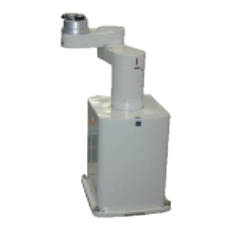
2 Robot arm 2.3 Names of each part of the robot J2-axis J4-axis - + - + J1-axis - + Mechanical interface No.2 arm + No.1 arm J3(Z)-axis - Base Fig.2-4 : Names of each part of the robot Names of each part of the robot 2-9... -
Page 20: Outside Dimensions ・ Operating Range Diagram
2 Robot arm 2.4 Outside dimensions ・ Operating range diagram (1) Outside dimensions diagram for RH-15UHC-SA 6.3a Fig.2-5 : Outside dimensions diagram for RH-15UHC-SA 2-10 Outside dimensions ・ Operating range diagram... -
Page 21: Operating Range Diagram For Rh-15Uhc-Sa
2 Robot arm (2) Operating range diagram for RH-15UHC-SA Fig.2-6 : Operating range diagram for RH-15UHC-SA Outside dimensions ・ Operating range diagram 2-11... -
Page 22: Mechanical Interface And Installation Surface
2 Robot arm (3) Mechanical interface and Installation surface Note) In order to manufacture a hand for the customer, maintain the mechanical interface section's cable outlet section. 675 (Z=0) from the robot's 8-M5 screw through hole installation surface Cable outlet section 1.6a 【Hand of mechanical interface section 】... -
Page 23: Tooling
2 Robot arm 2.5 Tooling 2.5.1 Wiring and piping for hand Shows the wiring and piping configuration for a standard-equipped hand. Terminal block for hand input Wiring for hand input Pneumatic piping (including spare) Hand output connector (for driving solenoid Machine cable connector valves, etc.) (Signals) -
Page 24: Internal Air Piping
2 Robot arm 2.5.2 Internal air piping (1) Piping is composed of 2 urethane hoses, Φ 4 X 2.5, from the intake opening of base section to the mechanical interface section. (For the spare, there is one hose base section Φ 6, mechanical interface section Φ... - Page 25 2 Robot arm Insaide the robot arm RTK-10M-8P (Wiring for hand sensor) Applicable crimp Hnad input1 (Bit 900) terminal is Hnad input2 (Bit 901) VO. 5-3. Hnad input3 (Bit 902) Robot +24V +24V Controller +24V 0V(COM) 0V(COM) 0V(COM) RTK-10M-8P Applicable crimp Hnad input4 (Bit 903) terminal is Hnad input5 (Bit 904)
-
Page 26: Electrical Specifications Of Hand Input/Output
2 Robot arm 2.5.5 Electrical specifications of hand input/output Table 2-4 : Electrical specifications of input circuit Item Specifications Internal circuit Type DC input * HCn = HC1 ~ 8 No. of input points 7(One out of seven points is dedicated) Insulation method Photo-coupler insulation Rated input voltage... -
Page 27: Air Supply Circuit Example For The Hand
2 Robot arm 2.5.6 Air supply circuit example for the hand Fig. 2-10 shows an example of pneumatic supply circuitry for the hand. (1) Place diodes parallel to the solenoid coil. (2) When the factory pneumatic pressure drops, as a result of the hand clamp strength weakening, there can be damage to the work. -
Page 28: Shipping Special Specifications, Options, And Maintenance Parts
2 Robot arm 2.6 Shipping special specifications, options, and maintenance parts 2.6.1 Shipping special specifications ■ What are Sipping special specifications? Shipping special specifications are changed at the time of shipment from the factory. Consequently, customer need to confirm the delivery date. To make changes to the specifications after shipment, service work must be performed at the work site or the robot must be returned for service. -
Page 29: Machine Cable Extension
2 Robot arm (1) Machine cable extension ■ Order type : ● Fixed type(10m) 1A-10CBL-1 ● Fixed type(15m) 1A-15CBL-1 ● Flexed type(5m) 1A-05LCBL-1 ● Flexed type(10m) 1A-10LCBL-1 ● Flexed type(15m) 1A-15LCBL-1 ■ Outline This cable is exchanged with the standard machine cable (5m) accessory to extend the distance between the controller and the robot arm. - Page 30 2 Robot arm ■ Cable configuration The configuration of the flexible cable is shown in Table 2-8. Refer to this table when selecting the cable bare. Table 2-8 : Cable configuration Item Motor signal cable Motor power cable Model 1E- □□ LCBL(S)-N 1A- □□...
-
Page 31: Options
2 Robot arm 2.7 Options ■ What are options? There are a variety of options for the robot designed to make the setting up process easier for customer needs. customer installation is required for the options. Options come in two types: "set options" and "single options". 1. -
Page 32: Maintenance Parts
Table 2-9. Purchase these parts from the designated maker or dealer when required. Some Mitsubishi-designated parts differ from the maker's standard parts. Thus, confirm the part name, robot arm and controller serial No. and purchase the parts from the dealer. -
Page 33: Controller
3Controller 3 Controller 3.1 Standard specifications 3.1.1 Standard specifications Table 3-1 : Standard specifications of controller Item Unit Specification Remarks Type CR1-571 Number of control axis Simultaneously 4(Maximum) 64 bit RISC, and DSP Memory Programmed positions and No. point 2,500 capacity of steps step... -
Page 34: Protection Specifications And Operating Supply
3Controller 3.1.2 Protection specifications and operating supply A protection method complying with the IEC Standard IP20 (Opened type) is adopted for the controller. IEC's IP symbols refer only to the degree of protection between the solid and the fluids, and don't indicated that any special protection has been constructed for the prevention against oil and water. -
Page 35: Front Operation Panel
3Controller 3.2 Names of each part <Front> <Front side of operation panel> 7) 4) EMG.STOP STATUS NUMBER CHANG DISP DOWN MODE SVO ON START RESET TEACH AUTO AUTO REMOVE T/B (Op.) (Ext.) SVO OFF STOP Front operation panel 13) 3) Fig.3-1 :... - Page 36 3Controller Fig.3-2 : Names of each controller part (Rear side) (1) Machine cable connector (for motor power ) ..Connects to the robot arm base. (CN1 connector) (2) Machine cable connector (for motor signals)..Connects to the robot arm base. (CN2 connector) (3)Power supply terminals.
-
Page 37: Outside Dimensions/Installation Dimensions
3Controller 3.3 Outside dimensions/Installation dimensions 3.3.1 Outside dimensions EMG.STOP STATUS NUMBER CHANG DISP DOWN MODE SVO ON START RESET TEACH AUTO AUTO REMOVE T/B (Op.) (Ext.) SVO OFF STOP (31) (31) (2.5) (2.5) Outside dimensions/Installation dimensions 3-27... -
Page 38: Installation Dimensions
3Controller 3.3.2 Installation dimensions EMG.STOP STATUS NUMBER CHANG DISP DOWN MODE SVO ON START RESET TEACH AUTO AUTO REMOVE T/B (Op.) (Ext.) SVO OFF STOP 170 or more Fig.3-3 : Installation of controller 3-28 Outside dimensions/Installation dimensions... -
Page 39: External Input/Output
3Controller 3.4 External input/output 3.4.1 Types (1) Dedicated input/output.......These inputs and outputs carry out the robot remote operation and status display. (2) General-purpose input/output....These are inputs and outputs that the customer can program for peripheral device control. (3) Hand input/output .........These are inputs and outputs related to the hand that the customer can program. -
Page 40: Dedicated Input/Output
3Controller 3.5 Dedicated input/output Show the main function of dedicated input/output in the Table 3-2. Refer to attached instruction manual "CR1/ CR2/CR4/CR7/CR8 Controller Detailed explanations of functions and operations" in the product for the other functions . Each parameter indicated with the parameter name is used by designated the signal No., assigned in the order of input signal No. - Page 41 3Controller Input Output Parameter Note1) name Name Function Level Name Function IODATA Numeric value input Used to designate the program No., Used to output the program No., over- Numeric value output L Note2) (start No., end No.) override value., mechanism value. ride value., mechanism No.
-
Page 42: Emergency Stop Input/Output
3Controller 3.6 Emergency stop input/output This signal is input from the "emergency stop input" terminal in the controller. Table 3-3 : Dedicated input terminals in controller Class Name Details Input Emergency stop Applies the emergency stop (Single emergency line.) Input Door switch The servo turns OFF. -
Page 43: Door Switch Function
3Controller 3.6.2 Door switch function This function retrieves the status of the switch installed on the door of the safety fence, etc., and stops the robot when the door is opened. This differs from an emergency stop in that the servo turns OFF when the door is opened and an error does not occur. -
Page 44: Parallel Input/Output Unit
3Controller 3.7 Parallel input/output unit ・ A parallel input/output card is mounted as a standard in the controller's control unit. ・ The external input/output circuit specifications are shown in Table 3-4 Table 3-5. ・ The correspondence of the external input/output connector pin No. and the colors of the connected "external input/output cable"... - Page 45 External power supply Fig.3-6 : Connection with a Mitsubishi PLC (Example of sink type) *The input/output circuit external power supply (24 VDC) must be prepared by the customer. Table 3-6 : Standard parallel I/O interface CN100pin No. and signal assignment list (2A-CBL □□...
-
Page 46: Connector Pin Layout
3Controller ・ The signals assigned as dedicated inputs can be used as general-purpose inputs during program execution. Note that for safety proposes, these should not be shared with the general-purpose inputs other than for numeric value inputs. The signals assigned as dedicated outputs cannot be used in the program. An alarm will occur during operation if used. -
Page 47: Options
3Controller 3.8 Options ■ What are options? There are a variety of options for the robot designed to make the setting up process easier for user needs. User installation is required for the options. Options come in two types: "set options" and "single options". 1.... -
Page 48: Teaching Pendant (T/B)
In ISO/10218 (1992) and JIS-B8433 (1993), this is defined as an "enable device". These standards specify that the robot operation using the teaching pendant is enabled only when the "enable device" is at a specified position. With the Mitsubishi Electric industrial robot, the above "enable device" is configured of an "Enable/Disable switch" and "Deadman switch". - Page 49 3Controller Hand strap Contrast adjusting switch Enable/Disable switch Display LCD DISABLE ENABLE R28TB TOOL JOINT MENU STOP =*/ ( )? $" : # % ! SVO ON EMG.STOP STEP - + MOVE (J1) (J1) Emergency stop - + + ↑ FORWD (J2) (J2)
- Page 50 3Controller ■ Key layout and main functions DISABLE DISABLE DISABLE DISABLE ENABLE ENABLE ENABLE ENABLE R28TB R28TB R28TB R28TB TOOL TOOL TOOL TOOL JOINT JOINT JOINT JOINT MENU MENU MENU MENU STOP STOP Back STOP STOP = = = = * *...
-
Page 51: Pneumatic Hand Interface
3Controller (2) Pneumatic hand interface ■ Order type: 2A-RZ365 ■ Outline This interface is required to use the robot arm's hand output signals. ・ Up to eight hand output points can be used with this interface. ・ The seven (One out of seven points is dedicated) hand input points can be used without this interface. -
Page 52: Control Unit
3Controller ■ Installation method This is mounted on the control unit (RZ386 card) in the controller. Securely insert the pneumatic hand interface (2A-RZ365) into the CNHNDOUT/CNHND connector on the control unit. RZ386 card Control unit <RZ386> CNHND CNHND CNHNDOUT 2A-RZ365 CNHNDOUT View A Fig.3-10 :... -
Page 53: Expansion Option Box
3Controller (3) Expansion option box ■ Order type : ● CR1-EB3 ■ Outline By installing this expansion option box to the side of the CR1-571 controller, the expansion serial interface, CC-Link interface and Ethernet interface can be used. Up to three option cards can be mounted. ■... - Page 54 3Controller Installation of expansion option box Expansion option box CR1-571 controller Positioning latch Positioning latch Rear side cable outlet 299.7 (38) 87.5 (13) Installation screw Four positions Layout of expansion option box Slot1 Plates with rails Controller connection connector Slot2 (Two positions) Slot3...
-
Page 55: Parallel I/O Unit
3Controller (4) Parallel I/O unit ■ Order type: 2A-RZ361 ■ Outline This is used to expand the external inputs and outputs. ・ The connection cable is not included. Prepare the optional external input/output cable (2A-CBL05 or 2A-CBL15). ■ Configuration Table 3-13 : Configuration device Part name Type Qty. - Page 56 3Controller Table 3-15 : Electrical specifications for the output circuits Item Specification Internal circuit Type Transistor output No. of output points Insulation method Photo-coupler insulation (24/12V) Rated load voltage DC12V/DC24V Rated load voltage range DC10.2 ~ 30V(peak voltage 30VDC) Max. load current 0.1A/point (100%) Outline Leakage current at OFF...
- Page 57 3Controller ■ Installation method The expansion parallel input/output unit is installed outside of the controller. Connect with the network connec- tion cable (NETcable-1) from the RIO1 connector in the rear of the controller.(Terminator is connected at the time of shipment) RIO1 connector upside (40)
- Page 58 3Controller RIO1 connector Parallel I/O unit 1 . . . 6 Parallel I/O unit 7 Controller back side Station No. setting Station No. setting 1 . . . 6 Note) NETcable-1 cable <CN300> <CN300> <CN100> <CN100> RIO2 connector RIO1 connector RIO1 connector RIO2 connector Note)
- Page 59 3Controller ■ Parallel I/O interface (First expansion unit) Table 3-16 : Connector CN100pin No. and signal assignment list (2A-CBL □□ Function name Function name Line color Line color Dedicated/power supply, Dedicated/power supply, General-purpose General-purpose common common Orange/Red A Orange/Blue A Gray/Red A 0V:For pins 4-7 Gray/Blue A...
- Page 60 3Controller [*1] (Set channel No. to 1.) Channel No. setting LED display <CN300> Input 48 to 63 Output 48 to 63 <CN100> Input 32 to 47 Output 32 to 47 *The 2A-RZ361 has 32 input and 32 output points unit (Occupies one channel) Fig.3-15 :...
- Page 61 3Controller ■ Parallel I/O interface (Second expansion unit) Table 3-18 : Connector CN100pin No. and signal assignment list (2A-CBL □□ Function name Function name Line color Line color Dedicated/power supply, Dedicated/power supply, General-purpose General-purpose common common Orange/Red A Orange/Blue A Gray/Red A 0V:For pins 4-7 Gray/Blue A...
- Page 62 3Controller [*1] (Set channel No. to 2.) Channel No. setting LED display <CN300> Input 80 to 95 Output 80 to 95 <CN100> Input 64 to 79 Output 64 to 79 *The 2A-RZ361 has 32 input and 32 output points unit (Occupies one Channel) Fig.3-16 :...
-
Page 63: External I/O Cable
3Controller (5) External I/O cable ■ Order type: 2A-CBL □□ Note) The numbers in the boxes □□ refer to the length. (05: 5m、 15: 15m) ■ Outline This is the dedicated cable used to connect an external peripheral device to the con- nector on the parallel input/output unit. - Page 64 3Controller ■ Connections and outside dimensions The sheath of each signal cable (50 lines) is color indicated and marked with dots. Refer to the cable color speci- fications in "Table 3-22Connector pin numbers and cable colors" when making the connections. (Eg.) Pin number: color indication 1...
-
Page 65: Personal Computer Cable
3Controller (6) Personal computer cable ■ Order type: ● For PC/AT : RS-MAXY-CBL RS-AT-RCBL (For expansion option box(CR1-EB3).) ■ Outline This is the RS-232C interface cable used for connecting the controller with a personal computer. The personal computer on hand may be usable with the above interface cable. Confirm the connection specifications when placing an order. - Page 66 3Controller RS-MAXY-CBL P/C side Robot side Type:17JE-23250(D8A6) (DDK) RS-AT-RCBL P/C side Robot side Type:17JE-23250-02(D18A1) (DDK) Fig.3-19 : Personal computer cabe connector 3-56 Options...
-
Page 67: Personal Computer Support Software/Personal Computer Support Software Mini
3Controller (7) Personal computer support software/Personal computer support software mini ■ Order type : ● Personal computer support software *For windows CD-ROM : 3A-01C-WINE ● Personal computer support software mini *For windows CD-ROM : 3A-02C-WINE ■ Outline This is handy software that fully uses the personal computer functions. It can be used in various stages from the robot specifications study (tact study, etc.) to the design support (creation and editing of programs), start up support (execution, control and debugging of program), and maintenance (remote maintenance.) - Page 68 3Controller ■ Functions Table 3-25 : Functions Note1) Function Details Functional existence Compatible model ○ ○ Personal computer running Microsoft Windows 95/98/NT 4.0 Program editing Editing functions ・ MELFA BASIC IV language compatible functions ・ Multiple editing screen simultaneously display ・...
-
Page 69: Maintenance Parts
Table 3-26. Purchase these parts from your dealer when required. Some Mitsubishi-designated parts differ from the maker's standard parts. Thus, confirm the part name, robot arm and controller serial No. and purchase the parts from your dealer. Table 3-26 : Contloller consumable parts list... -
Page 70: Software
4Software 4 Software 4.1 List of commands commands (1) MELFA-BASIC Ⅳ Table 4-1 : List of MELFA-BASIC IV commands Type Class Function Input format (example) Joint interpolation Moves to the designated position with joint interpolation. MOV P1 Linear interpolation Moves to the designated position with linear interpolation. MVS P1 Circular interpola- Moves along a designated arc (start point →... - Page 71 4Software Type Class Function Input format (example) Branching Executes program block corresponding to the designated expression value.. SELECT CASE 1 CASE 2 END SELECT Moves the program process to the next line. SKIP Subroutine Executes the designated subroutine. (Within program) GOSUB 200 Returns from the subroutine.
-
Page 72: List Of Parameters
4Software 4.2 List of parameters (1) List of parameters show the main parameter in the Table 4-2. Table 4-2 : List of parameters Parameter Details Standard tool coordinates. MEXTL Set the default value for the tool data. Unit: mm or deg. Standard base coordinates MEXBS Set the relation of the world coordinate system and robot coordinate system. -
Page 73: Change The Display Language / 表示言語の切 り 替え
4Software Parameter Details Stop input B contact desig- Change the dedicated input (stop) between the A contact and B contact. nation User-designated origin USERORG Designate the user-designated origin position. Program selection memory SLOTON Select the program selected previously when initializing the slot. The non-selected state will be entered when not set. - Page 74 4Software (2) Change the display language / 表示言語の切 り 替え The language to display on the LCD display of teaching pendant can be changed by "the display language parameter". (Japanese or English) Show the details of the parameter in the Table 4-2.
-
Page 75: Safety
5Safety 5 Safety 5.1 Safety Measures to be taken regarding safety of the industrial robot are specified in the "Labor Safety and Sanitation Rules". Always follow these rules when using the robot to ensure safety. 5.1.1 Self-diagnosis stop functions This robot has the self-diagnosis stop functions shown in Table 5-1 and the stop functions shown in Table 5-2... -
Page 76: Precautions For Using Robot
5Safety 5.1.3 Precautions for using robot The safety measures for using the robot are specified in the "Labor Safety and Sanitation Rules". An outline of the rules is given below. (1) Robot installation ・ Secure sufficient work space required to safely perform work such as teaching and maintenance related to the robot. -
Page 77: Examples Of Safety Measures
5Safety 5.1.7 Examples of safety measures Emergency stop input circuits are prepared on the user wiring terminal block of the controller. Create a circuit as shown below for safety measures <Customer-prepared wiring> <Robot controller system> + To servo main circuit power External emergency stop input S/W-EMG... -
Page 78: Working Environment
5Safety 5.2 Working environment Avoid installation in the following places as the equipment's life and operation will be affected by the ambient environment conditions. When using in the following conditions, the customer must pay special attention to the preventive measures. (1) Power supply ・... -
Page 79: 6Appendix
6Appendix 6 Appendix Appendix 1 : Specifications discussion material ■ Customer information Company name Name Address Telephone ■ Purchased mode Specification Type Standard specification RH-15UHC-SA ■ Shipping special specifications (Settings can be made only at time of shipment) Item Standard specifications Special shipping specifications Robot arm Machine cable... - Page 83 HEAD OFFICE : MITSUBISHI DENKI BLDG MARUNOUCHI TOKYO 100-8310 TELEX : J24532 CAB LE MELCO TOKYO NAGOYA WORKS : 1-14, YADA-MINAMI 5, HIGASHI-KU, NAGOYA, JAPAN JUL..2002 MEE Printed in Japan on recycled paper. Specifications are subject to change without notice.
Need help?
Do you have a question about the MELFA RH-15UHC-SA Series and is the answer not in the manual?
Questions and answers