HBM QuantumX Operating Manual
Rugged daq
Hide thumbs
Also See for QuantumX:
- Quick start manual (200 pages) ,
- Operating manual (192 pages) ,
- Operating manual (152 pages)
Table of Contents
Advertisement
Quick Links
Advertisement
Table of Contents

Related Manuals for HBM QuantumX


Summary of Contents for HBM QuantumX
- Page 1 Operating manual Rugged DAQ A3609-1.0 en...
-
Page 3: Table Of Contents
..............Connecting individual QuantumX modules with Rugged DAQ design . - Page 4 ..............QuantumX Rugged DAQ...
-
Page 5: Safety Instructions
10 V ... 30 V (DC). The supply connection, as well as the signal and sensor leads, must be installed in such a way that electromagnetic interference does not adversely affect device functionality (HBM recommendation: “Greenline shielding design”, downloadable from the Internet at http://www.hbm.com/Greenline). - Page 6 In particular, any repair or soldering work on motherboards (replacement of components) is prohibited. When exchanging complete modules, use only original parts from HBM. The module is delivered from the factory with a fixed hardware and software configuration.
- Page 7 It is also essential to comply with the legal and safety requirements for the application concerned during use. The same applies to the use of accessories. NOTE The safety instructions described here also apply to the power pack NTX002. QuantumX Rugged DAQ...
- Page 8 Components marked with this symbol can be damaged beyond repair by electrostatic discharge. Please observe the handling instructions for components exposed to the risk of electrostatic discharge. On the device Symbol: Meaning: Take details in the operating manual into account QuantumX Rugged DAQ...
- Page 9 If you need more information about waste disposal, please contact your local authorities or the dealer from whom you purchased the product. QuantumX Rugged DAQ...
- Page 10 − Before cleaning, disconnect the module from all connections. − Clean the housing with a soft, slightly damp cloth. Never use solvent as this could damage the labeling or the housing. − Do not use high-pressure cleaners for cleaning. QuantumX Rugged DAQ...
-
Page 11: Introduction
These documents can be found • On the QuantumX system CD supplied with the device S After installation of the QuantumX Assistant on the hard drive of your PC S Up-to-date versions are always available from our Internet site at http://www.hbm.com/hbmdoc... -
Page 12: The Quantumx Rugged Daq Series
Introduction The QuantumX Rugged DAQ series The QuantumX Rugged DAQ series is a modular and universally applicable measurement system. The modules can be individually combined and intelligently connected according to the measurement task. The distributed operation makes it possible to position individual modules close to the measuring points, resulting in short sensor lines. - Page 13 Configurable active digital filter (Bessel, Butterworth) Configurable scaling (can also be saved in TEDS) Sensors assigned using the sensor database can be calibrated via the channel and written back into the sensor database. TEDS = Transducer Electronic Data Sheet QuantumX Rugged DAQ...
-
Page 14: Digitalization And Signal Path
Each QuantumX measurement channel generates two signals. These signals can be individually parameterized with a different data rate and filter. Parameterization is easiest to implement with the “QuantumX Assistant” software (Signal tab). If several modules are connected together via the FireWire bus, signals can be sent in real time (isochronous), e.g. -
Page 15: Quantumx Rugged Daq Module Synchronization
Master must be used for synchronization. This is also a requirement if the QuantumX modules are a long distance away from one another and a FireWire connection would be too complex. - Page 16 Introduction Synchronization via an NTP server Each QuantumX module can synchronize its internal clock with an NTP server. The NTP time is distributed to the other modules via FireWire. It is possible to achieve accuracies in the 100 μs range, although this depends on the relevant Ethernet utilization.
- Page 17 Introduction Synchronization via IRIG-B IRIG-B is a standardized time coding. To time-synchronize the QuantumX system, the digital or analog modulated time signal is sent externally to any analog voltage input of the amplifier type MX840A-P (see assignment, Chapter 6.2.1). The B127 format uses an analog modulation. Connection is identical to that of a 10 V voltage sensor.
- Page 18 These time stamps are appended to the measured values. You can choose from several synchronization methods: S Synchronizing via FireWire S Synchronizing via EtherCAT (CX27) S Synchronizing via NTP (Network Time Protocol) with FireWire S Synchronizing via NTP without FireWire QuantumX Rugged DAQ...
-
Page 19: Software
Software Software The supplied QuantumX System CD contains a powerful software package consisting of the QuantumX Assistant, programming libraries for .NET/COM, TEDS Editor, FireWire driver and ® a program for module firmware updating. The software product catman EASY is available as an independent product package. -
Page 20: Catman®Ap
AutoSequence automates repeating measurement or analysis steps EasyPlan enables preparatory parameterization and configuration without amplifier connection EasyScript is based on current VBA standard (Visual Basic for Applications) and enables writing of own scripts for individual measurement tasks QuantumX Rugged DAQ... -
Page 21: Programming Interface (Api)
Programmers can directly access functions of other programs via APIs and use these in their own programs. With the API, you have full access to all QuantumX functions through an individually programmed application, e.g. your own operator interface. - Page 22 Software • Compare your version with the actual firmware version on the Internet under: www.hbm.comquantumX QuantumX Rugged DAQ...
- Page 23 UpdateDownload) • Download the actual software package from the HBM website • Close all open HBM software, install the new software and start the “QuantumX Firmware Update” program • Click on the “Find modules” symbol or press the function key F4 •...
-
Page 24: Teds Editor
The HBM TEDS Editor can read, edit and write TEDS data directly via a measurement channel or via the HBM TEDS dongle. If TEDS is retrofitted, the Editor will provide the corresponding templates for various transducer types. Some templates can be stored and loaded. -
Page 25: Housing
These indicate which degree of protection a housing offers against contact or foreign bodies (first digit) and moisture (second digit). The QuantumX Rugged DAQ modules are available in housings with degree of protection IP67 (as per DIN EN 60529). -
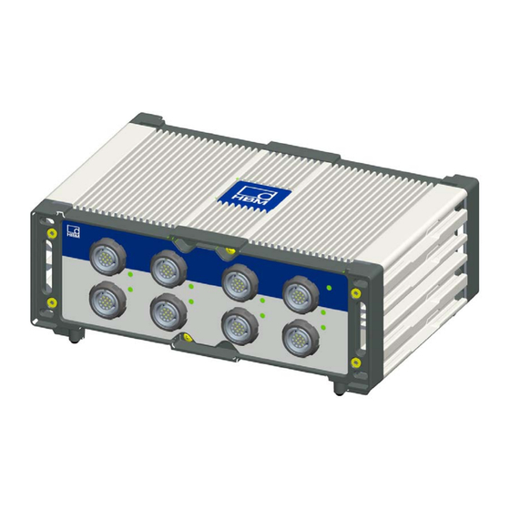
Page 26: Connecting Individual Quantumx Modules With Rugged Daq Design
Connection Connecting individual QuantumX modules with Rugged DAQ design Connecting the supply voltage Connect the modules to a DC voltage of 10 V ... 30 V (24V recommended). The power consumption per device can be found in the following table. -
Page 27: Modules And Transducers
(or shielding) are designed to be physically separate in the HBM devices. The mains earth connector or a separate earth potential lead should serve as the earth connection as is the case for example regarding potential compensation in buildings. -
Page 28: Active Transducer Connection
Check the correct voltage setting when connecting a sensor. Too high a voltage can destroy the sensor. The voltage value is a part of the MX840 parameterization and can only be changed with a new parameterization. The sensor supply is switched off in the delivery condition. QuantumX Rugged DAQ... -
Page 29: Teds
Transducer manufacturer, type, serial number, etc. Calibration date, recalibration interval, calibrator’s initials, etc. The amplifiers in the QuantumX series are capable of reading the transducer information stored in the data sheet and automatically converting it into amplifier settings to enable rapid and safe measurement operation. - Page 30 TEDS in the transducer connector. Amplifiers with direct connection of IEPE transducers support TEDS Version 1.0. A special TEDS module is integrated in some HBM transducers, this can transmit the TEDS data via the feedback line of a sensor (patented “zero-wire circuit”).
- Page 31 The following figure shows the retrofitting of TEDS in a plug. HBM recommends the TEDS module (1-wire EEPROM) DS24B33 from Dallas Maxim. Minimum requirements to read and write this chip are firmware version 1.21.16 / 2.21.16 and TEDS Editor version 3.3.
-
Page 32: Autocalibration / Autoadjustment
This allows the modules to achieve a high stability without having to cyclically freeze the measured value. Autoadjustment is switched on the default settings. The cyclical calibration can be briefly ® deactivated via the QuantumX Assistants and via catmanEASY QuantumX Rugged DAQ... -
Page 33: Mx840A-P Universal Amplifier
1 ... 8 Current-fed piezoelectric transducer 1 ... 8 ® (IEPE, Piezoresistive transducer 1 ... 8 Ohmic resistor 1 ... 8 Potentiometer 1 ... 8 Resistance thermometers PT100, PT1000 1 ... 8 Incremental encoder 5 ... 8 from 64 QuantumX Rugged DAQ... - Page 34 Connection Connectable MX840A-P transducers (continued) Transducer type Connection sockets See Page SSI protocol 5 ... 8 Frequency measurement, pulse counting 5 ... 8 from 64 Torque/speed 5 ... 8 65, 66 CANbus QuantumX Rugged DAQ...
-
Page 35: Mx840A-P Pin Assignment
Active sensor supply 5 ... 24 V (0 V) Active sensor supply 5 ... 24 V (+) Sense lead (−), f (−)-signal differential, CAN-High, SSI clock (−) Sense lead (+), f (+)-signal differential, CAN-Low, SSI clock (+) TEDS (−), ground frequency measurement TEDS (+) QuantumX Rugged DAQ... -
Page 36: Mx840A-P Status Display
CANbus in “WARNING” state, CAN data received but bus is occasionally disturbed; buffer overflow, individual data lost CANbus in “ERROR” or “BUS-OFF” state, CAN data cannot be received or processed General rule: Brief flashing → TEDS identified (green: is used, orange: is not used). QuantumX Rugged DAQ... -
Page 37: Mx411-P Highly Dynamic Universal Amplifier
1 ... 4 Inductive half bridge 1 ... 4 SG half bridge 1 ... 4 Voltage 1 ... 4 58, 59 Current 1 ... 4 Current-fed piezoelectric transducer 1 ... 4 ® (IEPE, Piezoresistive transducer 1 ... 4 QuantumX Rugged DAQ... -
Page 38: Mx411-P Pin Assignment
Signal ground Always connect with Pin 4! (Plug-in detection) Current input "20 mA (+) Measurement signal (+) Measurement signal (−) Active sensor supply (−) Active sensor supply (+) Sense lead (−) Sense lead (+) TEDS (−) TEDS (+) QuantumX Rugged DAQ... -
Page 39: Mx411-P Status Display
Flashing orange (5s), then green Manual configuration ongoing (ignore TEDS) No sensor connected Channel error (incorrectly parameterized, connection error, invalid TEDS data) Overload of sensor supply General rule: Brief flashing → TEDS identified (green: is used, orange: is not used). QuantumX Rugged DAQ... -
Page 40: Mx460-P Frequency Measuring Amplifier
1 ... 4 65, 66 Frequency measurement, pulse counting 1 ... 4 from 64 Pulse width, pulse duration, period duration 1 ... 4 (PWM) Passive inductive encoder 1 ... 4 Incremental encoder 1 ... 4 from 64 QuantumX Rugged DAQ... -
Page 41: Mx460-P Pin Assignment
No function Frequency input f (−) Frequency input f Active sensor supply 5 ... 24 V (−) Active sensor supply 5 ... 24 V (+) Frequency input f (−) Frequency input f TEDS (−), signal ground TEDS (+) QuantumX Rugged DAQ... -
Page 42: Mx460-P Status Display
TEDS data being read in Flashing orange (5s), then green Manual configuration ongoing (ignore TEDS) No sensor connected Channel error (incorrectly parameterized, connection error, invalid TEDS data) General rule: Brief flashing → TEDS identified (green: is used, orange: is not used). QuantumX Rugged DAQ... -
Page 43: Mx1609-P Thermocouple Amplifier
Connectable MX1609-P transducers Transducer type Connection sockets Thermocouple type K 1 ... 16 MX1609-P Thermal element − − Type Thermocouple material 1 (+) Thermocouple material 2 (−) Nickel-chrome (color code green) Nickel-aluminum (color code white) QuantumX Rugged DAQ... -
Page 44: Thermocouple With Teds Functionality (Rfid)
(°C or °K). The data are input with the TEDS Editor provided by HBM. They are then written onto the RFID chip via a corresponding RFID transponder in the amplifier. -
Page 45: Mx1609-P Status Display
Error-free operation (“Use TEDS” or “if available” set green and TEDS data valid) No sensor connected Channel error (incorrectly parameterized, connection error, invalid TEDS data) Overload of sensor supply General rule: Brief flashing → TEDS identified (green: is used, orange: is not used). QuantumX Rugged DAQ... -
Page 46: Mx1601-P Amplifier
Connectable MX1601-P transducers Transducer type Connection sockets See Page Voltage 1 ... 16 58, 59 Current 1 ... 16 Current-fed piezoelectric transducer 1 ... 16 ® (IEPE, QuantumX Rugged DAQ... -
Page 47: Mx1601-P Pin Assignment
1 ... 8. Channels 9 ... 16 output the supply voltage (10 ... 30 V) minus approx. 1 V. A current of max. 30 mA can be consumed, the current limitation switches the transducer excitation off if current consumption is higher. QuantumX Rugged DAQ... -
Page 48: Transducer Connection
Excitation (+) blue Measurement signal (−) yellow Cable shield Hsg. green Sense lead (+) gray Sense lead (−) 1 Ground 2 Data 1 2 3 3 No function 1-wire EEPROM (optional) Hsg. = housing view from below QuantumX Rugged DAQ... -
Page 49: Full Bridge, Inductive
Excitation (+) blue Measurement signal (−) yellow Cable shield Hsg. green Sense lead (+) gray Sense lead (−) 1 Ground 2 Data 3 No function 1 2 3 1-wire EEPROM (optional) Hsg. = housing view from below QuantumX Rugged DAQ... -
Page 50: Full Bridge, Piezoresistive
Measurement signal (+) Excitation (−) Excitation (+) Measurement signal (−) Cable shield Hsg. Sense lead (+) Sense lead (−) 1 Ground 2 Data 1 2 3 3 No function 1-wire EEPROM (optional) view from below Hsg. = housing QuantumX Rugged DAQ... -
Page 51: Half Bridge, Sg
Excitation (−) blue Excitation (+) yellow Cable shield Hsg. green Sense lead (+) gray Sense lead (−) 1 Ground 2 Data 1 2 3 3 No function 1-wire EEPROM (optional) view from below Hsg. = housing QuantumX Rugged DAQ... -
Page 52: Half Bridge, Inductive
Excitation (−) blue Excitation (+) yellow Cable shield Hsg. green Sense lead (+) gray Sense lead (−) 1 Ground 2 Data 1 2 3 3 No function 1-wire EEPROM (optional) view from below Hsg. = housing QuantumX Rugged DAQ... -
Page 53: Potentiometric Transducer
Measurement signal (+) Excitation voltage (−) Excitation voltage (+) Cable shield Hsg. Sense lead (+) Sense lead (−) 1 Ground 2 Data 1 2 3 3 No function Hsg. = housing 1-wire EEPROM (optional) (view from below) QuantumX Rugged DAQ... -
Page 54: Lvdt Transducers
Measurement signal (+) Excitation (−) Excitation (+) Measurement signal (−) Hsg. Cable shield Sense lead (+) Sense lead (−) 1 Ground 2 Data 1 2 3 3 No function 1-wire EEPROM (optional) view from below Hsg. = housing QuantumX Rugged DAQ... -
Page 55: Current-Fed Piezoelectric Transducer
MX411-P (directly on a SubHD or via BNC adapter), MX1601-P (directly on a connector) MX840A-P with 10 V analog input and 24 V excitation via a smart module MX411-P MX1601-P IEPE (−) Cable shield Hsg. Hsg. Hsg. = housing NOTE IEPE transducers with TEDS version 1.0 are supported. QuantumX Rugged DAQ... - Page 56 IEPE with constant current (BNC socket) and 1-EICP-B-2 outputs a standardized voltage signal " 10 V 1-SAC-EXT-MF-x-2 Connection cable Cable between Smart module and SubHD plug (x = length in meters) Device connector QuantumX Rugged DAQ connector 1-CON-P1007 QuantumX Rugged DAQ...
- Page 57 TEDS data stored directly in the IEPE transducer cannot be read by the Smart module. TEDS can be retrofitted in the QuantumX Rugged DAQ connector so that the Smart module can be read in and the channel settings automated according to the IEPE transducer.
-
Page 58: Dc Voltage Sources 100 Mv
1 Ground 2 Data 1 2 3 3 No function 1-wire EEPROM (optional) view from below Hsg. = housing Adjustable sensor supply: Pin 10 Pin 7 5 V … 24 V: 0 V: Pin 9 Pin 6 QuantumX Rugged DAQ... -
Page 59: Dc Voltage Sources 10 V Or 60 V Range
5 V … 24 V: Pin 10 Pin 6 0 V: Pin 9 MX840A-P: You can select two measuring ranges (10 V or 60 V), depending on the parameterization. Incorrect parameterization will not cause the destruction of the amplifier. QuantumX Rugged DAQ... -
Page 60: Dc Current Sources 20 Ma
1 2 3 3 No function Hsg. = housing 1-wire EEPROM (optional) view from below Pin 7 Adjustable sensor supply: 5 V … 24 V: Pin 10 Pin 6 0 V: Pin 9 Maximum current "30 mA QuantumX Rugged DAQ... -
Page 61: Dc Current Sources 20 Ma − Current-Fed
Adjustable sensor supply: 5 V … 24 V: Pin 10 Pin 6 0 V: Pin 9 Maximum current "30 mA The sensor supply must be connected in series. This however terminates the electrical isolation to the module supply. QuantumX Rugged DAQ... -
Page 62: Resistance
When connecting a two-wire sensor, wire bridges must be soldered in the connector (between measurement line and supply) 1 Ground 2 Data 1 2 3 3 No function 1-wire EEPROM (optional) Hsg. = housing view from below QuantumX Rugged DAQ... -
Page 63: Resistance Thermometers Pt100, Pt1000
Pt100 / Pt1000: MX840A-P MX840A-P Four-wire circuit Excitation (−) Measurement signal (−) ϑ Cable shield Hsg. Measurement signal (+) Excitation (+) 2 Data 1 2 3 3 No function 1-wire EEPROM (optional) Hsg. = housing view from below QuantumX Rugged DAQ... -
Page 64: Frequency, Differential, Without Directional Signal
1 2 3 3 No function 1-wire EEPROM (optional) Hsg. = housing view from below Adjustable sensor supply: Pin10: 5 V ... 24 V; 0.7 W per channel, in total 2 W. Further information, see data sheet. Pin 9: QuantumX Rugged DAQ... -
Page 65: Frequency, Differential, With Directional Signal
1 2 3 3 No function 1-wire EEPROM (optional) view from below Hsg. = housing Adjustable sensor supply: Pin10: 5 V ... 24 V; 0.7 W per channel, in total 2 W. Further information, see data sheet. Pin 9: QuantumX Rugged DAQ... -
Page 66: Frequency, Single-Pole, Without Directional Signal
Plug 1 white Cable shield Hsg. green Ground 1 Ground 2 Data 1 2 3 3 No function 1-wire EEPROM (optional) view from below Hsg. = housing Adjustable sensor supply: Pin10: 5 V ... 24 V Pin 9: QuantumX Rugged DAQ... -
Page 67: Frequency, Single-Pole, With Directional Signal
Industrial pulse Cable shield encoder Hsg. Ground 1 Ground 2 Data 1 2 3 3 No function 1-wire EEPROM (optional) view from below Hsg. = housing Adjustable sensor supply: Pin10: 5 V ... 24 V Pin 9: QuantumX Rugged DAQ... -
Page 68: Encoder And Pulse Encoder, Differential
Cable shield Hsg. encoder (−) Ground 1 Ground 2 Data 1 2 3 3 No function 1-wire EEPROM (optional) view from below Hsg. = housing Adjustable sensor supply: Pin10: 5 V ... 24 V Pin 9: QuantumX Rugged DAQ... -
Page 69: Encoder And Pulse Encoder, Single-Pole
Cable shield Hsg. encoder Zeroing pulse + Ground 1 Ground 2 Data 1 2 3 3 No function 1-wire EEPROM (optional) Hsg. = housing view from below Adjustable sensor supply: Pin10: 5 V ... 24 V Pin 9: QuantumX Rugged DAQ... -
Page 70: Ssi Protocol
Ground = Data (−) 1 (−) = Data (+) 1 (+) = Shift clock (−) 2 (−) = Shift clock (+) 2 (+) Hsg. = housing Adjustable sensor supply: Pin10: 5 V ... 24 V Pin 9: QuantumX Rugged DAQ... -
Page 71: Passive Inductive Encoder
Supported by the MX460-P module. MX460-P Maximum input voltage to housing and supply ground: "60 V Cable shield Hsg. Ground 1 Ground 2 Data 1 2 3 3 No function 1-wire EEPROM (optional) Hsg. = housing view from below QuantumX Rugged DAQ... -
Page 72: Pwm − Pulse Width, Pulse Duration, Period Duration
PWM − Pulse width, pulse duration, period duration Supported by the following modules: MX460-P MX460-P (−) Transducers Cable shield Hsg. Ground 2 Data 1 2 3 3 No function Hsg. = housing Adjustable sensor supply: Pin10: 5 V ... 24 V Pin 9: QuantumX Rugged DAQ... -
Page 73: Pwm − Pulse Width, Pulse Duration, Period Duration, Single-Pole
Supported by the following modules: MX460-P MX460-P Cable shield Hsg. Transducers Ground 1 Ground 2 Data 1 2 3 3 No function Hsg. = housing Adjustable sensor supply: Pin10: 5 V ... 24 V Pin 9: QuantumX Rugged DAQ... -
Page 74: Canbus
CAN messages can be acquired with the following modules: Channel 1 from MX840A-P. CAN messages can be acquired and sent with the following modules: MX840A-P (only module-internal measured quantities). A dbc data file can be generated using the QuantumX assistant. -
Page 75: Faq
“ "The device scan cannot find any connected devices. … What might be causing this, how can I set up a connection to QuantumX Rugged DAQ ? Reply/Solution: First of all, check carefully whether the network address of the QuantumX Rugged DAQ amplifier is in the same subnet as the PC and whether this IP address is correctly entered in the scan options of catman®Easy/AP. - Page 76 General reasons S Is the QuantumX Rugged DAQ module switched on and is the module LED lit up green? S Is the interface cable connected? S Have you activated the correct interface or correct interface adapter?
- Page 77 S If you want to use the QuantumX Rugged DAQ module in a larger network, please contact your network administrator. There are a series of options in administrated networks to limit or completely prevent data transmission between individual subscribers.
-
Page 78: Accessories
FireWire cable connector between QuantumX Rugged DAQ modules 1-KAB272-0.2 (lengths: 0.2m/2 m/5 m); Fitted both ends with appropriate plugs. 1-KAB272-2 Note: The cable can be used to optionally supply connected QuantumX 1-KAB272-5 Rugged DAQ modules with voltage (max. 1.5 A, from source to last acceptor) - Page 79 Bundle, comprising 10 x mini thermocouple plugs with integrated RFID 1-THERMO-MINI RFID for thermocouples type K chip for measuring point detection for the MX1609-P thermocouple measuring amplifier of the QuantumX family; type K: NiCr-NiAl, RFID integrated, green, male Accessories for the connection of the Smart modules Article Description Order no.
-
Page 80: System Accessories
Accessories System accessories Voltage supply 8.2.1 Power pack NTX002 Europe mains cable NTX002 Mains Modules UK mains cable USA mains cable Australia mains cable Order No.: 1-NTX002 QuantumX Rugged DAQ... -
Page 81: Firewire
Accessories FireWire 8.3.1 FireWire cable (module to module; IP68) 0.2 m 2.0 m 5.0 m ODU plug 1-KAB272-2 (Length 2 m) Order No.: 1-KAB272-0.2 (Length 0.2 m) 1-KAB272-5 (Length 5 m) QuantumX Rugged DAQ... -
Page 82: Connection Cable
Accessories 8.3.2 Connection cable FireWire B plug Female connector Order number: 1-KAB293-5 (Length 5 m) 1-KAB276-3 (Length 3 m, like KAB293-5 but with attached voltage supply cable) QuantumX Rugged DAQ... -
Page 83: Mx1609-P Accessories
Accessories MX1609-P accessories 8.4.1 Thermo-connector with integrated RFID chip RFID Connectors for thermocouple amplifiers: MX1601-P: Type K Package unit: 10 mini connectors for thermocouples type K Order number: 1-THERMO-MINI QuantumX Rugged DAQ... -
Page 84: Support
Tel. +49 6151 8030, Fax +49 6151 8039 100 E-mail: info@hbm.com www.hbm.com North and South America HBM, Inc., 19 Bartlett Street, Marlborough, MA 01752, USA Tel. +1 800 578 4260 / +1 508 624 4500, Fax +1 508 485 7480 E-mail: info@usa.hbm.com Asia Hottinger Baldwin Measurement (Suzhou) Co., Ltd. - Page 85 Support QuantumX Rugged DAQ...
- Page 86 Support QuantumX Rugged DAQ...
- Page 88 Hottinger Baldwin Messtechnik GmbH Im Tiefen See 45 S 64293 Darmstadt S Germany Tel. +49 6151 803-0 S Fax: +49 6151 803-9100 Email: info@hbm.com S www.hbm.com...
Need help?
Do you have a question about the QuantumX and is the answer not in the manual?
Questions and answers