Table of Contents
Advertisement
Quick Links
Advertisement
Table of Contents

Subscribe to Our Youtube Channel
Related Manuals for HBM GEN3i


Summary of Contents for HBM GEN3i
- Page 1 User Manual English Portable Data Recorder GEN3i...
- Page 2 GEN3i Document version 3.1 - December 2016 References made to the Perception software are for version 6.72 or higher www.hbm.com/terms For HBM's Terms and Conditions visit HBM GmbH Im Tiefen See 45 64293 Darmstadt Germany Tel: +49 6151 80 30 Fax: +49 6151 8039100 Email: info@hbm.com...
- Page 3 For information about LICENSE AGREEMENT AND WARRANTY refer to www.hbm.com/terms. Trademarks and patents ® StatStream is a registered trademark of HBM in the European Union and a trademark in other countries. ® StatStream is patented in the US, Patent No. 7,868,886; patent pending in other countries.
- Page 4 I3763-3.1 en HBM: public...
-
Page 5: Table Of Contents
Electro-Magnetic Compatibility (EMC) Environment 3.2.1 WEEE - Waste Electrical and Electronic Equipment 3.2.1.1 Packaging 3.2.1.2 Environmental protection CE Declaration of conformity FCC Class A Notice Batteries General Removal and replacement 4.2.1 Remove/replace the battery from the backplane I3763-3.1 en HBM: public... - Page 6 Signal conditioning Data storage PC Section Perception Software 6.8.1 Windows logon password and remote desktop access Perception language settings Setting up the GEN3i PC connections 7.1.1 USB 3.0 and USB 2.0 ports 7.1.2 DVI-I Graphics and display ports 7.1.3 Sound, microphone, speakers Removing and installing input cards 7.2.1...
- Page 7 Front panel control Getting started Wireless network 8.3.1 Windows® 7: To connect GEN3i to the local wireless network: 8.3.2 Windows® 7: To disconnect GEN3i from the local wireless network: 8.3.3 Windows® 10: To connect GEN3i to the local wireless network: 8.3.4...
- Page 8 Warnings 11.6.1.3 Installation steps 11.7 Option - IRIG and IRIG/GPS time synchronization 11.7.1 GPS Antenna System Rules 11.7.1.1 Rule 1: Antenna placement 11.7.1.2 Rule 2: Is a GPS line amplifier needed? 11.7.1.3 Rule 3: Lightning arrestors I3763-3.1 en HBM: public...
- Page 9 Understanding the GN815 and GN816 input 12.3.5.1 Characteristics per channel: 12.3.5.2 Using probes: 12.3.6 GN815 and GN816 Input overload protection 12.3.6.1 Thermal monitor of the input channels 12.3.6.2 Restore range selected by user automatically 12.3.6.3 Thermal shutdown in critical conditions I3763-3.1 en HBM: public...
- Page 10 High resolution IEPE and Charge input cards 12.8.1 GN3210 IEPE and charge 250 kS/s input card 12.8.2 GN3211 basic 20 kS/s input card 12.9 GN401 Optical Fiber Isolated 100 MS/s input card 12.10 Binary marker cards I3763-3.1 en HBM: public...
- Page 11 Switch delays 14.4 Common terms used in IEEE 1588 14.5 GEN series synchronization methods compared 14.5.1 Signal phase shift synchronization 14.5.2 Trigger synchronization 14.5.3 Absolute time of day synchronization 14.5.4 Start/Stop synchronization 14.5.5 Synchronization specification overview I3763-3.1 en HBM: public...
- Page 12 15.3.3 Probes and differential measurements 15.4 Current shunt measurements Specifications B3762–5.1 en (GEN3i Portable Data Recorder) B2629–2.1 en (GEN series GN401) B2633–2.1 en (GEN series GN410) B2639–2.1 en (GEN series GN411) B2627-2.1 en (GEN series GN412) B4160-1.1 en (GEN series GN413) B2631-2.0 en (GEN series GN440)
- Page 13 Current transducers and accessories B.8.1 Current transducers B.8.2 Connection cable LEM CT to MCTS B.8.3 Power supply for current transducer B.8.4 Current transducer (CT) wire diagram Fiber optic cables and SFPs B.9.1 Standard fiber optic duplex cable I3763-3.1 en HBM: public...
- Page 14 Passive, single-ended isolated probes B.15.3 Passive, differential matched isolated voltage probes B.15.4 Active, differential voltage probe B.15.5 High precision differential probe Maintenance Preventive maintenance Preventive drive replacement C.2.1 Hard disk drive C.2.2 Solid State Drive (SSD) I3763-3.1 en HBM: public...
- Page 15 How to change the Windows 10 display language E.7.3 Installing a Language Pack in Windows 7 Ultimate E.7.4 Installing a Language Pack in Windows 10 Upgrading GEN3i and GEN7i to Windows 10 Enable the Windows 10 upgrade on GEN3i/GEN7i E.10 Embedded Software upgrades E.10.1 Boot recovery switch E.11...
- Page 16 GEN3i/GEN7i with up to three QuantumX "B" version modules G.3.3.1 Background network details G.3.4 GEN3i/GEN7i with standard network switch and four or more of QuantumX "B" version modules G.3.5 GEN3i/GEN7i with PTP network switch and four or more of QuantumX "B" version modules G.3.6 GEN3t/GEN7tA/GEN17tA with single QuantumX "B"...
- Page 17 Triggering External Start/Stop on Digital Event/Timer/Counter connector Calculating maximum fiber cable length Wake On LAN support (WOL) H.5.1 Locating GEN3i and GEN7i MAC/Physical address H.5.2 Locating GEN3t, GEN7tA and GEN17tA MAC/Physical address Configuring an encoder with direction and reset H.6.1 From encoder to level converter H.6.2...
- Page 18 GEN DAQ optical cables - Restriction of Hazardous Substances Directive (RoHS) status 1146 GEN DAQ probes - Restriction of Hazardous Substances Directive (RoHS) status 1147 GEN DAQ current clamps - Restriction of Hazardous Substances Directive (RoHS) status 1148 I3763-3.1 en HBM: public...
-
Page 19: About This Manual
ESD if proper precautions are not taken. HINT/TIP The info icon indicates sections which provide additional information about the product. This information is not essential for correct operation of the instrument, but provides knowledge to make better use of the instrument. I3763-3.1 en HBM: public... -
Page 20: Manual Conventions
For clarity and convenience, these conventions are used throughout this manual: Menu names from the display appear in bold, blue lettering. Settings within a menu appear in bold, red lettering. Front panel controls and control names appear in bold, black lettering. I3763-3.1 en HBM: public... -
Page 21: Safety Messages
The instrument must not be operated with the covers removed. This instrument must not be used in life support roles. There are no user serviceable parts inside the instrument. I3763-3.1 en HBM: public... - Page 22 In particular, any repair or soldering work on cards (replacement of components) is prohibited. When exchanging complete units, use only original parts from HBM. The unit is delivered from the factory with a fixed hardware and/or software configuration.
- Page 23 It is essential that the legal and safety requirements for the product and any accessories are complied with during use. I3763-3.1 en HBM: public...
-
Page 24: Fcc And General
Operation of this equipment in a residential area is likely to cause interference, in which case the user at his own expense will be required to take whatever measures may be required to correct the interference. I3763-3.1 en HBM: public... -
Page 25: Grounding
The greatest source of hazardous energy in most cases is direct energizing of the equipment from a power-system or source. I3763-3.1 en HBM: public... - Page 26 GEN3i WARNING If connection to a protective ground is not possible for any reason, then please refer to the international safety standard EN 50191:2000 I3763-3.1 en HBM: public...
-
Page 27: Instrument Symbols
This symbol shows that the switch is a power switch. When pressed, the instrument state toggles between the operating and power-off mode. When the system is in power-off mode, all electronics are disconnected from the power, except for a small circuit used to detect the switch state. I3763-3.1 en HBM: public... -
Page 28: Protection And Isolation
Measurements for this category are circuit breakers, wiring, junction boxes, etc. This category expects a minimum of two levels of overcurrent protection between the transformer and connection point of the measurement. (See Figure 2.1). I3763-3.1 en HBM: public... - Page 29 5 sec at 2210 V RMS and impulse 4000 V. The maximum operating input voltage is 1000 V DC. This device is to be used to measure CAT II circuitry up to 600 V. I3763-3.1 en HBM: public...
-
Page 30: Basic Insulation Versus Reinforced
As can be seen below, basic insulation and supplementary insulation is one mean of protection, but reinforced isolation is also a means of protection. The test voltages are different for each mean of protection, as can be found in the table above. I3763-3.1 en HBM: public... -
Page 31: Additional Means Of Protection For Single Fault Conditions
3510 V RMS and impulse 6400 V. The maximum operating input voltage is 1000 V DC. This device is to be used to measure CAT II circuitry up to 600 V. I3763-3.1 en HBM: public... -
Page 32: Protection
Proper use of this device depends on careful reading of all instructions and labels. If the instrument is used in a manner not specified by HBM, the protection provided by the instrument can be impaired. WARNING This instrument must not be operated in explosive atmospheres. -
Page 33: Overvoltage/Current Protection
Even low voltage inputs may contain high voltage fast transients (spikes), which could damage the input. For this reason it is not safe, for instance, to make direct connections to an AC line supply, unless specifically stated otherwise for the specific input. I3763-3.1 en HBM: public... -
Page 34: Environment
To clean the instrument, disconnect all power sources and clean the housing with a soft, slightly damped (not wet!) cloth. It is the responsibility of the user to ensure the safety of any accessories used with the instrument, such as probes. I3763-3.1 en HBM: public... -
Page 35: Laser Safety
Human Services (DHHS) regulation CDRH 21 CFR, Chapter I Subchapter J Part 1040.10. Outside the USA, the GEN Series products are certified as a Class 1 laser product conforming to the requirements contained in IEC/EN 60825-1:1994+A1+A2 and IEC/EN 60825-2. I3763-3.1 en HBM: public... -
Page 36: Manual Handling Of Loads
Should the carrier wear gloves to get a better grip and to protect hands? Contact the “Occupational Health and Safety” organization, or equivalent, in your country for more information. The GEN3i weighs approximately 12 kg with three acquisition cards plugged in (9 kg without acquisition cards) : I3763-3.1 en HBM: public... -
Page 37: International Safety Warnings
I3763-3.1 en HBM: public... - Page 38 I3763-3.1 en HBM: public...
- Page 39 (Pätevät asentajat ovat henkilöitä, jotka erikoiskoulutuksensa, tietojensa ja kokemuksensa sekä asiaan kuuluvien määräysten tuntemuksensa ansiosta pystyvät arvioimaan heille annettuja töitä ja havaitsemaan mahdolliset vaarat ja jotka heidän työnantajansa on nimennyt ammattitaitoisiksi asentajiksi). I3763-3.1 en HBM: public...
- Page 40 été désignées comme techniciens qualifiés par leur employeur). I3763-3.1 en HBM: public...
- Page 41 Ausbildung, Kenntnisse und Erfahrungen sowie Kenntnis der einschlägigen Bestimmungen in der Lage, die ihnen anvertrauten Arbeiten zu beurteilen und mögliche Risiken zu erkennen, sowie Personen, die durch ihren Arbeitgeber zu qualifizierten Technikern ernannt worden sind). I3763-3.1 en HBM: public...
- Page 42 , preparazione ed esperienza specialistica, nonché conoscenza delle disposizioni di settore, è in grado di valutare il lavoro che gli viene assegnato e di individuare possibili rischi, oltre ad essere stato nominato tecnico qualificato dal proprio datore di lavoro). I3763-3.1 en HBM: public...
- Page 43 å gå inn i arbeidet som de har fått i oppdrag å utføre og detektere mulige farer, og som er blitt utnevnt som kvalifiserte teknikere av sin arbeidsgiver. I3763-3.1 en HBM: public...
- Page 44 à sua formação especializada, ao conhecimento e à experiência, bem como ao seu conhecimento das disposições relevantes, são capazes de avaliar o trabalho que lhes é confiado e detetar possíveis riscos e são pessoas que foram nomeadas técnicos qualificados pelo seu empregador.) I3763-3.1 en HBM: public...
- Page 45 é confiado e detectar possíveis riscos e são pessoas que foram nomeadas técnicos qualificados por seu empregador.) I3763-3.1 en HBM: public...
- Page 46 I3763-3.1 en HBM: public...
- Page 47 övervakas av en kvalificerad tekniker. (Kvalificerade tekniker är personer som på grund av sin specialistutbildning, kunskap och erfarenhet liksom sin kunskap om relevanta enheter kan utvärdera arbetet som tilldelas dem och göra kvalificerade riskbedömningar samt utses av sina arbetsgivare till kvalificerade tekniker). I3763-3.1 en HBM: public...
- Page 48 I3763-3.1 en HBM: public...
- Page 49 GEN3i 日本語 安全上の警告 本機器の操作は、電源ケーブルの保護接地線で接地(アース)を施した上で 行ってください。また、安全接地用端子が存在する場合は、これを経由して 本機器を接地してください。機器の内部または外部にある保護接地線が遮断 されると、機器が危険な状態に陥る可能性があります。故意に保護接地線を 遮断することを禁止します。また、入力信号が33V RMS、ピーク時に46.7V RMS、または70V DCを超える場合は、信号接地線を接続してください(IEC 61010-1:2010) 。 カバーは取り外さないでください。 電源ヒューズが故障により飛んだ場合、機器のAC電源スイッチが損傷するお それがあるため、然るべき認定を受けた適任者による点検を受けてください。 本機器をAC電源から遮断するには、IECコネクターを抜きます。本機器のAC 電源スイッチは、機能上の目的のためだけに提供しています。したがって、 機器の主電源遮断用として意図されていないか、適応していません。 EN 50110-1とEN 50110-2の適用範囲に該当する測定を行う際、使用電圧が50 V AC RMSまたは120 V DCを超えるすべての基板の接続作業は、適正な資格 を持つ技術者が、または電気工学の訓練を受けた者が適正な資格を持つ技術 者の監督の下、行わなければなりませんのでご注意ください。 (適正な資格を 有する技術者とは、専門技術者に向けた訓練を受け、知識と経験を有し、該 当する規定についても熟知しているため、委託された作業の内容を評価し、 存在する可能性のあるリスクを特定することができ、雇用主により適正な資 格を有する技術者として任命されている者を指します。 ) I3763-3.1 en HBM: public...
- Page 50 使设备存在危险。严禁有意断开。此外,若任何输入信号高于 33 V RMS, 46.7 V 峰或 70 V DC,则必须将信号接地 (IEC 61010-1:2010)。 不要取下保护盖。 如果电源保险丝因故障而熔断,则有可能损坏仪器的交流电源开关并应由具备 资格的工程师检查。 拔下仪器上的 IEC 接头即可断开交流电源。仪器上的交流电源开关仅用于功能 性目的。而不是用于或适用于断开设备。 对于 EN 50110-1 和 EN 50110-2 中的测量,请注意:所有工作电压高于 50 V AC RMS 或 120 V DC 的板卡只能由合格的技术人员或在由受过电气工程培训 的人员在合格技术人员的监督下进行连接。 (合格技术人员指的是其专业培训、 知识和经验以及相关规定的指示能够胜任委托给他们的工作并能检查出可能风 险的人,这些人会被其雇主指定为合格技术人员) I3763-3.1 en HBM: public...
- Page 51 (Квалифицированным техническим персоналом считаются сотрудники, которые после специальной подготовки, получения требуемых знаний и опыта, а также знакомые с основными процедурами, способны оценить доверенную им работу, определив возможные риски. При этом назначение на должность квалифицированного технического работника осуществляет работодатель.) I3763-3.1 en HBM: public...
- Page 52 교육을 받고 검증된 전문 기사의 감독을 받는 사람만이 연결할 수 있습니다. (검 증된 전문 기사는 전문가 교육, 지식 및 경험뿐만 아니라 관련 규정의 지식을 보 유하고 있어 그들에게 위임된 작업을 수행하고 가능한 위험을 탐지할 수 있으며 고용주가 자격을 갖춘 기술자로 지명한 사람입니다.) I3763-3.1 en HBM: public...
-
Page 53: Operation Of Electrical Installations
I3763-3.1 en HBM: public... -
Page 54: Normative Documents And Declarations
Even a small amount of ESD can harm circuitry, so when working with electronic devices, take measures to help protect the electronic devices, including the GEN3i Portable data recorder, from ESD harm. Although HBM has built protections against ESD into its products, ESD exists and, unless neutralized, could build up to levels that could harm the equipment. -
Page 55: Electro-Magnetic Compatibility (Emc)
This instrument generates, accepts and can radiate radio frequency energy and, if not installed and used in accordance with the operator manual, may cause harmful interference to other equipment. However, there is no guarantee that interference will not occur in a particular installation. I3763-3.1 en HBM: public... - Page 56 An electrical frequency of approximately 270 kHz or equipment working with an electrical frequency of approximately 270 kHz can interrupt the stability of the GEN3i touch screen. Under these conditions, the touch screen may become erratic or unusable. If such interference occurs, please contact your local supplier for more details.
- Page 57 Whenever you experience this malfunction, using a ferrite coil on the USB cable will resolve the problem. (See Figure 3.1) Figure 3.1: Ferrite coil I3763-3.1 en HBM: public...
-
Page 58: Environment
EU, please contact the supplier about waste disposal regulations if necessary. Packaging The original packaging of HBM devices is made from recyclable material and can be sent for recycling. For ecological reasons, empty packaging should not be returned to us. -
Page 59: Ce Declaration Of Conformity
GEN3i CE Declaration of conformity For information about the CE Declaration of conformity, please refer to www.hbm.com/highspeed. I3763-3.1 en HBM: public... -
Page 60: Fcc Class A Notice
IMPORTANT Any modifications made to this device that are not approved by HBM may void the authority granted to the user by the FCC to operate this equipment. -
Page 61: Batteries
4 Batteries General The GEN3i has internal batteries. They are used by the system to keep the time and date, even when the system is powered down. When the system starts to loose track of the time and date, these batteries need to be replaced. -
Page 62: Removal And Replacement
WARNING ELECTRICAL SHOCK HAZARD! Remove all cables before proceeding. There are two CR2032 batteries located inside in a GEN3i, one in the backplane (see Figure 4.1) and one in the Battery CPU section (see Figure 4.2). To access the batteries for removal or replacement, the acquisition cards need to be removed from the GEN3i. -
Page 63: Remove/Replace The Battery From The Backplane
GEN3i Figure 4.2: Battery PC section A Battery in the PC section 4.2.1 Remove/replace the battery from the backplane Power off the GEN3i system and remove the power input cable. Figure 4.3: Battery - Backplane section I3763-3.1 en HBM: public... - Page 64 GEN3i Disconnect all cables to the acquisition cards. Remove acquisition cards/blind panels from the GEN3i. To remove the battery, simply pull it out with two fingers. Figure 4.4: Remove battery from the backplane To place the battery on the backplane, place it on the battery holder.
-
Page 65: Remove/Replace The Battery From The Pc Section
Figure 4.6: Battery almost in its final position (backplane) 4.2.2 Remove/replace the battery from the PC section Power off the GEN3i system and remove the power input cable. Figure 4.7: Battery - PC section Disconnect all cables to the acquisition cards. - Page 66 To place the battery in the CPU section, place it on the battery holder. Figure 4.9: Place the battery on the holder (PC section) Note Place the new battery in the same direction as the original battery was placed. I3763-3.1 en HBM: public...
- Page 67 Push the battery until the lid clicks back into position. Figure 4.10: Battery in final position (PC section) Install all removed input cards in the exact same sequence as you removed them to avoid changes in calibration results. I3763-3.1 en HBM: public...
-
Page 68: Recharging
GEN3i Recharging The GEN3i does not use rechargeable batteries. When batteries are depleted, dispose of the batteries. I3763-3.1 en HBM: public... -
Page 69: Disposal
For more information about waste disposal, please contact the local authorities or the dealer from whom the product was purchased. As waste disposal regulations may differ from country to country within the EU, please contact the supplier about waste disposal regulations if necessary. I3763-3.1 en HBM: public... -
Page 70: Mains Power
The GEN3i uses up to 250 VA and operates from line voltages between 100 V AC and 240 V AC at 47-63 Hz. The power connection of the GEN3i is a standard IEC 320 EN 60320 C14, 2-pole, 3-wire (male) appliance inlet, designed for 250 V at 10 A. -
Page 71: Connecting Power
GEN3i from the AC supply completely, unplug the IEC connector from the instrument. Plugging in the unit will not switch on the GEN3i instrument. Use the standby button on the front panel for this purpose; see "Front panel control" on page 118. - Page 72 GEN3i MAINS INPUT FUSES: 3.15AT 100-240V AC Figure 5.2: Power inlet A Protective ground B Fuses, 2 times of 3.15 A each C Power Inlet D Voltage rating I3763-3.1 en HBM: public...
-
Page 73: Fuse Requirements And Protection
GEN3i Fuse requirements and protection GEN3i is equipped with replaceable fuses. The fuse positioning stated in this manual and on the GEN3i must be followed. Additionally for the UK, a fuse should be fitted in the line supply plug. WARNING Any interruption of the protective conductor inside or outside the apparatus is likely to make the apparatus dangerous. -
Page 74: Fuse Replacement
Using a pocket screwdriver, insert the screwdriver in the slot under the fuse door and gently lift the door. When unlatched, pull out the fuse door. Insert screwdriver Lift the door Pull out the fuse Figure 5.3: Access to fuses I3763-3.1 en HBM: public... - Page 75 WARNING Replace both fuses with new ones that have the correct type and rating, as indicated on GEN3i and in this manual, at the same time. The fuse holder is equipped with two identical fuses. To replace the fuses, proceed as follows: Remove the fuses from their fixture and insert new fuses of 3.15 A (slow)
-
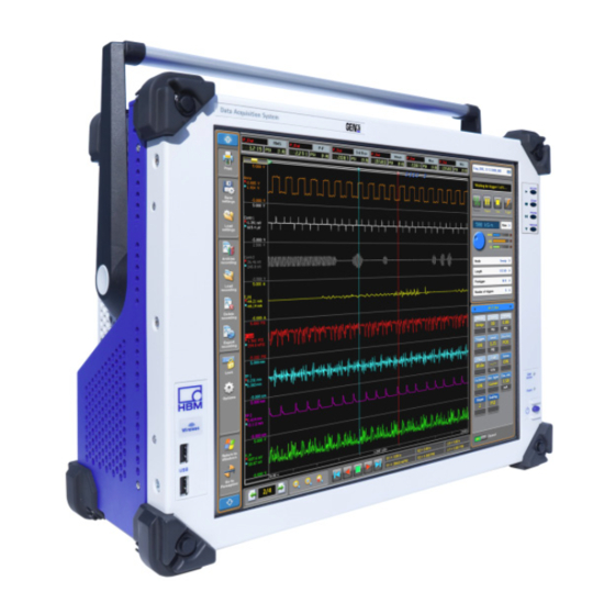
Page 76: Introduction
Welcome! You have made the right choice; your GEN3i Portable Data Recorder is one of the most sophisticated and powerful systems on the marketplace and demonstrates the high quality HBM has to offer. GEN3i is an all-in-one, field- ready, feature-packed unit. - Page 77 GEN3i Data archiving is a challenging task when doing data acquisition. GEN3i offers a variety of storage and archiving options. Internally GEN3i is equipped with a 480 GB solid state Hard Drive. The instrument can be connected to a network using built-in wired and wireless interfaces.
-
Page 78: Mainframe Overview
All mainframes share many of the GEN series features. Besides the listed differences in the table above, other differences are: mechanical form factor, power consumption, integrated PC or tethered PC use, etc. For technical details, please refer to the individual mainframe data sheets. I3763-3.1 en HBM: public... -
Page 79: Mainframe Feature Comparison
- GEN2I - 2, 1 - GEN5I - 2, - GEN7T - 2, 1 - GEN16T - 2 - GEN7T - 2 and Exceptions 1 - GEN16T - 2 with IM2 1-GEN3I-2 and 1-GEN7I-2 1-GEN3t-2, 1-GEN7tA-2 and 1-GEN17tA-2 Note Grey columns are end of life systems. - Page 80 - GEN7T - 2 and 1 - GEN16T - 2 - GEN7T - 2 and Exceptions 1 - GEN16T - 2 with IM2 1-GEN3I-2, 1-GEN7I-2, 1-GEN3t-2, 1-GEN7tA-2 and 1-GEN17tA-2 Note Grey columns are end of life systems. I3763-3.1 en HBM: public...
-
Page 81: Hardware
200 MB/s. Check the detailed specifications of the individual acquisition cards to see whether it uses the fast data storage bus of the GEN3i if aggregate streaming rates above 200 MB/s are required. -
Page 82: Input Cards
The single synchronization connector allows for the direct connection of one Slave to the GEN3i or the GEN3i to be a Slave within any Master/Slave multi mainframe setup. 6.3.4 Thermal protection Every GEN series mainframe supports a feature called Thermal Shutdown. - Page 83 At next power-on of the GEN series system, the automatic thermal shutdown event will be presented to the user again and can be found in the error diagnostics of the mainframe. I3763-3.1 en HBM: public...
-
Page 84: Acquisition
GEN3i Acquisition GEN3i is a multi-channel Portable data recorder. It provides real-time data for waveform and meter displays. It allows unlimited recording duration and file size at a high streaming rate. Statistics are performed in real-time. Its extreme performance signal conditioning includes both Bessel and Butterworth anti- alias filters to provide excellent response. - Page 85 Unlike competitive systems, the GEN3i has no need to inspect gigabytes of information just to display the last kilobyte. While zooming in, more detail is displayed while always maintaining the highest visible resolution.
-
Page 86: Signal Conditioning
GEN3i Signal conditioning GEN3i supports common analog sensors with the highest performance signal conditioning available. All inputs are sampled simultaneously for exact time correlation, and the front ends deliver a typical maximum static error of 0.1%. Plug-and-play hardware discovery with scalability to any number of channels. -
Page 87: Data Storage
GEN3i Data storage In addition to mega samples of on-board RAM, record data directly to the GEN3i hard drive, or USB device. In addition you can archive your data on a USB stick, or to a network server over the Gigabit Ethernet. GEN3i always stores to on- board high-speed RAM. -
Page 88: Pc Section
GEN3i PC Section GEN3i has a built-in industrial PC. This PC provides all the standard features that you would expect from an industrial grade quality PC. Features include: ® Intel Core™ i5 processor (3 generation) Ivy Bridge M chipset (x77) ®... -
Page 89: Perception Software
GEN3i Perception Software Perception Software is installed on your GEN3i for control, analysis, archiving and reporting. The GEN3i has two modes of operation. During operation, you can choose between these two modes. Primary mode: Instrument Panel - for daily use... - Page 90 Figure 6.6: Toolbar Go to perception When in Perception, navigate to the menu item File, select Switch to Instrument Panel and confirm the action to switch to the Instrument Panel. Figure 6.7: Switch to Instrument Panel option I3763-3.1 en HBM: public...
-
Page 91: Windows Logon Password And Remote Desktop Access
Perception, which is provided separately. Note For general information on the Instrument Panel, please refer to the user manual for the Instrument Panel Software for GEN3i, which is provided separately. Note The settings from the advances features can be changed when switching to the Instrument Panel mode. -
Page 92: Perception Language Settings
Various program settings are stored in the Perception preferences. These settings include, but are not limited to, Perception language, start-up options, options for updates, video information, display settings, etc. Figure 6.8: Preferences dialog To open the Preferences dialog: Click Preferences... in the File menu. I3763-3.1 en HBM: public... - Page 93 In the User Interface Mode drop-down list, you can select from the following choices: Figure 6.10: User Interface Mode area (detail) A Auto The software detects which system Perception is being run on and starts in the corresponding mode. I3763-3.1 en HBM: public...
- Page 94 PCs, GEN5i and GEN7i. C Instrument Panel The Instrument Panel GUI, which is the default option for GEN2i and GEN3i. For more information, please refer to Figure 6.7 "Switch to Instrument Panel option" on page 90. Perception will start in the defined User Interface mode.
-
Page 95: Setting Up The Gen3I
GEN3i 7 Setting up the GEN3i PC connections GEN3i has a PC motherboard inside. This PC motherboard has a lot of connections that can be used to connect other devices to the GEN3i system. Figure 7.1: PC connections 3 * RJ45 - 1 Gbit network ports See "Communication and control"... -
Page 96: Usb 3.0 And Usb 2.0 Ports
One external digital monitor can be connected to each of these display port connectors. A total of three external monitors can be connected simultaneously. However, the DVI monitor is a cloned version of the built-in screen in this setup. I3763-3.1 en HBM: public... -
Page 97: Sound, Microphone, Speakers
GEN3i 7.1.3 Sound, microphone, speakers The GEN3i unit is delivered with only one internal (mono) speaker. For other audio options, the GEN3i unit has connectors (3.5 mm jack) for line-in, speaker-out and microphone-in. As soon as the speaker-out connector is used by plugging a 3.5 mm jack into it, the internal speaker is disabled. -
Page 98: Removing And Installing Input Cards
(ESD). ESD damage is quite easy to induce, often hard to detect and always costly. Therefore, we must emphasize the importance of ESD preventions when handling a GEN3i system, its connections or a plug-in card. CAUTION The GEN3i Portable data recorder is factory-calibrated as delivered to the customer. -
Page 99: Installing Cards
7.2.2 Installing cards To install a card: Power off the GEN3i system and remove the power input cable. Ensure that the ejector levers are in the farthest outermost position, tilting away from the card. Slide the card into its guide rails until the ejectors contact the perforated metal strips on the left and right. - Page 100 Screws must be locked to meet CE emissions. Figure 7.6: Blind panel (1-G009-2) WARNING Any empty slots must be covered with a blind panel with a thermal strip on the back to meet the cooling requirements of the mainframe. I3763-3.1 en HBM: public...
-
Page 101: Handle
GEN3i Handle The handle handles are used to carry the GEN3i system. Only carry the instrument when the handle is in the upright position. Figure 7.7: GEN3i with handle in the upright position I3763-3.1 en HBM: public... -
Page 102: Turning The Handle
Turning the handle You can turn the handle to act as built-in stand: 1 Put instrument on a flat surface. 2 Push in the button on both sides of the handle. Figure 7.8: Button on the handle I3763-3.1 en HBM: public... - Page 103 The handle will snap into one of its fixed positions (30° indexing). Figure 7.9: GEN3i multiple handle positions 3 Gently turn over the GEN3i unit so that it rests on the handle's flat surface. I3763-3.1 en HBM: public...
- Page 104 GEN3i 4 The GEN3i unit is now supported by its handle. Figure 7.10: GEN3i supported by its handle When the handle is turned to back of the unit, it can be used to lift the front of the instrument so that the display is angled towards the user. In Figure 7.10, the angle between the display and horizontal axis is about...
-
Page 105: Feet
GEN3i Feet GEN3i stands on four rubber feet in normal operation position. Two feet are positioned at the rear and two are at the front of the instrument. Two extra, foldable front feet can be used to lift the instrument front so the display angle is towards the user. -
Page 106: Probe Calibration
GEN3i Probe calibration The GEN3i mainframe is provided with a probe calibration output. This output can be used to calibrate probes used in combination with the Genesis High- speed measurement system. The probe calibration output drives a calibration signal with the following... - Page 107 Figure 7.13 below shows how the signal should look. When the trimmer is positioned incorrectly, undershoot or overshoot is seen in the signal. Figure 7.13: Trimming of response - Incorrect and correct waveform responses Incorrect - Undershoot Correct Incorrect - Overshoot I3763-3.1 en HBM: public...
-
Page 108: Dc Power Output
Connector pinning QuantumX compatible; only GND and PWR signals connected Output Power 15 Watt Output Voltage > 11 V; Typically 11.5 V to 12 V Maximum Output Current 1.4 A; Limited current and short circuit protected I3763-3.1 en HBM: public... - Page 109 PIN 2 - Reserved/not connected PIN 3 - GND PIN 4 - Reserved/not connected PIN 5 - Reserved/not connected PIN 6 - Reserved/not connected PIN 7 - PWR PIN 8 - Reserved/not connected Figure 7.15: GEN3i DC power output I3763-3.1 en HBM: public...
-
Page 110: Digital Event/Timer/Counter
Not all GEN series acquisition cards have support for the Digital Event/ Timer/Counter connector. Only the acquisition cards that have support listed in their specification sheet will be able to use this connector. (See appendix "B3762–5.1 en (GEN3i Portable Data Recorder)" on page 365 for more details). I3763-3.1 en HBM: public... - Page 111 44 pin, female D-type connector, AMP HD-22 series (Tyco/TE connectivity: 5748482-5) Mating cable connector 44 pin, male D-type connector, HDP-22 series type (Tyco/TE connectivity: 1658680-1) Output power Voltage 5 ± 0.5 V DC Maximum current 0.5 A I3763-3.1 en HBM: public...
- Page 112 Functions See specifications of acquisition cards that support these outputs Output levels TTL compatible; 0 V < Low < 0.6V; 2 V < High < Output resistance 49.9 Ω ± 1% Maximum output current 50 mA, short circuit protected I3763-3.1 en HBM: public...
- Page 113 PIN 21 - Event Input 9B PIN 43 - +5 V Power PIN 22 - Event Input 10B & Reset Timer/Counter 1B PIN 44 - +5 V Power Figure 7.19: Pin diagram for Digital Event/Timer/Counter connector I3763-3.1 en HBM: public...
-
Page 114: Isolated Event Adapter
It has a maximum 230 V RMS isolation spec and comes with a connection cable to directly connect the adapter to the mainframe. The adapter isolates all input and output events and Timer/Counter pins. See appendix "Mainframe adapters" on page 762 for detailed usages and specification of this adapter. I3763-3.1 en HBM: public... -
Page 115: Torque/Rpm Adapter
RS422 Figure 7.21: Block diagram and image HBM's Torque and RPM sensors come standard with RS422 digital output signals. As the GEN series Digital Event/Timer/Counter inputs are TTL inputs, signal need to be converted to make both side able to work together. - Page 116 +5 V Out +5 V IN Figure 7.22: Block Diagram Torque/RPM Adapter Using this adapter T12, T40 and alike torque transducer can be directly connected to the GEN series mainframe without additional need to build your own cables. I3763-3.1 en HBM: public...
- Page 117 Torque/RPM sensor both to a GEN series mainframe and any other receiving system, the T-function output renews the original signal with an RS422 transmit buffer. This setup garantees a point to point connection required for proper RS422 usage. I3763-3.1 en HBM: public...
-
Page 118: Getting Started
Front panel control Standby On GEN3i, the standby button is located on the front panel. When this button is pressed, the instrument state toggles between operating and standby mode. In standby mode, some power is consumed and the instrument is NOT disconnected from the AC supply. - Page 119 GEN3i Figure 8.2: Acquistion control - Detail Record Stop Pause Trigger I3763-3.1 en HBM: public...
- Page 120 Figure 8.3: USB 2.0 ports (located on the front of the unit) USB 2.0 ports Wireless adapter Wireless adapter For information on the Wireless adapter, please refer to "Wireless network" on page 122. I3763-3.1 en HBM: public...
-
Page 121: Getting Started
GEN3i Getting started When GEN3i is started up for the first time, the software starts and connects to the integrated GEN3i data acquisition unit automatically. The Instrument Panel starts in continuous mode and the acquisition unit starts in preview mode, meaning that incoming signals are monitored, but no data is stored. -
Page 122: Wireless Network
With data rates up to 300 Mbit/s, the adapter supports a comfortable wireless bandwidth. Below is a quick start procedure to connect GEN3i to your local network and a quick start procedure to disconnect GEN3i from a network. -
Page 123: Windows® 7: To Connect Gen3I To The Local Wireless Network
GEN3i ® 8.3.1 Windows 7: To connect GEN3i to the local wireless network: Start GEN3i. When GEN3i is fully booted, quit Perception. ® In Windows 7, access the Connect to a network dialog using one of the following options: ●... -
Page 124: Windows® 7: To Disconnect Gen3I From The Local Wireless Network
Remove the network connection ● Make the network connection a manual procedure (recommended when you do not want to connect GEN3i to the network automatically). For both options: Click Start, click Control Panel, click Network and Internet, click Network and Sharing Center and select the task Manage Wireless Networks. -
Page 125: Windows® 10: To Connect Gen3I To The Local Wireless Network
GEN3i ® 8.3.3 Windows 10: To connect GEN3i to the local wireless network: Start GEN3i. When GEN3i is fully booted, quit Perception. ® In Windows 10, access the Network & Internet dialog using one of the following options: By clicking Start ► Settings ► Network & Internet (see ●... - Page 126 GEN3i 3B Select the Wi-Fi option from the NETWORK & INTERNET window. Figure 8.5: Network and Internet options I3763-3.1 en HBM: public...
- Page 127 GEN3i 3A Click the Network icon in the task bar and select Network settings to open the advanced settings (see Figure 8.7) Figure 8.6: Network icon with context menu Network settings Network icon I3763-3.1 en HBM: public...
- Page 128 If the name (SSID) of the network is not broadcasted, a Hidden Network is listed. When connecting to the hidden network, the name has to be entered. Figure 8.7: Network and internet window (advanced settings) Hidden Network area I3763-3.1 en HBM: public...
-
Page 129: Windows® 10: To Disconnect Gen3I From The Local Wireless Network
Remove the network connection ● Make the network connection a manual procedure (recommended when you do not want to connect GEN3i to the network automatically). To remove a network: Click Start, click Settings, click Network & Internet, click Wi-Fi and select the option Manage Wi-Fi Settings. - Page 130 When the manual connection has been selected, you can still connect to the network, but you will need to do so manually. To connect to the network, click ® the Windows 10 networking icon in the task bar, select the Wi-Fi network and click Connect. I3763-3.1 en HBM: public...
-
Page 131: Acquisition And Storage
9 Acquisition and Storage Introduction Data acquisition hardware within the GEN3i is based on the concept of a recorder. A recorder consists of a number of acquisition channels that share the same basic recording parameters: sample rate, sweep length and pre- and post-trigger length. -
Page 132: Recording
Perception software, it is advised to read this section in combination with the corresponding sections in the Perception manual. The GEN3i/Perception combination provides the following acquisition controls: ● RUN The run command starts recording of data. Now the recorder(s) record(s) data until a stop command is issued. -
Page 133: Storage
GEN3i Storage The GEN3i provides two storage paths, as shown in Figure 9.1 on page 131: Store data in on-board RAM at high speed Transfer data directly at reduced speed to the controlling PC or (when installed) to a local disk. -
Page 134: More On Sweeps
If the last storage location of a segment is filled and acquisition is still taking place, the first storage location is overwritten with a new sample, followed by the second storage location, etc. I3763-3.1 en HBM: public... -
Page 135: Pre-Trigger Sweeps
Storage into the ring buffer can be stopped only by a “stop” signal from the recorder. This signal is called the "trigger". For more information on triggering, please refer to chapter “Digital Trigger Modes” on page 143. I3763-3.1 en HBM: public... - Page 136 To achieve this aim, a delay is introduced. Once the trigger condition is met, storage is stopped - not immediately, but only after a programmable delay counter has counted out. The memory now contains pre- trigger information and post-trigger information. I3763-3.1 en HBM: public...
-
Page 137: More On Continuous Data Storage
More on continuous data storage The most important difference between continuous data storage and sweeps in a GEN3i is the fact that sweeps are stored in on-board volatile RAM, while continuous storage takes place on the controlling PC's hard disk (or local hard disk when installed). - Page 138 In this mode, the lead-out is specified which is basically the same as the post-trigger segment in a sweep recording. Stop on trigger The continuous mode operates like a pre-trigger sweep, but with storage on the PC hard disk, not in volatile memory. I3763-3.1 en HBM: public...
-
Page 139: Time Base
The selections above can be found in the Perception software in the Settings Sheet ► Memory&Timebase ► Mainframe ► Clock Base and are therefore mainframe-wide, i.e. the same for all recorders. A binary clock base is a useful time base settings when doing FFTs (frequency domain analysis). I3763-3.1 en HBM: public... -
Page 140: Time Base Settings For Ffts
40.960 kHz and a frame length of 8192 samples result in a 5 Hz bin size, i.e. the spectral lines are 5 Hz from each other. "Nice" values are considered to be "minor" values that easily fit in "major" values for (grid) display purposes. I3763-3.1 en HBM: public... - Page 141 12.5 51200 12.5 6.25 40960 25600 12.5 6.25 3.125 20480 12800 12.5 6.25 3.125 1.5625 1024 1.25 5120 1.25 0.625 4096 2560 1.25 0.625 0.3125 2048 0.25 1280 1.25 0.625 0.3125 0.0156 1024 1000 0.25 0.125 I3763-3.1 en HBM: public...
-
Page 142: Additional Information
Δf = 5 Hz The maximum frequency component that can be measured is 40.96 kHz / 2 = 20.48 kHz The FFT X-scale (frequency) will start at 5 Hz, end at 20480 Hz, and has 4096 points. I3763-3.1 en HBM: public... -
Page 143: 10 Digital Trigger Modes
In this chapter, the trigger capabilities of the GEN3i data acquisition system will be explained in full detail. Each channel within a recorder can trigger this recorder. This functionality is realized by combining all channel triggers into a logical OR combination. -
Page 144: Understanding Digital Triggering
Figure 10.1: Single-level trigger detector The delay register in front of the ALU is used to compare the ADC value with “older” values. This means that triggering does not react to specific levels, but to the differential signal or slope. I3763-3.1 en HBM: public... - Page 145 For the advanced trigger modes, the single-level trigger detector with programmable hysteresis has been implemented twice to provide a dual- level trigger detector. Levels are usually referenced as primary trigger level and secondary trigger level. I3763-3.1 en HBM: public...
-
Page 146: Valid Trigger Conditions
Trigger does not occur until a sample is actually above the required level. Since the trigger detector requires a level crossing, no trigger occurs when a signal is above the set level when recording starts. This is depicted in Figure 10.2 (C). I3763-3.1 en HBM: public... - Page 147 (H) is used to “arm” the level trigger detector. Otherwise stated, the trigger level has been expanded to be a trigger zone that spans multiple levels. Trigger Trigger Trigger level Trigger Hysteresis level Set hysteresis Sample Reset hysteresis Figure 10.3: Trigger level hysteresis I3763-3.1 en HBM: public...
-
Page 148: Trigger Modes
GEN3i 10.3 Trigger modes Using the various trigger modes, GEN3i data acquisition system is expanded to an extremely versatile transient recorder. The trigger circuits may be configured to trigger on many types of phenomena. In this section, the different trigger modes and their extensions are discussed in detail. -
Page 149: Dual Trigger Mode
Primary level: any value within the input range Secondary level: any value within the input range Direction: positive or negative for primary level; secondary level is automatically set to the opposite direction Hysteresis: any relevant value is used for both levels. I3763-3.1 en HBM: public... -
Page 150: Window Trigger Mode
The Window trigger mode is very useful if a periodic signal is monitored and GEN3i must be triggered on peak level changes. This mode is most effective on uni-polar signals, e.g. a TTL level pulse train. For bi-polar signals, the dual- window trigger mode is more suited as described in the following section. -
Page 151: Dual-Window Trigger Mode
Primary level: any value within the input range Secondary level: any value within the input range Direction: positive or negative for primary level; secondary level is automatically set to the opposite direction Hysteresis: any relevant value is used for both levels. I3763-3.1 en HBM: public... -
Page 152: Sequential Trigger Mode
Primary level: any value within the input range Secondary level: any value within the input range Direction: positive or negative for primary level; secondary level is automatically set to the opposite direction Hysteresis: any relevant value is used for both levels. I3763-3.1 en HBM: public... -
Page 153: Trigger Qualifier
When in qualifier mode, the output of the trigger detector is sent to a qualifier line of the recorder trigger logic. For more information on the recorder trigger features, please refer to "Recorder and system trigger" on page 162. I3763-3.1 en HBM: public... -
Page 154: Trigger Add-Ons
The slope detector is also known as differentiator or dY/dt detector. The output of the slope detector is the difference between the newest sample and the sample that was recorded the given number of sample intervals ago. I3763-3.1 en HBM: public... -
Page 155: Pulse Detector
If, after crossing, the condition of the comparator is stable for at least a specified period of time, the crossing is a valid trigger condition, i.e. it is a long enough pulse that must be recorded, and a trigger is generated. I3763-3.1 en HBM: public... -
Page 156: Hold Off
This can be used to generate only one trigger on a slowly decaying repetitive signal, or to eliminate the effect of after-ringing. Using a 16 bit counter, triggering can be disabled for as long as 6.5535 seconds when sampling at 10 kS/s. I3763-3.1 en HBM: public... -
Page 157: Interval Timer
At 1 MS/s sample rate, this results in a maximum of 65.535 millisecond. Interval timer - Less This interval time mode is fairly straightforward. When the second trigger event is within the set time interval, a trigger is generated. I3763-3.1 en HBM: public... -
Page 158: Interval Timer - More
The reset moments are denoted with a dotted line and the actual trigger moment is denoted with a straight line. Figure 10.14: Interval timer - More Trigger Interval I3763-3.1 en HBM: public... -
Page 159: Interval Timer - Between
A second trigger event occurs before Interval Timer 1 has expired and the timer is reset. 10 Interval Timer 1 expires and Interval Timer 2 is started. 11 A trigger event occurs before Interval Timer 2 expires and a trigger is generated. Trigger I3763-3.1 en HBM: public... -
Page 160: Interval Timer - Notbetween
A trigger event occurs within the second interval. Interval Timer 1 is restarted. Interval 2 Interval Timer 1 expires and Interval Timer 2 is started. 10 Interval Timer 2 expires and a trigger is generated. A Trigger I3763-3.1 en HBM: public... -
Page 161: Event Counter
As a last resource, the event counter can be used. The event counter counts all channel triggers that have been detected and generates a system trigger when the count equals a user defined value. I3763-3.1 en HBM: public... -
Page 162: Recorder And System Trigger
Each input card can select to use the external trigger as a trigger source. ● Qualifier 1 through N: These are the qualifiers as described above: Please refer to chapter "Trigger qualifier" on page 153. I3763-3.1 en HBM: public... - Page 163 Master/Slave function. When in use, a recorder can put the recorder trigger on the Master/Slave trigger line and/or pick up the trigger from the Master/ Slave trigger line. When Master/Slave operation is not used, this line functions just like the other three trigger lines. I3763-3.1 en HBM: public...
-
Page 164: Channel Alarm
The output of the alarm detector is sent to an alarm line and combined (OR-ed) with alarm conditions of the other channels and recorders. The result is available as an external output located on the mainframe controller. I3763-3.1 en HBM: public... -
Page 165: 11 Interface/Controller
D Master/Slave synchronization (optical) The Interface/Controller has a unique communication section with one standard Ethernet interface, one optical Ethernet interface with two activity LEDs and a Master/Slave interface with two activity LEDs and the I/O connector. I3763-3.1 en HBM: public... -
Page 166: Communication And Control
100 or 10 Mbit/s network Network connection with Blinking connection active data exchange Network connection with no 1 Gbit/s network connection data exchange Network connection with 1 Gbit/s network connection Blinking active data exchange I3763-3.1 en HBM: public... -
Page 167: Network Protocols And Ports
Depending on storage speed, Ethernet Link speed and limited by network bandwidth. Currently maximum 120 MB/s on 1 Gbit Ethernet and 250 MB/s on 10 Gbit Ethernet ports. Other protocols ARP, DNS When supported on the network setup I3763-3.1 en HBM: public... -
Page 168: Using The 1 Gbit Option Connections
Standard the SFP receiver housing is part of the mainframe. Inserting a SFP module enables the use of optical Ethernet. The SFP is offered using two different wavelengths: 850 nm or 1320 nm. See appendix "Fiber optic cables and SFPs" on page 755 for detailed usage and specifications. I3763-3.1 en HBM: public... -
Page 169: Master/Slave Synchronization
(user software action to trigger all mainframes synchronously). Calculated channel trigger exchange (requires Perception V6.50 or higher). For detailed specification, please refer to appendix "B3762–5.1 en (GEN3i Portable Data Recorder)" on page 365. The GEN series can be operated as a fully synchronized Multi-Mainframe system with multiple mainframes using the Master/Slave synchronization connector. - Page 170 1 MW 250Vpk 1 MW 250Vpk 1 MW 250Vpk 1 MW 250Vpk 1 MW 250Vpk 1 MW 250Vpk 1 MW 250Vpk 1 MW 250Vpk 1 MW 250Vpk 1 MW 250Vpk 1 MW 250Vpk 1 MW 250Vpk I3763-3.1 en HBM: public...
- Page 171 LED indicators On the front panel of the Master/Slave Synchronization connector, two LEDs indicate the status of the link. icon is used to identify the signal detect function. icon is for data/synchronization identification. icon icon I3763-3.1 en HBM: public...
- Page 172 Table 11.2: Master/Slave card front panel LED indicators FRONT PANEL LED INDICATORS Status Description No valid characters detected/ No Link no optical signal detected Optical signal detection/ Alignment characters initialization detected Receiving data Receiving valid data I3763-3.1 en HBM: public...
-
Page 173: Connecting The Master/Slave Synchronization Connector
Slave mainframes. The master mainframe needs to be extended with one or more optional option carrier cards (G081). Each option carrier card can be extended with one or two Master output cards (G083). I3763-3.1 en HBM: public... - Page 174 Connect one of the connectors of the Master Output Card(s) (G083) to the Master/Slave synchronization connector of the first Slave mainframe. Connect one of the connectors of the Master Output Card(s) (G083) to the Master/Slave synchronization connector of the second Slave mainframe. I3763-3.1 en HBM: public...
- Page 175 Master/Slave synchronization connector of the third Slave mainframe. Connect one of the connectors of the Master Output Card(s) (G083) to the Master/Slave synchronization connector of the fourth Slave mainframe. If more mainframes are used repeat this setup until all Slave mainframes are connected. I3763-3.1 en HBM: public...
-
Page 176: Setting The Master/Slave Operating Modes
Select the mainframe(s) that should be used as Slave. Double-click on the Master/Slave mode cell to open it for modification. In the drop-down list that appears, select Slave. To disable the Master/Slave operation and set the mainframe to Stand-alone mode: I3763-3.1 en HBM: public... - Page 177 Double-click on the Master/Slave mode cell to open it for modification. In the drop-down list that appears, select Stand-alone. HINT/TIP Cables do not have to be removed, as the mainframe does not use the connected cable during stand-alone mode. I3763-3.1 en HBM: public...
-
Page 178: Setting The Master/Slave Trigger
Receive trigger(s) from other mainframes, no triggers are transmitted. Transceive Transmit and receive trigger(s) from other mainframes. The settings are controlled in the block diagram or through the Master/Slave trigger setting in the sheet. Figure 11.8: Block diagram I3763-3.1 en HBM: public... - Page 179 In the Settings sheet, go to the Trigger group in the task pane and select Recorder. A list of available recorders is displayed in the settings area. Select the recorder that you want to set. Double-click on the Master/Slave trigger cell to open it for modification. I3763-3.1 en HBM: public...
- Page 180 GEN3i In the drop-down list that appears, select the setting that should be used. Figure 11.10: Master/Slave trigger list I3763-3.1 en HBM: public...
-
Page 181: Synchronizing A Master/Slave Setup To External Time Sources
Double-click on the Sync source cell to open it for modification. In the drop-down list that appears, select the synchronization source that should be used. For information on how to check synchronization, please refer to appendix "Master/Slave synchronization verification procedure" on page 901. I3763-3.1 en HBM: public... -
Page 182: I/O Connector
Figure 11.12: Interface/Controller I/O connector (trigger in/out, clock in, event out, start/stop) The I/O connector comes with a BNC breakout cable for direct BNC cable connection to each function (see Figure 11.13). Figure 11.13: BNC breakout cable I3763-3.1 en HBM: public... -
Page 183: I/O Connector Input Overvoltage Protection
The clamping diodes and other parasitic capacitors do create a capacitive load on your signal source and limit the signal bandwidth. To reach the required bandwidths detailed compensations are made not addressed in this block diagram. I3763-3.1 en HBM: public... -
Page 184: I/O Connector Functions And Connector Pinning
This output is software selectable between Alarm Out and Recording Active Out. When alarm is selected, the output is driven by channel alarm detectors. When recording active is selected, the output is “high” while a recording is in progress. I3763-3.1 en HBM: public... - Page 185 The External start/stop (see Figure 11.15) settings are located in the General/ Mainframe setting page of the settings spreadsheet. The settings are only visible when Advanced (All settings) is enabled (see Figure 11.16). Figure 11.15: General/Mainframe settings External start/stop mode columns I3763-3.1 en HBM: public...
- Page 186 When selecting Disabled, the signal on the input is ignored. When selecting Rising Edge, a start is initiated when a rising edge is detected. When selecting Falling Edge, a start is initiated when a falling edge is detected. I3763-3.1 en HBM: public...
- Page 187 Start event will not be detected for 100 ms. If, however, a Stop event occurred immediately after a Start event had been detected, the Stop event would be detected and processed immediately after the acquisition is started due to the Start event. I3763-3.1 en HBM: public...
-
Page 188: Option - Optical 1 Gbit Ethernet Interface
SFP label - 850 or 1310 nm Note 1310 nm Single Mode (SM) and 850 nm Multi Mode (MM) optical fiber transceivers use specific cables and connectors. Therefore, make sure that the correct mode/specification of fiber optic cable is used. I3763-3.1 en HBM: public... - Page 189 For specifications and ordering information, please refer to "B3762–5.1 en (GEN3i Portable Data Recorder)" on page 365. For information on how to install and remove the SFP module, please refer to section "Installing a 1 Gbit SFP/10 Gbit SFP+ Module" on page 197.
-
Page 190: Option - 10 Gbit Ethernet Interface
Two interfaces cannot be used at the same time for storage purposes nor can they be used at the same time for communication purposes. I3763-3.1 en HBM: public... - Page 191 ACT (green): Ethernet Activity (on when active) LNK (green): Ethernet Link (on when active) 10 Gbit (green): Ethernet Speed 10 Gigabit (always on) 1 Gbit (green): Ethernet Speed 1 Gigabit (always on) CH A = NIC1 (Requires SFP+ module, not shown) I3763-3.1 en HBM: public...
- Page 192 SFP label - 850 or 1310 nm Note 1310 nm Single Mode (SM) and 850 nm Multi Mode (MM) optical fiber transceivers use specific cables and connectors therefore please check the correct mode/specification of fiber optic cable is used. I3763-3.1 en HBM: public...
- Page 193 A PC with an optical Ethernet interface which has SFP+ support is connected via optical cable to the interface of the 10 Gbit Ethernet card option of the GENDAQ unit. This setup utilizes the higher speed communication of the 10 Gbit Ethernet card for communication with Perception. I3763-3.1 en HBM: public...
- Page 194 PC. The correct connection is not always an SFP+ module but there must be a network card or adaptor installed that supports the same specifications as the SFP+ modules used on the GENDAQ side. I3763-3.1 en HBM: public...
- Page 195 With the 10 Gbit Ethernet option installed and ready to go you will be provided with the two following interfaces for selection: Optical 10 Gbit NIC1 Optical 10 Gbit NIC2 In Perception these interfaces are available in the Settings menu > Mainframe Network Setup see Figure 11.23 below. I3763-3.1 en HBM: public...
- Page 196 Perception will be the interface used for communication with Perception. For the 10 Gbit Ethernet card check the box for the Optical 10 Gbit NIC1 or 2. Click Apply then Close when done. I3763-3.1 en HBM: public...
-
Page 197: Installing A 1 Gbit Sfp/10 Gbit Sfp+ Module
10 Gbit Ethernet card. Warnings Before installing this device, please read and make sure that you have understood the following warnings, which are specific for this device. I3763-3.1 en HBM: public... - Page 198 Take steps to avoid such an occurrence. CAUTION HBM uses state-of-the-art electronic components in its equipment. These electronic components can be damaged by discharge of static electricity (ESD). ESD damage is quite easy to induce, often hard to detect, and always costly.
-
Page 199: Installation Steps
GEN3i Installation steps First, make sure that the mainframe unit is switched off. Then locate the available SFP slot and remove the plastic plug (if inserted). Figure 11.24: Interface/Controller SFP location Interface/Controller SFP location Remove cap I3763-3.1 en HBM: public... - Page 200 Grasp the module between fingers and thumb at the end with the small black removal bar. Push the back end into the available SFP slot, until you hear a click. Figure 11.25: Insert device in SFP slot Insert device I3763-3.1 en HBM: public...
- Page 201 GEN3i Embedded software detects the device and automatically connects to it when the mainframe is powered on. Figure 11.26: SFP slot with device Device being inserted I3763-3.1 en HBM: public...
- Page 202 The spring-loaded removal bar releases the SFP from the front panel. Figure 11.27: SFP slot - Remove device Remove device Then, if available, replace the small plastic plug to protect the optical inlet. I3763-3.1 en HBM: public...
-
Page 203: Option - Irig And Irig/Gps Time Synchronization
Option - IRIG and IRIG/GPS time synchronization 11.7 The IRIG cards provide precise time and frequency reference to the GEN3i data acquisition system. Time is acquired from either the GPS satellites using an antenna / receiver (IRIG/GPS model only) or from time code signals, typical IRIG B. -
Page 204: Gps Antenna System Rules
An ideal position has no obstructions above 10 degrees above the horizon. The total blockage of the sky (due to buildings, mountains, etc.) should be less than 50%. If less than 50% of the sky is visible to the antenna, contact Symmetricom for further assistance. I3763-3.1 en HBM: public... -
Page 205: Rule 2: Is A Gps Line Amplifier Needed
A grounding strap should be used if you cannot connect directly to a grounding plate. Caution If you are not comfortable designing your own lightning protection system, seek professional assistance. This is only a guide. I3763-3.1 en HBM: public... -
Page 206: Rule 4: Interconnect Cables
Multiple site installations may be done more efficiently using bulk cable and a connector installation tool kit. For more information about multiple antenna site installations or general questions about GPS antenna system installation, please contact Symmetricom’s Customer Technical Assistance Center. I3763-3.1 en HBM: public... -
Page 207: 12 Input Cards
18 200 k GN840B 24 500 k GN1640B 24 500 k GN3210 24 250 k GN3211 20 k GN4070 250 k GN6470 20 k (1) This card supports up to four fiber optic isolated transmitter channels. I3763-3.1 en HBM: public... - Page 208 500 k 2 GB GN1640B 500 k 2 GB GN3210 250 k 2 GB GN3211 20 k 200 MB GN4070 512 MB GN6470 512 MB (1) This card supports up to four fiber optic isolated transmitter channels. I3763-3.1 en HBM: public...
- Page 209 100 MS/s 14 bit 1800 V RMS 240 V AC GN113 GN401 120/ 25 MS/s 15 bit 1800 V RMS 240 V AC GN114 GN402 Externally 100 MS/s 14 bit User application isolated defined 12 V DC I3763-3.1 en HBM: public...
-
Page 210: Acquisition Card Feature Comparison
- GN813 - 2/1 - GN814 - 2 - GN1610 - 2/1 - GN1611 - 2 1-GN401-2 1-GN402-2 1-GN410-2/1-GN411-2 1-GN412-2/1-GN413-2 1-GN440-2/1-GN441-2 1-GN610-2/1-GN611-2 Option Option 1-GN610B-2/1-GN611B-2 1-GN815-2/1-GN816-2 Option Option 1-GN840B-2/1-GN1640B-2 1-GN3210-2/1-GN3211-2 1-GN4070-2/1-GN6470-2 Note Grey columns are end of life cards. I3763-3.1 en HBM: public... -
Page 211: Isolated 1Kv Input Cards
The two Timer/Counters and the G070A torque/RPM adapter allow for direct interfacing to HBM torque transducers or other torque and speed sensors. Besides the instantaneous values, the real-time cycle detection allows for cycle based real-time calculations like: TrueRMS on all analog channels; torque, angle, speed on all Timer/Counter channels. -
Page 212: Gn611B, Isolated 1Kv 200Ks/S Input Card With Real-Time Formula Database
The two Timer/Counters and the G070A torque/RPM adapter allow for direct interfacing to HBM torque transducers or other torque and speed sensors. Besides the instantaneous values, the real-time cycle detection allows for cycle based real-time calculations like: TrueRMS on all analog channels; torque, angle, speed on all Timer/Counter channels. -
Page 213: Gn610, Isolated 1Kv 2Ms/S Input Card
The two Timer/Counters together with the GEN series mainframe Digital Event/ Timer Counter connector and the G070A torque/RPM adapter allow for direct interfacing to HBM torque transducers or other torque and speed sensors. For specification and ordering information, please refer to "B3618-4.2 en (GEN series GN610)"... -
Page 214: Gn611, Isolated 1 Kv 200Ks/S Input Card
The two Timer/Counters together with the GEN series mainframe Digital Event/ Timer Counter connector and the G070A torque/RPM adapter allow for direct interfacing to HBM torque transducers or other torque and speed sensors. For specification and ordering information, please refer to "B3716-4.2 en (GEN series GN611)"... -
Page 215: Using The Gn610/Gn611 And Gn610B/Gn611B
Preferably, the shield should be connected to the chassis of the measurement Genesis High Speed equipment. Alternatively, the shield could also be connected to the chassis of the object under test. Figure 12.1: Shielded cable principles I3763-3.1 en HBM: public... - Page 216 GEN3i HBM KAB290 cables are designed to meet this setup: Shield yellow 2 wires 0.75mm Red and black Shield Cable isolation Isolation Wire to wire Shield to wire Figure 12.2: Shielded cable setup Typical conducted immunity disturbance (10 V RMS, Clamp)
- Page 217 WARNING Disconnect voltages before removing the card from the system. The measuring circuit can carry hazardous voltages and should be disconnected before the card is removed from the card slot of the measurement system. I3763-3.1 en HBM: public...
- Page 218 (see Figure 12.5). All cables used with the 1kV card must support 1000 V DC (or 1000 V AC peak) and 600 V CAT II. All required cables and connectors can be found in the appendix “Options, to be ordered separately” on page 728. I3763-3.1 en HBM: public...
-
Page 219: Understanding The Gn610/Gn611 And Gn610B/Gn611B Category Rating
1.390 2.210 1.550 2.500 4.000 > 150 ≤ 300 1.390 2.210 3.310 2.500 4.000 6.000 > 300 ≤ 600 2.210 3.310 4.260 4.000 6.000 8.000 > 600 ≤ 1 000 3.310 4.260 6.600 6.000 8.000 12.000 I3763-3.1 en HBM: public... -
Page 220: Understanding The Gn610/Gn611 And Gn610B/Gn611B Input
(Not) using probes: Using passive voltage probes together with balanced isolated inputs is very difficult and not recommended. The main reason for this is that there is no ground reference for the probe to divide the input voltage. I3763-3.1 en HBM: public... - Page 221 Example2: Since U IN(-) is not divided, there are very strict consideration on how signals can be attached. Assume the U IN(+) and U IN(-) are reversed by accident. We can calculate U and U IN(-). I3763-3.1 en HBM: public...
-
Page 222: Using The High Precision Differential Probe
Different to standard probes the HDP uses a balanced input divider, that matches both the resistive and capacitive characteristics of the GN610B/ GN611B/GN610/GN611 acquisition cards. Therefore users do not need to perform probe compensations before using this probe. I3763-3.1 en HBM: public... - Page 223 In this setup the output of the probe is dividing the input U to earth on both inputs. WARNING Make sure when using such a probe the U+ and U- of the GN610B/GN611B/ GN610/GN611 channel never exceeds the specification of 1000 V DC. I3763-3.1 en HBM: public...
-
Page 224: Measuring Currents
Current Transducer Ground Power Supply mA Signals, use KABXXX Cables DC AC Power Converter Power PTP1 PTP2 Electric Motor Current Transducer GEN7tA KABXXX Cable Connector for CT Cable Current Transducer Figure 12.12: Current transducer connection diagram I3763-3.1 en HBM: public... -
Page 225: Gn610/Gn611, Gn610B/Gn611B Isolation And Type Testing
1000 V RMS with respect to the chassis. If one channel has its common mode at +1000 V and one at -1000 V (with respect to chassis), the voltage between the two channels is 2000 V. The standards at which the card is certified is IEC61010-1:2010 and IEC61010-2-30:2010. I3763-3.1 en HBM: public... - Page 226 (personal safety). Isolation between channels is BASIC, since a channel is not accessible. Therefore, there is no direct risk to users (product safety). REINFORCED or DOUBLE isolation has higher test values than BASIC isolation. I3763-3.1 en HBM: public...
-
Page 227: Channel To Chassis Isolation Test
REINFORCED. The test value for 1000 V RMS is lower and therefore also covered by this test. Tests are conducted for one minute. For details, please refer to IEC61010. 3510 V RMS Isolated channel Isolated channel Chassis Figure 12.14: AC type test channel to chassis I3763-3.1 en HBM: public... - Page 228 GEN3i 4935 V DC Isolated channel Isolated channel Chassis Figure 12.15: DC type test channel to chassis I3763-3.1 en HBM: public...
-
Page 229: Channel To Channel Isolation Test
REINFORCED. The value for 2000 V RMS BASIC is lower and therefore also covered by this test. Tests are conducted for one minute. For details, please refer to IEC61010-1. Isolated channel 4935 V DC Isolated channel Chassis Figure 12.16: DC type test channel to channel I3763-3.1 en HBM: public... - Page 230 GEN3i Isolated channel 3510 V RMS Isolated channel Chassis Figure 12.17: AC type test channel to channel I3763-3.1 en HBM: public...
-
Page 231: High Potential Test
Channels 1, 3 and 5 all connected to chassis ground. 1500 V RMS Isolated channel Chn 1, 3, 5 Isolated channel Chn 2, 4, 6 Chassis Figure 12.18: Hipot testing Channels 1, 3 and 5 I3763-3.1 en HBM: public... - Page 232 GEN3i Isolated channel Chn 1, 3, 5 Isolated channel Chn 2, 4, 6 Chassis 1500 V RMS Figure 12.19: Hipot testing Channels 2, 4 and 6 I3763-3.1 en HBM: public...
-
Page 233: Engineering Tests
GEN3i Engineering tests Besides the type tests and the production tests, HBM has also performed several engineering tests to verify the robustness of the design during the engineering design qualification phase. Component tests Every component crossing the isolation barrier is tested and/or examined to make sure it will pass the type test. -
Page 234: Gn610/Gn611, Gn610B/Gn611B Protection Mechanisms
± 1000 V for all ranges, except for the ± 1000 V range that is limited to ± 1250 V. Exceeding these limits can damage the input card. GN610/GN611 and GN610B/GN611B input overload protection The input section has several methods to protect against voltage overload on the input. I3763-3.1 en HBM: public... - Page 235 +12V -12V +12V ≤ ±5V +12V > ±5V 1 / 100 -12V -12V Compare f(x1...x n ) +12V -12V +12V ≤ ±5V > ±5V 1 / 100 -12V Figure 12.22: Input overload protection - Schematic diagram I3763-3.1 en HBM: public...
-
Page 236: Thermal Monitor Of The Input Channels
Disconnecting from the external signal source is done by grounding the input. When inputs are grounded, the only connections to the external signal are the input connectors and the input pin of the ground relay. I3763-3.1 en HBM: public... -
Page 237: Thermal Shutdown In Critical Conditions
10 range Shutdown the Add TimeMark to Add TimeMark to Add TimeMark to Add TimeMark to complete system recording file recording file recording file recording file Wait 2 seconds Figure 12.23: Automatic thermal overload response I3763-3.1 en HBM: public... -
Page 238: Restore Range Selected By User Automatically
If the overload is permanent, the system keeps on automatic ranging to reduce the dissipated heat. The system then restores the range selected by the user, causing overheating again and thereby restarting the automatic ranging process again. This cycle will repeat forever until the overload condition disappears. I3763-3.1 en HBM: public... -
Page 239: Isolated Basic/Iepe Cards
1000 V RMS CAT III (1000 V RMS common mode) measurement range is created. The use of current clamps allow for direct current measurements. For specification and ordering information, please refer to "B3997-1.1 en (GEN series GN815)" on page 598. I3763-3.1 en HBM: public... -
Page 240: Gn816, Isolated Basic/Iepe 200Ks/S Input Card
1000 V RMS CAT III (1000 V RMS common mode) measurement range is created. The use of current clamps allow for direct current measurements. For specification and ordering information, please refer to "B3998-1.1 en (GEN series GN816)" on page 617. I3763-3.1 en HBM: public... -
Page 241: Using The Gn815 And Gn816
(to keep the loop small). Make sure that measurement cables that are used for measuring high dynamic or distorting signals are not closely positioned to measurement cables used for measuring small sensitive signals. I3763-3.1 en HBM: public... - Page 242 200% of the selected input range. WARNING Disconnect voltages before removing the card from the system. The measuring circuit can carry hazardous voltages and should be disconnected before the card is removed from the card slot of the measurement system. I3763-3.1 en HBM: public...
-
Page 243: Understanding The Gn815 And Gn816 Isolation
Figure 12.25: Safe connectors for use with Isolated Basic acquisition cards 12.3.4 Understanding the GN815 and GN816 isolation The specified ± 50 V DC voltage range of the Isolated Basic acquisition card is such that it falls below the low voltage limit as specified in IEC61010. I3763-3.1 en HBM: public... -
Page 244: Understanding The Gn815 And Gn816 Input
(this is the outer signal of the BNC plug). The other signal is connected to the conditioning amplifier. A (simplified) schematic representation of the input channel of the GN815 and GN816 can be found below. I3763-3.1 en HBM: public... -
Page 245: Characteristics Per Channel
Figure 12.28: Input channel with a standard 10:1 passive probe Using a high voltage passive 10:1 probe in combination with the GN815 and GN816 results in the situation shown in Figure 12.29. The voltage division is done externally in the probe to maintain accuracy. I3763-3.1 en HBM: public... -
Page 246: Gn815 And Gn816 Input Overload Protection
A negative side effect of this additional current is that the extra power is dissipated in the input section, which in turn results in additional heat dissipation. I3763-3.1 en HBM: public... -
Page 247: Thermal Monitor Of The Input Channels
The input signal is disconnected from the channel. Grounding the input disconnects the input signal from the external signal source. When inputs are grounded, the only connections to the external signal are the input connectors and the ground relay's input pin. I3763-3.1 en HBM: public... -
Page 248: Thermal Shutdown In Critical Conditions
GEN series system. Maximum and critical temperatures are defined as such that it is very unlikely the system would ever reach these critical temperatures when operating within its specified conditions. I3763-3.1 en HBM: public... -
Page 249: Gn410 And Gn411 Bridge Input Cards
Optional remote sensing of excitation voltage is supported for precision transducer applications, which adds two wires. Remote shunt calibration is possible with the addition of two or three more wires. Finally, both an isolated common and a driven guard are provided for optional shielding. I3763-3.1 en HBM: public... - Page 250 Rem CAL- Amplifier Anti-Alias Filter Calibration Basic AC/DC/GND Driven Guard Isolated Common Guard Connector pin number Remove jumper when using user completion resistors +V_EXC −AMP INPUT +AMP INPUT −V_EXC Figure 12.31: Bridge amplifier block diagram with pinning I3763-3.1 en HBM: public...
-
Page 251: Input Connectors
A fourth calibration resistor can be connected to the connector pins externally. Any of the four available shunt cal resistors can be switched in by software control to provide multi-point calibration and linearity verification. I3763-3.1 en HBM: public... -
Page 252: Shielding And Driven Guard
In all cases, the driven shield is terminated only at the driven guard conditioner terminal. It is strongly advised to have the driven shield surrounded by an outer shield that is terminated to ground preferably at the strain gauge installation site as shown in Figure 12.33. I3763-3.1 en HBM: public... -
Page 253: Various Bridge Configurations
The diagrams below shows possible bridge configurations. + V_EXC pin 1 White pin 6 - INPUT pin 10 (350Ω) or 1/4 BRIDGE pin 9 (user value) COMPL. Shield (optional) GUARD pin 7 Figure 12.34: Three-wire quarter bridge I3763-3.1 en HBM: public... - Page 254 7 GUARD Figure 12.35: Half-bridge standard wiring + V_EXC pin 1 Green + INPUT pin 5 White - INPUT pin 6 Black pin 2 - V_EXC Shield (optional) GUARD pin 7 Figure 12.36: Full-bridge standard wiring I3763-3.1 en HBM: public...
- Page 255 White/Black - Sense pin 4 GUARD pin 12 Shield (optional) REM CAL - pin 7 Remote pin 13 Shunt + External shunt Remote pin 14 Shunt - Figure 12.37: Full-bridge with remote sensing and remote calibration I3763-3.1 en HBM: public...
-
Page 256: Bridge Connector Reference Card
- SENSE EXT SHUNT R Green + AMP INPUT White - AMP INPUT REMOTE CAL COMMON GUARD (SHIELD) ISOLATED COMMON ¼ BRIDGE USER Figure 12.38: Reference card: LEMO FGG.2B.316 Connector, solder cup view of male connector I3763-3.1 en HBM: public... -
Page 257: Configuring And Using The Bridge Amplifier
(a) the gages for actively measuring the strains and (b) precision resistors for completing the circuit. In GN410 and GN411, bridge completion can be for full-bridge, half-bridge and quarter-bridge configurations. Completion resistors can be internal (incorporated in the GN410 and GN411) or external (when required). I3763-3.1 en HBM: public... -
Page 258: Bridge Completion - Full (4/4) Bridge
To select full bridge completion in Perception To select full bridge completion, proceed as follows: In Perception, go to the Settings sheet. In the task pane, select the Bridge in the Input section. Select one or more channels. I3763-3.1 en HBM: public... -
Page 259: Bridge Completion - Half (1/2 Or 2/4) Bridge
Bridge completion - Half (1/2 or 2/4) bridge A half-bridge type sensor is a sensor that has two bridge resistors on-board; completion is required. +V_EXC −AMP INPUT +AMP INPUT −V_EXC BRIDGE RESISTOR BRIDGE COMPLETION Figure 12.41: Half-bridge layout I3763-3.1 en HBM: public... - Page 260 To select half-bridge completion in Perception To select half-bridge completion in Perception, proceed as follows: In Perception, go to the Settings sheet. In the task pane, select the Bridge in the Input section. Select one or more channels. I3763-3.1 en HBM: public...
-
Page 261: Bridge Completion - Quarter (1/4) Bridge
Bridge completion - Quarter (1/4) bridge A quarter-bridge type sensor is a sensor that has a single bridge resistor on- board; completion is required. +V_EXC +AMP INPUT −AMP INPUT −V_EXC BRIDGE RESISTOR BRIDGE COMPLETION Figure 12.42: Quarter-bridge layout I3763-3.1 en HBM: public... - Page 262 To select quarter-bridge completion in Perception To select half-bridge completion in Perception, proceed as follows: In Perception, go to the Settings sheet. In the task pane, select the Bridge in the Input section. Select one or more channels. I3763-3.1 en HBM: public...
-
Page 263: Excitation
Add a connection from Pin 3 (+sense) to the bridge connection marked A in Figure 12.31 on page 250. Add a connection from Pin 4 (-sense) to the bridge connection marked D in Figure 12.31 on page 250. I3763-3.1 en HBM: public... - Page 264 In Perception To select the required settings in the Perception software, do the following: In Perception, go to the Settings sheet. In the task pane, select the Bridge in the Input section. Select one or more channels. I3763-3.1 en HBM: public...
- Page 265 To select an excitation type, do one of the following: Select the excitation type in the Excitation type column of the spreadsheet style matrix. In the simplified graphical diagram, click the Type spinner (G in Figure 12.39 on page 257) the correct selection is shown. I3763-3.1 en HBM: public...
- Page 266 Enter the required current in the Excitation current column of the spreadsheet style matrix. In the simplified graphical diagram, use the Excitation box (H in Figure 12.39 on page 257) to enter a value. I3763-3.1 en HBM: public...
-
Page 267: Shunt Verification - Setup
Figure 12.37 "Full-bridge with remote sensing and remote calibration " on page 255. Perception settings Go to the Settings sheet. In the task pane, select the Bridge in the Input section. Select one or more channels. I3763-3.1 en HBM: public... - Page 268 CAL resistor. This selection operates switch S8 in Figure 12.31 on page 250. When external has been selected, then type the correct value of the external resistor in the Shunt value column. I3763-3.1 en HBM: public...
-
Page 269: Shunt Verification - Procedure
Select the bridge arm: Use the Active gage column to select between Positive (A-C) or Negative (C-D) or click on the switch in the diagram (I in Figure 12.43). The actual shunt verification is done using the shunt verification dialog. I3763-3.1 en HBM: public... - Page 270 20 kΩ shunt is used, thereby resulting in a 4.337 mV deflection per volt excitation and a 1 volt excitation. Click Verify. This closes S6 in Figure 12.31 on page 250 for a short period of time to measure the deflection. I3763-3.1 en HBM: public...
-
Page 271: Bridge Balance
“see” if a bridge is actually connected or not. No voltage present can mean that the bridge is balanced or that no bridge is connected. Bridge balancing in Perception is done with the Bridge Balance dialog. Figure 12.44: Bridge Balance dialog Balance command Verify command I3763-3.1 en HBM: public... - Page 272 In the task pane, select Bridge Balance in the Sensors section. Use the Balance Enable column to enable/disable the balancing of channels. Enter a value for the Warning level as a percentage. Select one or more channels. Click the Balance command and wait for the results. I3763-3.1 en HBM: public...
-
Page 273: Gn440 And Gn441 Universal Amplifier Input Cards
For more information on the Universal amplifier input card, please refer to "B2631-2.0 en (GEN series GN440)" on page 466 and "B2631-2.0 en (GEN series GN441)" on page 481. I3763-3.1 en HBM: public... -
Page 274: Gn412 And Gn413 High Speed - Differential Input Cards
Probe For more information on the High Speed Digitizers - Differential 0.4A inputs input card, please refer to "B2627-2.1 en (GEN series GN412)" on page 437 and "B4160-1.1 en (GEN series GN413)" on page 452. I3763-3.1 en HBM: public... -
Page 275: High Resolution Universal Input Card
Real-time calculated results can be used to trigger the recording. Every cycle based result from the real-time formula ® database can be transferred in real-time to the EtherCAT output card option of the mainframe. I3763-3.1 en HBM: public... - Page 276 GEN3i For more information on the High resolution universal input card, please refer to "B4170-1.0 en (GEN series GN840B, GN1640B)" on page 635. I3763-3.1 en HBM: public...
-
Page 277: Supported Sensor Modes
Figure 12.45: Basic mode block diagram Coax cable GN1640B GN840B Basic voltage differential Shield Signal wire Signal wire Signal (+) Shield Signal wire Signal (-) Shield Signal ground Housing Figure 12.46: Recommended basic voltage differential connection I3763-3.1 en HBM: public... -
Page 278: Bridge Mode And Cabling
Signal (+) Signal (-) Drain wires Signal ground Foil shield Housing Earth shield Keep wire length < 5 cm Use double shielded wires to reduce high frequency noise Figure 12.48: Recommended 6 wire full bridge connection I3763-3.1 en HBM: public... - Page 279 Signal (-) Drain wires Signal ground Keep wire length < 5 cm Foil shield Housing Earth shield Use double shielded wires to reduce high frequency noise Figure 12.50: Recommended 4 wire 350 Ω quarter bridge connection I3763-3.1 en HBM: public...
-
Page 280: Basic Sensor And Cabling
White Signal (+) Sensor Signal (-) Drain wires Signal ground Foil shield Housing Earth shield Keep wire length < 5 cm Use double shielded wires to reduce high frequency noise Figure 12.52: Recommended basic sensor connection I3763-3.1 en HBM: public... -
Page 281: Integrated Electronic Piezoelectric (Iepe) Mode And Cabling
TEDS Class 1 Amplifier Signal (+) Signal ground Figure 12.53: IEPE mode block diagram IEPE KAB173 GN1640B GN840B Shield Signal wire TEDS Class 1 Signal wire Signal Shield Signal ground Housing Figure 12.54: Recommended IEPE connection I3763-3.1 en HBM: public... -
Page 282: Piezoelectric (Charge) Mode And Cabling
Teds (-) Class 2 Control Amplifier Signal (+) Signal ground Figure 12.55: Piezoelectric mode block diagram KAB173 GN1640B Piezoelectric GN840B Shield Signal wire Signal wire Signal Shield Signal ground Housing Figure 12.56: Recommended piezoelectric connection I3763-3.1 en HBM: public... -
Page 283: Resistive Temperature Detectors (Rtd) Mode And Cabling
RTD / Pt1000 KAB4-3133.0002 Shield Blue Excitation ( + ) Green ( + ) Sense Excitation Connect Sense White 350 Ω - ¼ bridge Signal Shield Signal ground Keep wire length < 5 cm Housing Earth shield I3763-3.1 en HBM: public... -
Page 284: Current Loop Mode And Cabling
62 Ω Signal (-) Signal ground Amplifier Figure 12.58: Current loop mode block diagram Current loop KAB4-3133.0002 GN1640B GN840B Shield White Signal (+) Sensor Signal (-) Shield Signal ground Housing Figure 12.59: Recommended current loop connection I3763-3.1 en HBM: public... -
Page 285: Thermocouple Mode And Cabling
Cold junction reading Class 2 Signal (+) Cold Signal (-) junction sense 10 MΩ 10 MΩ Signal ground Amplifier MAX31826 Figure 12.60: Thermocouple mode block diagram 1-G089-2 with cold junction Thermocouple 1-KAB2124-3 Figure 12.61: Recommended thermocouple tools I3763-3.1 en HBM: public... -
Page 286: Din Rail Breakout
The G088 supports spring/push-in connectors for all wire connection to/ from the GN840B/GN1640B card. It is especially suited to support Bridge/ Basic sensor/RTD/Current loop sensors. The breakout supports wire connections for TEDS class 2 and 3. I3763-3.1 en HBM: public... - Page 287 The breakout supports a flash memory to enable TEDS information to be written into the breakout. Using TEDS, the breakout can be made uniquely recognizable by the controlling software, avoiding hours of system setups. I3763-3.1 en HBM: public...
- Page 288 The breakout supports a flash memory to enable TEDS information to be written into the breakout . Using TEDS, the breakout can be made uniquely recognizable by the controlling software, avoiding hours of system setups. I3763-3.1 en HBM: public...
-
Page 289: Flexible Wiring
Thermocouple GN1640B RG-58 Coax cable DIN rail breakout 1-KAB2124-3 IEPE Full bridge LS 2 KAB7.5/00-2/2/2 Figure 12.65: Flexible wire diagram Contact custom systems at: customsystems@hbm.com for more options and or support on your wiring requests. I3763-3.1 en HBM: public... -
Page 290: High Resolution Iepe And Charge Input Cards
The large number of channels on this single card requires special attention. Therefore, the card is equipped with 50 pin D connectors. To provide easy access to all channels, breakout cables with 19-inch panels for BNC connectors are available as an option. I3763-3.1 en HBM: public... -
Page 291: Gn3211 Basic 20 Ks/S Input Card
The large number of channels on this single card requires special attention. The card is therefore equipped with 50 pin D connectors. To provide easy access to all channels, breakout cables with 19-inch panels for BNC connectors are available as an option. 1MΩ 50Vpk I3763-3.1 en HBM: public... - Page 292 Over current protection is add for the maximum 0.3 A using an automatic resettable fuse. For more information on the 16/32 Channel Basic Card 20 kS/s input card, please refer to "B3264-3.1 en (GEN series GN3211)" on page 703. I3763-3.1 en HBM: public...
-
Page 293: Gn401 Optical Fiber Isolated 100 Ms/S Input Card
GN110 and GN111 offer higher isolation options using battery power with an continuous operation time of 30 hours. For more information on the GN401 Optical Fiber Isolated 100 MS/s input card, please refer to "B2629–2.1 en (GEN series GN401)" on page 383. I3763-3.1 en HBM: public... -
Page 294: Binary Marker Cards
For more information on the Binary marker input card, please refer to "B3245-1.0 en (GEN series GN6470)" on page 725. I3763-3.1 en HBM: public... -
Page 295: Gn4070 Binary Marker Hv Card
For more information on the Binary Marker HV input card, please refer to "B3246-1.0 en (GEN series GN4070)" on page 721. I3763-3.1 en HBM: public... -
Page 296: Connector Pinning Gn6470 And Gn4070
Event Bit 18 Event Bit 34 Event Bit 50 Event Bit 1 Event Bit 17 Event Bit 33 Event Bit 49 Ground Ground Ground Ground Ground Ground Ground Ground Ground Ground Ground Ground Ground Ground Ground Ground I3763-3.1 en HBM: public... -
Page 297: Gn6470 And Gn4070 Input Block Diagram
The diagram below shows the block schematic representation of the event input circuitry. The actual implementation could deviate slightly from this diagram. 25.5 kOhm From input connector To acquisition components 0 Ohm 2 kOhm Figure 12.68: GN6470/GN4070 binary marker card input circuitry I3763-3.1 en HBM: public... -
Page 298: Gn6470 And Gn4070 Counter Mode Pinning
CH1_1 through CH1_64. The counter/timer channels are referred to as CH2 through CH4. Counter input The counter input is the actual signal input. The counter value is modified on each rising edge of this signal. The maximum input rate is 10 Mhz. I3763-3.1 en HBM: public... -
Page 299: Gn6470 And Gn4070 Frequency (Rpm) Mode Pinning
Event Bit 57 Counter input Event Bit 58 Direction: increment / decrement Event Bit 59 – Not used Event Bit 61 Counter input Event Bit 62 Direction: increment / decrement Event Bit 63 – Not used I3763-3.1 en HBM: public... -
Page 300: Gn6470 And Gn4070 Quadrature (Position) Mode Pinning
When in quadrature mode, Event Bits 53 through 63 are used to provide the position measurement capability by measuring the signals as provided by quadrature encoders. These bits are located on the bottom connector as follows: I3763-3.1 en HBM: public... - Page 301 Clock input (A) The clock input is the actual signal input. The counter is incremented on each rising edge of this signal if the direction input is low (“0”). The counter is decremented on each rising edge of this signal if the direction input is high (“1”). I3763-3.1 en HBM: public...
-
Page 302: Configure The Timer/Counters In Perception
Configure the Timer/Counters in Perception To activate Channel 8 or Channel 9 in Perception Change the resolution of Recorder B to 18 bit Figure 12.72: Activating Channel 8 or Channel 9 in Perception Recorder B with 18 bit resolution I3763-3.1 en HBM: public... - Page 303 Figure 12.73: Configuration of the Timer/Counter connector in Perception Signal coupling mode In quadrature mode, the counter supports three ways of tracking the quadrature states defined by the signal coupling. Single precision Double precision Quad precision I3763-3.1 en HBM: public...
- Page 304 Unless other requirements do not allow the quad precision mode to be selected, using this mode is strongly advised due to it higher accuracy. I3763-3.1 en HBM: public...
- Page 305 High Level, you need to return the reset level to Low to continue the measurement. In other words, your reset signal needs to be a really short impulse in order to minimize the amount of time that the counter is not counting. I3763-3.1 en HBM: public...
-
Page 306: Gn4070 Connectors And Pinning
Figure 12.75: GN4070 binary marker HV card (detail) Event Bit 1 Event Bit 2 Event Bit 3 Event Bit 4 Event Bit 5 Event Bit 6 G Event Bit 7 Event Bit 8 Recording active output I3763-3.1 en HBM: public... -
Page 307: 13 Option Cards
The OCC can be used in every slot of the mainframe. To enable the use of a mainframe at least one acquisition card needs to be installed. I3763-3.1 en HBM: public... -
Page 308: Option Cards Supported
Master Output Card (Synchronize multiple slaves) G084 10 Gbit Ethernet card, electrical See appendix "Option carrier card extensions" on page 739 for detailed usage and specification of the option carrier card and all of the option cards supported. I3763-3.1 en HBM: public... -
Page 309: Integration Card
Figure 13.2: 5B Integration card The 5B Integration card can be customized for these kinds of specific requirements using 5B modules that are available from separate vendors and can be directly fixed to the 5B Integration card. I3763-3.1 en HBM: public... - Page 310 5B modules are available for signals like: Isolated AC and DC True RMS Current Strain gauge Carrier All kinds of TCs RTDs with 2, 3 or 4 wires LVDTs f to V converters RPM to V converters Potentiometers 4-20 mA transmitters I3763-3.1 en HBM: public...
- Page 311 Up to six 5B modules can be mounted on the 5B Integration card. After signal conditioning, the signal is then fed into a standard input channel of any Genesis input card using the 5B module. I3763-3.1 en HBM: public...
- Page 312 From there, the special card can be “customized” on site by the local service department or through an outside vendor. The 5B Integration card can be ordered from HBM and the 5B modules from any of the 5B vendors. The designer needs to take care of the cabling, connectors and the specific documentation.
- Page 313 Save this setup as a hardware setting and start any future measurements from there. Figure 13.6: 5B Integration card setup CH 1A and CH 2A are scaled to measure frequency and temperature using 5B modules in front of standard input channels. I3763-3.1 en HBM: public...
- Page 314 Proper connectors have to be mounted, internal card wiring (input/ output/power) has to be implemented and additional Genesis input channels have to be used to receive the 5B series output signal. HBM's Basic input cards series (GN810, GN811, GN815 or GN816) are most suited for this task.
- Page 315 Order No. GEN DAQ 5B Integration card - Uses one 5B Integration card 1-G028-2 GEN DAQ slot, holds up to six 5B modules. Note 5B modules, I/O Connectors and cabling not included. Basic card required for acquisition. I3763-3.1 en HBM: public...
-
Page 316: 14 Gen Series Synchronization Methods
PTP messages as they pass through the device. Timestamps in the messages are corrected for time spent traversing the network equipment. This scheme improves distribution accuracy by compensating for delivery variability across the network. I3763-3.1 en HBM: public... -
Page 317: Ptp Protocol Details
General messages are more conventional protocol data units in that the data in these messages is of importance to PTP, but their transmission and receipt timestamps are not. Management and Signaling messages are members of the General message class. I3763-3.1 en HBM: public... -
Page 318: Best Master Clock Algorithm (Bmc)
PTP domain. IEEE 1588-2002 used a single boolean variable to indicate precedence. IEEE 1588-2008 features two 8 bit priority fields. Variance A clock's estimate of its stability based on observation of its performance against the PTP reference. I3763-3.1 en HBM: public... - Page 319 FFFF Priority 2 When using any of the HBM systems listed in this table, the systems in the leftmost column are granted Master rights based on the BMC algorithm. Adjustments to synchronize to an external clock result in small deviations of the sample period.
-
Page 320: Ptp Switch Types
Peer-to-Peer transparent clocks measure the line delay associated with the ingress transmission path and include this delay in the correction field also. Peer-to-Peer transparent clocks can allow for faster reconfiguration after network topology changes. I3763-3.1 en HBM: public... -
Page 321: Switches Using Boundary Clocks
HINT/TIP As boundary clock switches create their own internal clock, the overall stability and/or accuracy of the grandmaster clock is no longer available for any of the attached systems. I3763-3.1 en HBM: public... -
Page 322: Switches Using Transparent Clocks
(follow-up and delay response). A One-Step End-to-End transparent clock updates for switch delay in sync and delay request messages as they pass through the switch while a Two-Step transparent clock updates a field in the non-time-critical general message. I3763-3.1 en HBM: public... - Page 323 One-Step clock synchronization Two-Step clock synchronization Figure 14.2: One-Step versus Two-Step clock synchronization HBM systems are designed to work with End-to-End Two-Step PTP protocol only. Switches that do not support the End-to-End Two-Step PTP protocol are not tested or supported by HBM.
-
Page 324: Transparent Clock Switch Synchronization
- Sync, Delay Request, Follow Up, Delay Response and Management - which are used for all aspects of the protocol. A sequence of message transactions takes place to synchronize a pair of clocks as shown in Figure 14.3. I3763-3.1 en HBM: public... - Page 325 , at which it was sent. The master receives the Delay_Req message and notes the time of reception, t The master conveys the timestamp t to the slave the by embedding it in a Delay_Resp message. I3763-3.1 en HBM: public...
- Page 326 Offset = t – (t + Delay) Substituting from Figure 14.3 above: rearranging results in: Offset = t – t – ½t + ½t – ½t + ½t = ½(2 t – 2 t – t – t I3763-3.1 en HBM: public...
-
Page 327: Switch Delays
PTP inoperable. This issue has been compensated for with the use of two special switches, boundary clocks and transparent clocks. For more information, please refer to "PTP switch types" on page 320. I3763-3.1 en HBM: public... -
Page 328: Common Terms Used In Ieee
In this style of communication, any node may post a message and all nodes in the same segment of a subdomain receive this message. Boundary clocks define the segments within a subdomain. I3763-3.1 en HBM: public... - Page 329 The timestamps generated by two synchronized clocks for the same event differ by no more than the specified uncertainty. I3763-3.1 en HBM: public...
-
Page 330: Gen Series Synchronization Methods Compared
10 μs would show a 100% synchronized trace. Lowering the square wave frequency to 10 kHz would suddenly show the 10 μs phase error. When in doubt, lower the frequency and measure again. I3763-3.1 en HBM: public... -
Page 331: Trigger Synchronization
As sweeps are always initiated by a trigger, the trigger point within each mainframe defines the start and end of the sweep period. I3763-3.1 en HBM: public... - Page 332 Figure 14.5: Triggering due to trigger transfer delays The measured signals above appear within Perception as follows: Mainframe 1 Mainframe 2 Mainframe N Figure 14.6: Signal phase shift introduced by t alignment caused by trigger transfer delays I3763-3.1 en HBM: public...
-
Page 333: Absolute Time Of Day Synchronization
A typical use of absolute time of day synchronization would be two GEN series systems, each at different locations that cannot be connected by wires. Using GPS absolute time synchronization would allow recorded data to be compared, even if these two systems were not connected. I3763-3.1 en HBM: public... -
Page 334: Start/Stop Synchronization
Windows PC. Given this variation in response, a system start should be executed in time to guarantee the recording of all important data. I3763-3.1 en HBM: public... - Page 335 Checks on all system parts are then performed and the first trigger is inserted only when all systems are ready. Mainframe 1 Mainframe 2 Mainframe N start phase stop Figure 14.8: Measuring start/stop synchronization accuracy I3763-3.1 en HBM: public...
-
Page 336: Synchronization Specification Overview
≤ 1 s ≤ 1 s ≤ 1 s ≤ 1 s simultane- ous connec- ted by Per- ception ≤ 0.5 s/hour ≤ 0.5 s/hour ≤ 0.5 s/hour ≤ 0.5 s/hour -- Additional error after connection I3763-3.1 en HBM: public... - Page 337 Trigger exchange is included in the Master/Slave synchronization cable. All other synchronization modes require that the mainframes are connected from each External Trigger Out to each External Trigger In on all mainframes in order to exchange triggers. I3763-3.1 en HBM: public...
-
Page 338: 15 Understanding Inputs And Usage Of Probes
An isolated amplifier is a type of electronic amplifier where both inputs are isolated from (earth) ground or which has infinite resistance to ground. Note Isolation can be combined with any of the amplifier variations mentioned above. I3763-3.1 en HBM: public... -
Page 339: Single-Ended Input
Amplifier is typically found in oscilloscopes Also used in GEN DAQ Basic amp, Liberty 8ch DC amp Often identified by the use of a single METAL BNC connector per channel Can be used with standard passive probes (as with oscilloscopes) I3763-3.1 en HBM: public... - Page 340 This can be done with any oscilloscope or the GEN DAQ Basic Amp Oscilloscope probes are typically only +/- 2% to +/- 5% accurate The probes used need compensation. The compensation range needs to match the input amplifier's capacitance range. I3763-3.1 en HBM: public...
-
Page 341: Balanced Differential Input
Can be used with matched pair of probes only Works with the same limitations as single probes, but is more tricky due to the necessary balance between probes The probes used need compensation. The compensation range needs to match the input amplifier's capacitance range I3763-3.1 en HBM: public... -
Page 342: Isolated Single-Ended Or Isolated Unbalanced Differential Input
Typically used in isolated DAQ systems Often identified by the use of a single PLASTIC (isolated) BNC connector Used in GEN DAQ ISOLATED Basic amp Can perform DIFFERENTIAL MEASUREMENTS with different limitations and options, compared to a differential grounded amplifier. I3763-3.1 en HBM: public... - Page 343 BUT the isolation voltage from (-) to ground remains unchanged Example is the GEN DAQ Basic XT Iso card with external Isolated passive probe The probes used need compensation. The compensation range needs to match the input amplifier's capacitance range I3763-3.1 en HBM: public...
-
Page 344: Isolated Balanced Differential Input
Typically identified by using two or three (isolated) connectors per channel Note The isolated ground is not accessible in some designs Cannot be used with probes as there is no ground reference for probes to divide the voltage I3763-3.1 en HBM: public... - Page 345 Widely used in DAQ Good CMRR, limited CMV No (safety) isolation and potential ground loops will remain present Differential amplifier with isolated common Safe Expensive and large Good CMRR, best CMV More difficult to use with probes I3763-3.1 en HBM: public...
-
Page 346: Gen Series Voltage Probe Types
GEN3i 15.2 GEN series voltage probe types HBM offers a variety of probes. Which probe is needed depends on the application and which instrument is being used. It is important to match the compensation of the probe to the instrument. -
Page 347: Passive, Single-Ended Voltage Probes
These probes can only be used in series with single-ended amplifiers. Voltage probes typically decrease the overall accuracy of the system (caused by the inaccuracy of the input divider ratio formed by the external probe resistance and the internal amplifier resistance). I3763-3.1 en HBM: public... - Page 348 1000 ± 2% 100 MHz 14 kV RMS 1-G906-2 20 kV DC 40 kV pulse 1 ± 2% 100 – 140 pF 3 m 2 MHz 55 V RMS 1-G027-2 10 ± 2% 50 MHz 300 V RMS I3763-3.1 en HBM: public...
- Page 349 GEN3i - ended voltage probe overview Table 15.2: Passive, single Input card GN110/GN111 GN112/GN113 GN114 GN410/GN411 GN412/GN413 GN440/GN441 GN610/GN611 GN610B/GN611B GN810/GN811 GN812/GN813/GN814 GN815/GN816 GN840B GN1610/GN1611 GN1640B GN3210/GN3211 GENIS-1T/GENIS-1TM I3763-3.1 en HBM: public...
-
Page 350: Passive, Single-Ended Isolated Voltage Probes
These probes can only be used in series with isolated unbalanced amplifiers. Isolated voltage probes typically decrease the overall accuracy of the system (caused by the inaccuracy of the input divider ratio formed by the external probe resistance and the internal amplifier resistance). I3763-3.1 en HBM: public... - Page 351 50 MHz 3.5 kV RMS 1-G057-2 1 kV RMS CAT II 600 V RMS CAT III See "High accuracy voltage probes for isolated amplifiers overview table" on page 353 for the overview matrix of this probe. I3763-3.1 en HBM: public...
-
Page 352: High Accuracy Passive, Single-Ended Isolated Voltage Probes
These probes can only be used in series with isolated unbalanced amplifiers. These probes overcome the problems of “standard” passive probes and offer increased input ranges AND high accuracy. I3763-3.1 en HBM: public... - Page 353 250 kHz 1 kV DC 100 V 1-G042-2 AC coupled - ended isolated voltage probe overview Table 15.5: Passive, single Input card 1-G057-2 1-G041-2 1-G042-2 GN110/GN111 GN112/GN113 GN114 GN410/GN411 GN412/GN413 GN440/GN441 GN610/GN611 GN610B/GN611B GN810/GN811 GN812 GN813/GN814 GN815/GN816 GN840B GN1610/GN1611 GN1640B GN3210/GN3211 GENIS-1T/GENIS-1TM I3763-3.1 en HBM: public...
-
Page 354: Passive, Differential Matched Isolated Voltage Probes
(and sold) in pairs and called “matched”. By selecting higher resistance probes, the divider ratio increases so that large input ranges are possible. Passive, differential matched isolated voltage probes typically decrease the overall accuracy and the CMRR of the system. I3763-3.1 en HBM: public... - Page 355 100 MHz 300 V RMS CAT II 1-G907-2 - ended isolated voltage probe overview Table 15.7: Passive, single Input card 1-G025-2 1-G026-2 1-G907-2 GN110/GN111 GN112/GN113 GN114 GN410/GN411 GN412/GN413 GN440/GN441 GN610/GN611 GN610B/GN611B GN810/GN811 GN812/GN813/GN814 GN815/GN816 GN840B GN1610/GN1611 GN1640B GN3210/GN3211 GENIS-1T/GENIS-1TM I3763-3.1 en HBM: public...
-
Page 356: Active Differential Voltage Probes
The active output enables the use of the probe with (almost) any type of input. Table 15.8: Active differential voltage probes 20 ± 2% 0.9 m 25 MHz 140 V RMS 1-G909-2 140 V DC 200 ± 2% 25 MHz 1.0 kV RMS 1.4 kV DC I3763-3.1 en HBM: public... -
Page 357: Lds Probe Part Number Reference Table
Isolated, AC only 846-948100 1-G042-2 Differential, matched 869-929500 1-G025-2 Differential, matched 869-929600 1-G026-2 Passive voltage 869-929700 1-G027-2 Differential, matched 869-925100 1-G907-2 Active differential 869-926500 1-G909-2 Current clamp 085-963200 1-G912-2 Current clamp 222-146100 1-G913-2 Current clamp 085-940900 1-G914-2 I3763-3.1 en HBM: public... -
Page 358: Probe Accessories
Use on probes G901 and G902 only. G911 Probe Accessory Kit 1-G911-2 (LDS 869-925200) Includes rigid probe tip, spring-loaded probe tip, insulating cap, ground lead, sprung hook, trimmer tool, and BNC adapter. Use on probes G901 and G902 only. I3763-3.1 en HBM: public... -
Page 359: Probes Master List
AC HBM product only passive differential, 1-G025-2 matched 4263-L-140 passive differential, 1-G026-2 PDD 4013A-140 matched passive, single- 1-G027-2 PMTG 323A-140 ended, switchable passive differential, 1-G907-2 matched 4013A-70 Probe active differential Model 4231 1-G909-2 Master I3763-3.1 en HBM: public... -
Page 360: Probe Bandwidth Calibration
Figure 15.13 shows this effect in the frequency domain. If the input is a sine wave, the amplitude tends to decrease with increasing frequency and the phase is shifted. I3763-3.1 en HBM: public... - Page 361 The resistive loading actually reduces the voltage delivered to the instrument: (EQ2) The effect of the capacitive loading is more complex and results in an exponential response in the voltage: (EQ3) − t (R (t) = V in + probe I3763-3.1 en HBM: public...
-
Page 362: Probes
However, the instrument now measures only one-tenth of the original voltage (hence the name 10X probe). The circuit being measured is affected with a load impedance of R = 10 MΩ, which is much higher than with the 1X probe. I3763-3.1 en HBM: public... -
Page 363: Probes And Differential Measurements
These probes have provisions for precisely trimming the DC attenuation and AC compensation. To get the best performance, a set of probes should be dedicated to each specific amplifier and calibrated with that amplifier using the procedure included with the probes. I3763-3.1 en HBM: public... -
Page 364: Current Shunt Measurements
The GEN DAQ series instruments typically have a very high bandwidth. Potential higher frequency transients are measured as a result of the high bandwidth. Using other lower bandwidth equipment can not measure these results. Use the filter to reduce the bandwidth to a physically relevant value. I3763-3.1 en HBM: public... -
Page 365: A Specifications
1 Gbit optical Ethernet (option) 10 Gbit optical or electrical Ethernet with 400 MB/s continuous streaming (option) The GEN3i is a versatile portable data recorder. In addition, it provides all the features expected from a transient ® recorder. The hardware combines a full-featured, low-power, Intel Core™ i5 3... - Page 366 Operating system Microsoft Windows 10 PRO (Windows 7 Ultimate for systems shipped before November 2016) Languages installed in operating system English, German, French, Chinese, Japanese ® Other languages can be downloaded and installed using "Windows Update" I3763-3.1 en HBM: public...
- Page 367 Any changes to the acquisition system configuration may change its internal thermal gradients. As accurate calibration relies on a steady and repeatable thermal environment, calibration is void if changes are made in the configuration. For information on calibration impact, please refer to the individual card specifications. I3763-3.1 en HBM: public...
- Page 368 Power Network Ports Ports Supply RJ45 Optical Connector Supply Digital Event/ 2 * USB 2 * Display DVI-I Sound, Master/ Probe Calibration Timer/Counter 2.0 Ports Ports Graphics Microphone, Slave Port Speakers Sync. Figure A.2: Connection overview I3763-3.1 en HBM: public...
- Page 369 Using GEN3i in standalone mode allows for several storage options. The built-in SSD is directly controlled by the Windows PC inside the GEN3i. As a result all storage options are Perception PC storage based. Continuous streaming throughput is tested by using 48 hours of circular recordings at specified data rates.
- Page 370 GEN3i Remote Recorded Data Storage Overview ® Using GEN3i in remote mode allows for several storage options. While in remote control, Perception on the GEN3i Windows PC is closed. As a result all Solid State Drives (internal and removable) are not usable anymore.
- Page 371 Start/Stop and Pause a recording across multiple mainframes, each of which is controlled by a separate instance of Perception. Stop recording is a non-synchronous action. Synchronously records distributed data with a mix of two GEN7i/GEN3i/GEN2i mainframes in Master/Slave setup while running Perception on each of the mainframes. A more typical Master/Slave setup would be to stop Perception on one system and use one instance of Perception application to control both systems.
- Page 372 Trigger exchange is included in the Master/Slave synchronization cable. All other synchronization modes require that the mainframes are connected from each External Trigger Out to each External Trigger In on all the mainframes in order to exchange triggers. I3763-3.1 en HBM: public...
- Page 373 Default 516 ± 1 μs (504 Binary sample rates) + up to one sample period; Filter set to wideband If an analog and/or digital filter is used, extra delay will be added, depending on the type of filter and signal frequency. I3763-3.1 en HBM: public...
- Page 374 44 pin, female D-type connector, AMP HD-22 series (Tyco/TE connectivity: 5748482-5) Mating cable connector type 44 pin, male D-type connector, HDP-22 series (Tyco/TE connectivity: 1658680-1) Output power 5 ± 0.5 V DC Voltage Maximum current 0.5 A I3763-3.1 en HBM: public...
- Page 375 PIN 14 - Event Input 2B & Direction Timer/Counter 2B PIN 29 - Ground PIN 44 - +5 V Power PIN 15 - Event Input 3B & Clock Timer/Counter 2B PIN 30 - Ground Figure A.10: Pin diagram for Digital Event/Timer/Counter connector I3763-3.1 en HBM: public...
- Page 376 PIN 4 - Reserved/not connected PIN 5 - Reserved/not connected PIN 6 - Reserved/not connected PIN 7 - PWR PIN 8 - Reserved/not connected Figure A.11: GEN3i DC power output Probe Calibration Pins 2; Signal and ground Signal ~1 kHz square wave Signal amplitude 0 V to 2 V using 1 MΩ...
- Page 377 Wireless Disk Active Power Figure A.12: GEN3i dimensions Accessories Soft carry case with strap for transportation included. The case has a hardened front and back for protection and two storage pouches for a mouse and keyboard Figure A.13: Soft carry case...
- Page 378 Mains ± 2 kV using coupling network. Channel ± 2 kV using capacitive clamp: performance criteria B Surge immunity test EN 61000-4-5 Mains ± 0.5 kV/± 1 kV Line-Line and ± 0.5 kV/± 1 kV/± 2 kV Line-earth Channel ± 0.5 kV/± 1 kV using coupling network: performance criteria B I3763-3.1 en HBM: public...
- Page 379 150 kHz to 80 MHz, 1000 Hz AM; 10 V RMS @ mains, 3 V RMS @ channel, both using clamp: performance criteria A Voltage dips, short interruptions and voltage variations immunity tests EN 61000-4-11 Dips: performance criteria A; Interruptions: performance criteria C I3763-3.1 en HBM: public...
- Page 380 120/240 V AC 100 MS/s 14 bit 1800 V RMS GN113 GN401 120/240 V AC 25 MS/s 15 bit 1800 V RMS GN114 GN402 Externally isolated 100 MS/s 14 bit User application defined 12 V DC I3763-3.1 en HBM: public...
- Page 381 The maximum number of mainframes Perception can control is calculated by using 25% of PC memory divided by 50 MB FIFO required ® per mainframe. Minimum suggested configuration is a PC with 64 bit Windows and 8 GB of memory. I3763-3.1 en HBM: public...
- Page 382 HBM offers paid professional training and support programs on all API interfaces (PNRF reader, RPC and CSI). Training programs are based on C#, are on-site or are at a central HBM location. On-site training can be specific for each customer. Support can be the development of a fully customized software application or answering questions from software engineers.
-
Page 383: B2629-2.1 En (Gen Series Gn401)
Not supported Real-time formula database calculators (option) Not supported ® Not supported EtherCat output Digital Event/Timer/Counter Not supported Standard data streaming (up to 200 MB/s) Supported Fast data streaming (up to 1 GB/s) Not supported Slot width I3763-3.1 en HBM: public... - Page 384 Communication Channel & & Memory & Synchronization Card Trigger Recording control Backplane Acquisition Control Master Time Base System Trigger Bus Communication and GN401 Data Streaming Figure A.14: Block Diagram GN401 with GN110, GN111, GN112 or GN113 I3763-3.1 en HBM: public...
- Page 385 Maximum common mode voltage 1.8 KV RMS (GN112 and GN113) >1.8 kV RMS (GN110 and GN111); Limits set by fiber cable and transmitter air gap isolation Input bias current < 2 nA Rise time 14 ns I3763-3.1 en HBM: public...
- Page 386 Maximum binary sample rate External time base sample rate 0 S/s to 10 MS/s External time base level External time base minimum pulse width 50 ns Mainframes using Interface/Controller modules shipped before 2012: ± 30 ppm I3763-3.1 en HBM: public...
- Page 387 Enhanced resolution is supported by using over sampling combined with a digital filter at the following sample rates: 15 bit resolution at 25 MS/s and lower, 16 bit resolution at 10 MS/s and lower. I3763-3.1 en HBM: public...
- Page 388 ± 20 V Passband flatness 2.33 10.0 1.15 -10.0 -20.0 -30.0 -0.1 -1.14 -40.0 -2.28 -0.2 -50.0 0.01 0.01 Frequency [MHz] Frequency [MHz] Figure A.17: Representative Wideband examples Measured using a Fluke 5700 calibrator, DC normalized I3763-3.1 en HBM: public...
- Page 389 DC to 1 MHz @ ωc = 5 MHz Bessel IIR 0.1 dB passband flatness (ωp) Bessel IIR filter stop band attenuation (δs) 60 dB 48 dB/Octave Bessel IIR filter roll-off Measured using a Fluke 5700 calibrator, DC normalized I3763-3.1 en HBM: public...
- Page 390 Frequency [MHz] ± 20 V Overview ± 20 V Passband flatness 2.33 10.0 1.15 -10.0 -20.0 -30.0 -1.14 -0.1 -40.0 -2.28 -0.2 -50.0 0.01 0.01 Frequency [MHz] Frequency [MHz] Figure A.19: Representative Bessel and Bessel IIR examples I3763-3.1 en HBM: public...
- Page 391 0.1 to 100% of Full Scale; defines the trigger sensitivity Pulse detection/rejection Disable/Detect/Reject software selectable. Maximum pulse width 65 535 samples dY/dT conversion dY: 16 bit (0.0015%) for both levels dT: 1 to 1023 samples. dT setting shared for both levels I3763-3.1 en HBM: public...
- Page 392 Direct storage to PC or mainframe controlled hard disk without file size limitations; triggered or un-triggered; for long duration recorder type applications. Aggregate sample rate limitations depend on Ethernet speed, PC used and data storage media used. I3763-3.1 en HBM: public...
- Page 393 Sweep memory becomes available for reuse as soon as storage of the entire sweep for all enabled channels of this card has been completed. Sweeps are stored one by one, starting with the first recorded sweep. I3763-3.1 en HBM: public...
- Page 394 (no data is recorded temporarily). During this period, the internal FIFO memory is transferred to a storage medium. When internal memory is completely empty again, the recording is automatically resumed. User notifications are added to the recording file for post recording identification of storage overrun. I3763-3.1 en HBM: public...
- Page 395 800 m (26245 ft); using ISO/IEC 11801 type OM2, OM3 or OM4 cable and no extra couplers. Each extra LC-LC or SCRJ-SCRJ coupler reduces cable length by approximately 100 m (328 ft) Type Duplex Multi Mode, 50/125 μm, ISO/IEC 11801 type OM2 I3763-3.1 en HBM: public...
- Page 396 Calibrated Full Scale Output level Power Requirement GN110 and GN111 (Transmitter) Battery powered Maximum 2 removable batteries possible Note Use HBM approved batteries only. See option G034 for approved battery details. Power consumption 6 VA typical, 8 VA maximum Operation Time (using G034 batteries) 30 hours;...
- Page 397 1 meter of an EMC field created by a 80 kA current Cooling Fans Handle One carrying handle Protective ground M6 screw terminal 146 mm (5.75”) 175 mm (6.89”) 267 mm (10.51”) Figure A.21: Dimensions GN112 and GN113 transmitter I3763-3.1 en HBM: public...
- Page 398 Mains ± 2 kV using coupling network. Channel ± 2 kV using capacitive clamp: performance criteria B Surge immunity test EN 61000-4-5 Mains ± 0.5 kV/± 1 kV Line-Line and ± 0.5 kV/± 1 kV/± 2 kV Line-earth I3763-3.1 en HBM: public...
- Page 399 150 kHz to 80 MHz, 1000 Hz AM; 10 V RMS @ mains, 10 V RMS @ channel, both using clamp: performance criteria A Voltage dips, short interruptions and voltage variations immunity tests EN 61000-4-11 Dips: performance criteria A; Interruptions: performance criteria C I3763-3.1 en HBM: public...
-
Page 400: B2633-2.1 En (Gen Series Gn410)
Real-time cycle based calculators Not supported Real-time formula database calculators (option) ® EtherCat output Not supported Digital Event/Timer/Counter Not supported Standard data streaming (up to 200 MB/s) Supported Fast data streaming (up to 1 GB/s) Not supported Slot width I3763-3.1 en HBM: public... - Page 401 Offset error, Gain error and MSE specifications are expected to increase (up to double the original specification) due to thermal differences within the configurations. All specifications ± 2 °C, unless specified differently. are defined at 23 °C I3763-3.1 en HBM: public...
- Page 402 ± 50 V RMS to isolated ground Input overload protection ± 35 V DC Maximum voltage Overload recovery time Restored to 10% accuracy in 1 μs after 200% overload Restored to 0.1% accuracy in 10 μs after 200% overload I3763-3.1 en HBM: public...
- Page 403 Partial discharges result in noise on the measured signal. Signal (+) Sensor signal Signal (-) Driven guard Signal ground Figure A.24: Driven guard I3763-3.1 en HBM: public...
- Page 404 C, 0.6 W @ 75 C (167 Vishay S102K: 1 Ω to 100 kΩ ± 0.005%, ± 1 ppm/ C, 0.4 W @ 75 C (167 Suggested mounting Two resistors on top of each other Figure A.27: Mounted completion resistors I3763-3.1 en HBM: public...
- Page 405 Maximum binary sample rate 204.8 kS/s External time base sample rate 0 S/s to 100 kS/s External time base level External time base minimum pulse width 200 ns Mainframes using Interface/Controller modules shipped before 2012: ± 30 ppm I3763-3.1 en HBM: public...
- Page 406 FIR filter to prevent aliasing at lower sample rates. This filter is best used when working in the frequency domain. When working in the time domain, this filter is best used for signals that are (close to) sine waves. I3763-3.1 en HBM: public...
- Page 407 0.15 1.15 0.57 0.05 -0.05 -0.57 -110 -0.1 -1.14 -130 -0.15 -1.71 -150 -0.2 -2.28 1000 10000 1000 Frequency [kHz] Frequency [kHz] Figure A.31: Representative Bessel IIR examples Measured using a Fluke 5700 calibrator, DC normalized I3763-3.1 en HBM: public...
- Page 408 0.15 1.74 1.15 0.05 0.57 -0.05 -0.57 -110 -0.1 -1.14 -130 -0.15 -1.71 -150 -0.2 -2.28 1000 10000 1000 Frequency [kHz] Frequency [kHz] Figure A.33: Representative FIR examples Measured using a Fluke 5700 calibrator, DC normalized I3763-3.1 en HBM: public...
- Page 409 0.15 1.74 1.15 0.05 0.57 -0.57 -0.05 -110 -1.14 -0.1 -130 -0.15 -1.71 -150 -0.2 -2.28 1000 10000 1000 Frequency [kHz] Frequency [kHz] Figure A.35: Representative FIR examples Measured using a Fluke 5700 calibrator, DC normalized I3763-3.1 en HBM: public...
- Page 410 Automatic distribution amongst enabled channels Memory diagnostics Automatic memory test when system is powered on but not recording Storage sample size 16 bits, 2 bytes/sample Digital Events/Timer/Counter Digital event inputs Not supported Digital event outputs Not supported Timer/Counter Not supported I3763-3.1 en HBM: public...
- Page 411 Not between, trigger when rate is not between lower and upper limit Interval timers Start timer and width Timer Timer value 1 to 65 535 samples Event counter Counts channel trigger events before card trigger is activated 1 to 256 trigger events I3763-3.1 en HBM: public...
- Page 412 Due to the asynchronous nature of cycle based results, all cycle based results are continuously stored and used in both the sweep as well as the continuous sections of the recording. I3763-3.1 en HBM: public...
- Page 413 Exceeding sweep storage rate Trigger event markers are stored in a recording. No sweep data is stored. New sweep data is recorded as soon as enough internal memory is available to capture a full sweep when a trigger occurs. I3763-3.1 en HBM: public...
- Page 414 (no data is recorded temporarily). During this period, the internal FIFO memory is transferred to a storage medium. When internal memory is completely empty again, the recording is automatically resumed. User notifications are added to the recording file for post recording identification of storage overrun. I3763-3.1 en HBM: public...
- Page 415 When the internal memory (Continuous and Sweep memory) is completely empty, the recording is automatically resumed. User notifications are added to the recording file for post recording identification of storage overrun. I3763-3.1 en HBM: public...
- Page 416 Mains ± 2 kV using coupling network. Channel ± 2 kV using capacitive clamp: performance criteria B Surge immunity test EN 61000-4-5 Mains ± 0.5 kV/± 1 kV Line-Line and ± 0.5 kV/± 1 kV/± 2 kV Line-earth I3763-3.1 en HBM: public...
- Page 417 150 kHz to 80 MHz, 1000 Hz AM; 10 V RMS @ mains, 10 V RMS @ channel, both using clamp: performance criteria A Voltage dips, short interruptions and voltage variations immunity tests EN 61000-4-11 Dips: performance criteria A; Interruptions: performance criteria C I3763-3.1 en HBM: public...
-
Page 418: B2639-2.1 En (Gen Series Gn411)
Real-time cycle based calculators Not supported Real-time formula database calculators (option) ® EtherCat output Not supported Digital Event/Timer/Counter Not supported Standard data streaming (up to 200 MB/s) Supported Fast data streaming (up to 1 GB/s) Not supported Slot width I3763-3.1 en HBM: public... - Page 419 Offset error, Gain error and MSE specifications are expected to increase (up to double the original specification) due to thermal differences within the configurations. All specifications ± 2 °C, unless specified differently. are defined at 23 °C I3763-3.1 en HBM: public...
- Page 420 ± 50 V RMS to isolated ground Input overload protection ± 35 V DC Maximum voltage Overload recovery time Restored to 10% accuracy in 1 μs after 200% overload Restored to 0.1% accuracy in 10 μs after 200% overload I3763-3.1 en HBM: public...
- Page 421 Partial discharges result in noise on the measured signal. Signal (+) Sensor signal Signal (-) Driven guard Signal ground Figure A.38: Driven guard I3763-3.1 en HBM: public...
- Page 422 C, 0.6 W @ 75 C (167 Vishay S102K: 1 Ω to 100 kΩ ± 0.005%, ± 1 ppm/ C, 0.4 W @ 75 C (167 Suggested mounting Two resistors on top of each other Figure A.41: Mounted completion resistors I3763-3.1 en HBM: public...
- Page 423 Maximum binary sample rate 1.024 MS/s External time base sample rate 0 S/s to 500 kS/s External time base level External time base minimum pulse width 200 ns Mainframes using Interface/Controller modules shipped before 2012: ± 30 ppm I3763-3.1 en HBM: public...
- Page 424 FIR filter to prevent aliasing at lower sample rates. This filter is best used when working in the frequency domain. When working in the time domain, this filter is best used for signals that are (close to) sine waves. I3763-3.1 en HBM: public...
- Page 425 0.15 1.74 1.15 0.57 0.05 -0.05 -0.57 -0.1 -1.14 -110 -0.15 -1.71 -130 -0.2 -2.28 -150 1000 10000 1000 Frequency [kHz] Frequency [kHz] Figure A.44: Representative Wideband examples Measured using a Fluke 5700 calibrator, DC normalized I3763-3.1 en HBM: public...
- Page 426 1.74 1.15 0.05 0.57 -0.05 -0.57 -110 -0.1 -1.14 -130 -0.15 -1.71 -2.28 -150 -0.2 1000 1000 10000 Frequency [kHz] Frequency [kHz] Figure A.46: Representative Bessel IIR examples Measured using a Fluke 5700 calibrator, DC normalized I3763-3.1 en HBM: public...
- Page 427 1.74 0.15 1.15 0.57 0.05 -0.57 -0.05 -1.14 -110 -0.1 -130 -1.71 -0.15 -2.28 -0.2 -150 1000 10000 1000 Frequency [kHz] Frequency [kHz] Figure A.48: Representative FIR examples Measured using a Fluke 5700 calibrator, DC normalized I3763-3.1 en HBM: public...
- Page 428 0.15 1.74 1.15 0.05 0.57 -0.05 -0.57 -110 -0.1 -1.14 -130 -0.15 -1.71 -0.2 -150 -2.28 1000 10000 1000 Frequency [kHz] Frequency [kHz] Figure A.50: Representative FIR examples Measured using a Fluke 5700 calibrator, DC normalized I3763-3.1 en HBM: public...
- Page 429 Automatic distribution amongst enabled channels Memory diagnostics Automatic memory test when system is powered on but not recording Storage sample size 16 bits, 2 bytes/sample Digital Events/Timer/Counter Digital event inputs Not supported Digital event outputs Not supported Timer/Counter Not supported I3763-3.1 en HBM: public...
- Page 430 Not between, trigger when rate is not between lower and upper limit Interval timers Start timer and width Timer Timer value 1 to 65 535 samples Event counter Counts channel trigger events before card trigger is activated 1 to 256 trigger events I3763-3.1 en HBM: public...
- Page 431 Due to the asynchronous nature of cycle based results, all cycle based results are continuously stored and used in both the sweep as well as the continuous sections of the recording. I3763-3.1 en HBM: public...
- Page 432 Exceeding sweep storage rate Trigger event markers are stored in a recording. No sweep data is stored. New sweep data is recorded as soon as enough internal memory is available to capture a full sweep when a trigger occurs. I3763-3.1 en HBM: public...
- Page 433 (no data is recorded temporarily). During this period, the internal FIFO memory is transferred to a storage medium. When internal memory is completely empty again, the recording is automatically resumed. User notifications are added to the recording file for post recording identification of storage overrun. I3763-3.1 en HBM: public...
- Page 434 When the internal memory (Continuous and Sweep memory) is completely empty, the recording is automatically resumed. User notifications are added to the recording file for post recording identification of storage overrun. I3763-3.1 en HBM: public...
- Page 435 Mains ± 2 kV using coupling network. Channel ± 2 kV using capacitive clamp: performance criteria B Surge immunity test EN 61000-4-5 Mains ± 0.5 kV/± 1 kV Line-Line and ± 0.5 kV/± 1 kV/± 2 kV Line-earth I3763-3.1 en HBM: public...
- Page 436 150 kHz to 80 MHz, 1000 Hz AM; 10 V RMS @ mains, 10 V RMS @ channel, both using clamp: performance criteria A Voltage dips, short interruptions and voltage variations immunity tests EN 61000-4-11 Dips: performance criteria A; Interruptions: performance criteria C I3763-3.1 en HBM: public...
-
Page 437: B2627-2.1 En (Gen Series Gn412)
Real-time cycle based calculators Not supported Real-time formula database calculators (option) ® EtherCat output Not supported Digital Event/Timer/Counter Not supported Standard data streaming (up to 200 MB/s) Supported Fast data streaming (up to 1 GB/s) Not supported Slot width I3763-3.1 en HBM: public... - Page 438 Offset error, Gain error and MSE specifications are expected to increase (up to double the original specification) due to thermal differences within the configurations. All specifications ± 2 °C, unless specified differently. are defined at 23 °C I3763-3.1 en HBM: public...
- Page 439 ± 250 V DC; Ranges > ± 1 V Overload recovery time Restored to 0.1% accuracy in less than 40 ns after 200% overload Restored to 10% accuracy in less than 20 ns after 200% overload I3763-3.1 en HBM: public...
- Page 440 Enhanced resolution is supported by using over sampling combined with a digital filter at the following sample rates: 15 bit resolution at 25 MS/s and lower, 16 bit resolution at 10 MS/s and lower. I3763-3.1 en HBM: public...
- Page 441 0.57 0.05 -0.05 -0.57 -1.14 -110 -0.1 -1.71 -130 -0.15 -2.28 -150 -0.2 0.001 0.01 1000 0.001 0.01 Frequency [MHz] Frequency [MHz] Figure A.54: Representative Wideband examples Measured using Fluke 5700A and 5820A calibrators, DC normalized I3763-3.1 en HBM: public...
- Page 442 1.15 0.57 0.05 -0.57 -0.05 -1.14 -110 -0.1 -1.71 -130 -0.15 -2.28 -0.2 -150 0.001 0.01 0.001 0.01 Frequency [MHz] Frequency [MHz] Figure A.56: Representative Bessel examples Measured using Fluke 5700A and 5820A calibrators, DC normalized I3763-3.1 en HBM: public...
- Page 443 0.57 -0.05 -0.57 -110 -0.1 -1.14 -130 -0.15 -1.71 -150 -0.2 -2.28 0.001 0.01 1000 0.001 0.01 Frequency [MHz] Frequency [MHz] Figure A.58: Representative Bessel IIR examples Measured using Fluke 5700A and 5820A calibrators, DC normalized I3763-3.1 en HBM: public...
- Page 444 0.4 A; Current limited and short circuit protected Signal PIN 1 - Reserved/not connected PIN 2 - GND PIN 3 - Reserved/not connected PIN 4 - +9V Female side Male side Figure A.59: Probe power connector output I3763-3.1 en HBM: public...
- Page 445 Not between, trigger when rate is not between lower and upper limit Interval timers Start timer and width Timer Timer value 1 to 65 535 samples Event counter Counted channel trigger events before card trigger is activated 1 to 256 trigger events I3763-3.1 en HBM: public...
- Page 446 40 MS/s 80 MS/s Max. aggregate continuous streaming rate not used 40 MB/s 80 MB/s 160 MB/s 40 MB/s 80 MB/s 160 MB/s Only mainframes with "fast data streaming" support can stream at this data rate continuously. I3763-3.1 en HBM: public...
- Page 447 Fast sample rate divided by two or 20 MS/s per channel, whichever is the smallest sample rate Maximum sample rate switches 20, sample rate switching always stops when sweep ends Minimum time between sample rate switches 2.5 ms I3763-3.1 en HBM: public...
- Page 448 (no data is recorded temporarily). During this period, the internal FIFO memory is transferred to a storage medium. When internal memory is completely empty again, the recording is automatically resumed. User notifications are added to the recording file for post recording identification of storage overrun. I3763-3.1 en HBM: public...
- Page 449 When the internal memory (Continuous and Sweep memory) is completely empty, the recording is automatically resumed. User notifications are added to the recording file for post recording identification of storage overrun. I3763-3.1 en HBM: public...
- Page 450 Mains ± 2 kV using coupling network. Channel ± 2 kV using capacitive clamp: performance criteria B Surge immunity test EN 61000-4-5 Mains ± 0.5 kV/± 1 kV Line-Line and ± 0.5 kV/± 1 kV/± 2 kV Line-earth Channel ± 0.5 kV/± 1 kV using coupling network: performance criteria B I3763-3.1 en HBM: public...
- Page 451 150 kHz to 80 MHz, 1000 Hz AM; 10 V RMS @ mains, 3 V RMS @ channel, both using clamp: performance criteria A Voltage dips, short interruptions and voltage variations immunity tests EN 61000-4-11 Dips: performance criteria A; Interruptions: performance criteria C I3763-3.1 en HBM: public...
-
Page 452: B4160-1.1 En (Gen Series Gn413)
Real-time cycle based calculators Not supported Real-time formula database calculators (option) ® EtherCat output Not supported Digital Event/Timer/Counter Not supported Standard data streaming (up to 200 MB/s) Supported Fast data streaming (up to 1 GB/s) Not supported Slot width I3763-3.1 en HBM: public... - Page 453 Offset error, Gain error and MSE specifications are expected to increase (up to double the original specification) due to thermal differences within the configurations. All specifications ± 2 °C, unless specified differently. are defined at 23 °C I3763-3.1 en HBM: public...
- Page 454 ± 250 V DC; Ranges > ± 1 V Overload recovery time Restored to 0.1% accuracy in less than 40 ns after 200% overload Restored to 10% accuracy in less than 20 ns after 200% overload I3763-3.1 en HBM: public...
- Page 455 Enhanced resolution is supported by using over sampling combined with a digital filter at the following sample rates: 15 bit resolution at 25 MS/s and lower, 16 bit resolution at 10 MS/s and lower. I3763-3.1 en HBM: public...
- Page 456 1.15 0.57 0.05 -0.57 -0.05 -1.14 -110 -0.1 -1.71 -130 -0.15 -2.28 -0.2 -150 0.001 0.01 0.001 0.01 Frequency [MHz] Frequency [MHz] Figure A.64: Representative Bessel examples Measured using Fluke 5700A and 5820A calibrators, DC normalized I3763-3.1 en HBM: public...
- Page 457 0.57 -0.05 -0.57 -110 -0.1 -1.14 -130 -0.15 -1.71 -150 -0.2 -2.28 0.001 0.01 1000 0.001 0.01 Frequency [MHz] Frequency [MHz] Figure A.66: Representative Bessel IIR examples Measured using Fluke 5700A and 5820A calibrators, DC normalized I3763-3.1 en HBM: public...
- Page 458 0.4 A; Current limited and short circuit protected Signal PIN 1 - Reserved/not connected PIN 2 - GND PIN 3 - Reserved/not connected PIN 4 - +9V Female side Male side Figure A.67: Probe power connector output I3763-3.1 en HBM: public...
- Page 459 Not between, trigger when rate is not between lower and upper limit Interval timers Start timer and width Timer Timer value 1 to 65 535 samples Event counter Counted channel trigger events before card trigger is activated 1 to 256 trigger events I3763-3.1 en HBM: public...
- Page 460 25 MS/s 50 MS/s Max. aggregate continuous streaming rate not used 25 MB/s 50 MB/s 160 MB/s 25 MB/s 50 MB/s 100 MB/s Only mainframes with "fast data streaming" support can stream at this data rate continuously. I3763-3.1 en HBM: public...
- Page 461 Maximum number of sweeps 1 per recording Maximum slow sample rate Fast sample rate divided by two Maximum sample rate switches 20, sample rate switching always stops when sweep ends Minimum time between sample rate switches 2.5 ms I3763-3.1 en HBM: public...
- Page 462 (no data is recorded temporarily). During this period, the internal FIFO memory is transferred to a storage medium. When internal memory is completely empty again, the recording is automatically resumed. User notifications are added to the recording file for post recording identification of storage overrun. I3763-3.1 en HBM: public...
- Page 463 When the internal memory (Continuous and Sweep memory) is completely empty, the recording is automatically resumed. User notifications are added to the recording file for post recording identification of storage overrun. I3763-3.1 en HBM: public...
- Page 464 Mains ± 2 kV using coupling network. Channel ± 2 kV using capacitive clamp: performance criteria B Surge immunity test EN 61000-4-5 Mains ± 0.5 kV/± 1 kV Line-Line and ± 0.5 kV/± 1 kV/± 2 kV Line-earth Channel ± 0.5 kV/± 1 kV using coupling network: performance criteria B I3763-3.1 en HBM: public...
- Page 465 150 kHz to 80 MHz, 1000 Hz AM; 10 V RMS @ mains, 3 V RMS @ channel, both using clamp: performance criteria A Voltage dips, short interruptions and voltage variations immunity tests EN 61000-4-11 Dips: performance criteria A; Interruptions: performance criteria C I3763-3.1 en HBM: public...
-
Page 466: B2631-2.0 En (Gen Series Gn440)
Real-time cycle based calculators Not supported Real-time formula database calculators (option) ® EtherCat output Not supported Digital Event/Timer/Counter Not supported Standard data streaming (up to 200 MB/s) Supported Fast data streaming (up to 1 GB/s) Not supported Slot width I3763-3.1 en HBM: public... - Page 467 Offset error, Gain error and MSE specifications are expected to increase (up to double the original specification) due to thermal differences within the configurations. All specifications ± 2 °C, unless specified differently. are defined at 23 °C I3763-3.1 en HBM: public...
- Page 468 The overvoltage protection is not active for as long as the input voltage remains less than 200% of the selected input range or 250 V, whichever value is the smallest. ± 100 V DC; Ranges ≤ ± 1 V Maximum nondestructive voltage ± 250 V DC; Ranges > ± 1 V I3763-3.1 en HBM: public...
- Page 469 Isolation Isolated channel Isolated channel Chassis Figure A.70: Isolation schematic Channel to chassis (earth) 250 V RMS Channel to channel 250 V RMS (Isolated GND to isolated GND) Input signal to input signal 250 V RMS I3763-3.1 en HBM: public...
- Page 470 FIR filter to prevent aliasing at lower sample rates. This filter is best used when working in the frequency domain. When working in the time domain, this filter is best used for signals that are (close to) sine waves. I3763-3.1 en HBM: public...
- Page 471 0.15 1.15 0.57 0.05 -0.05 -0.57 -110 -0.1 -1.14 -130 -0.15 -1.71 -150 -0.2 -2.28 1000 10000 1000 Frequency [kHz] Frequency [kHz] Figure A.73: Representative Bessel IIR examples Measured using a Fluke 5700 calibrator, DC normalized I3763-3.1 en HBM: public...
- Page 472 0.15 1.74 1.15 0.05 0.57 -0.05 -0.57 -110 -0.1 -1.14 -130 -0.15 -1.71 -150 -0.2 -2.28 1000 10000 1000 Frequency [kHz] Frequency [kHz] Figure A.75: Representative FIR examples Measured using a Fluke 5700 calibrator, DC normalized I3763-3.1 en HBM: public...
- Page 473 0.15 1.74 1.15 0.05 0.57 -0.57 -0.05 -110 -1.14 -0.1 -130 -0.15 -1.71 -150 -0.2 -2.28 1000 10000 1000 Frequency [kHz] Frequency [kHz] Figure A.77: Representative FIR examples Measured using a Fluke 5700 calibrator, DC normalized I3763-3.1 en HBM: public...
- Page 474 One arm and one trigger level; eliminate false triggering due to noise or hysteresis Analog channel qualifier modes Basic Above or below level check. Enable/disable trigger with single level Dual (level) Outside or within bounds check. Enable/disable trigger with dual level I3763-3.1 en HBM: public...
- Page 475 Due to the asynchronous nature of cycle based results, all cycle based results are continuously stored and used in both the sweep as well as the continuous sections of the recording. I3763-3.1 en HBM: public...
- Page 476 Exceeding sweep storage rate Trigger event markers are stored in a recording. No sweep data is stored. New sweep data is recorded as soon as enough internal memory is available to capture a full sweep when a trigger occurs. I3763-3.1 en HBM: public...
- Page 477 (no data is recorded temporarily). During this period, the internal FIFO memory is transferred to a storage medium. When internal memory is completely empty again, the recording is automatically resumed. User notifications are added to the recording file for post recording identification of storage overrun. I3763-3.1 en HBM: public...
- Page 478 When the internal memory (Continuous and Sweep memory) is completely empty, the recording is automatically resumed. User notifications are added to the recording file for post recording identification of storage overrun. I3763-3.1 en HBM: public...
- Page 479 Mains ± 2 kV using coupling network. Channel ± 2 kV using capacitive clamp: performance criteria B Surge immunity test EN 61000-4-5 Mains ± 0.5 kV/± 1 kV Line-Line and ± 0.5 kV/± 1 kV/± 2 kV Line-earth I3763-3.1 en HBM: public...
- Page 480 150 kHz to 80 MHz, 1000 Hz AM; 10 V RMS @ mains, 10 V RMS @ channel, both using clamp: performance criteria A Voltage dips, short interruptions and voltage variations immunity tests EN 61000-4-11 Dips: performance criteria A; Interruptions: performance criteria C I3763-3.1 en HBM: public...
-
Page 481: B2631-2.0 En (Gen Series Gn441)
Real-time cycle based calculators Not supported Real-time formula database calculators (option) ® EtherCat output Not supported Digital Event/Timer/Counter Not supported Standard data streaming (up to 200 MB/s) Supported Fast data streaming (up to 1 GB/s) Not supported Slot width I3763-3.1 en HBM: public... - Page 482 Offset error, Gain error and MSE specifications are expected to increase (up to double the original specification) due to thermal differences within the configurations. All specifications ± 2 °C, unless specified differently. are defined at 23 °C I3763-3.1 en HBM: public...
- Page 483 The overvoltage protection is not active for as long as the input voltage remains less than 200% of the selected input range or 250 V, whichever value is the smallest. ± 100 V DC; Ranges ≤ ± 1 V Maximum nondestructive voltage ± 250 V DC; Ranges > ± 1 V I3763-3.1 en HBM: public...
- Page 484 Isolation Isolated channel Isolated channel Chassis Figure A.80: Isolation schematic Channel to chassis (earth) 250 V RMS Channel to channel 250 V RMS (Isolated GND to isolated GND) Input signal to input signal 250 V RMS I3763-3.1 en HBM: public...
- Page 485 FIR filter to prevent aliasing at lower sample rates. This filter is best used when working in the frequency domain. When working in the time domain, this filter is best used for signals that are (close to) sine waves. I3763-3.1 en HBM: public...
- Page 486 0.15 1.74 1.15 0.57 0.05 -0.05 -0.57 -0.1 -1.14 -110 -0.15 -1.71 -130 -0.2 -2.28 -150 1000 10000 1000 Frequency [kHz] Frequency [kHz] Figure A.82: Representative Wideband examples Measured using a Fluke 5700 calibrator, DC normalized I3763-3.1 en HBM: public...
- Page 487 0.15 1.15 0.57 0.05 -0.05 -0.57 -110 -0.1 -1.14 -130 -0.15 -1.71 -150 -0.2 -2.28 1000 10000 1000 Frequency [kHz] Frequency [kHz] Figure A.84: Representative Bessel IIR examples Measured using a Fluke 5700 calibrator, DC normalized I3763-3.1 en HBM: public...
- Page 488 0.15 1.74 1.15 0.05 0.57 -0.05 -0.57 -110 -0.1 -1.14 -130 -0.15 -1.71 -150 -0.2 -2.28 1000 10000 1000 Frequency [kHz] Frequency [kHz] Figure A.86: Representative FIR examples Measured using a Fluke 5700 calibrator, DC normalized I3763-3.1 en HBM: public...
- Page 489 0.15 1.74 1.15 0.05 0.57 -0.05 -0.57 -110 -0.1 -1.14 -130 -0.15 -1.71 -150 -0.2 -2.28 1000 10000 1000 Frequency [kHz] Frequency [kHz] Figure A.88: Representative FIR examples Measured using a Fluke 5700 calibrator, DC normalized I3763-3.1 en HBM: public...
- Page 490 One arm and one trigger level; eliminate false triggering due to noise or hysteresis Analog channel qualifier modes Basic Above or below level check. Enable/disable trigger with single level Dual (level) Outside or within bounds check. Enable/disable trigger with dual level I3763-3.1 en HBM: public...
- Page 491 Due to the asynchronous nature of cycle based results, all cycle based results are continuously stored and used in both the sweep as well as the continuous sections of the recording. I3763-3.1 en HBM: public...
- Page 492 Exceeding sweep storage rate Trigger event markers are stored in a recording. No sweep data is stored. New sweep data is recorded as soon as enough internal memory is available to capture a full sweep when a trigger occurs. I3763-3.1 en HBM: public...
- Page 493 (no data is recorded temporarily). During this period, the internal FIFO memory is transferred to a storage medium. When internal memory is completely empty again, the recording is automatically resumed. User notifications are added to the recording file for post recording identification of storage overrun. I3763-3.1 en HBM: public...
- Page 494 When the internal memory (Continuous and Sweep memory) is completely empty, the recording is automatically resumed. User notifications are added to the recording file for post recording identification of storage overrun. I3763-3.1 en HBM: public...
- Page 495 Mains ± 2 kV using coupling network. Channel ± 2 kV using capacitive clamp: performance criteria B Surge immunity test EN 61000-4-5 Mains ± 0.5 kV/± 1 kV Line-Line and ± 0.5 kV/± 1 kV/± 2 kV Line-earth I3763-3.1 en HBM: public...
- Page 496 150 kHz to 80 MHz, 1000 Hz AM; 10 V RMS @ mains, 10 V RMS @ channel, both using clamp: performance criteria A Voltage dips, short interruptions and voltage variations immunity tests EN 61000-4-11 Dips: performance criteria A; Interruptions: performance criteria C I3763-3.1 en HBM: public...
-
Page 497: B3618-4.2 En (Gen Series Gn610)
Offset error, Gain error and MSE specifications are expected to increase (up to double the original specification) due to thermal differences within the configurations. All specifications ± 2 °C, unless specified differently. are defined at 23 °C I3763-3.1 en HBM: public... - Page 498 0.075% of Full Scale ± 400 μV Wideband 0.075% of Full Scale ± 10 μV All IIR filters RMS Noise (50 Ω terminated) 0.035% of Full Scale ± 50 μV Wideband 0.035% of Full Scale ± 50 μV All IIR filters I3763-3.1 en HBM: public...
- Page 499 0 S/s to 1 MS/s External time base frequency divider Divide external clock by 1 to 2 External time base level External time base minimum pulse width 200 ns Mainframes using Interface/Controller modules shipped before 2012: ±30 ppm. I3763-3.1 en HBM: public...
- Page 500 µs Time Figure A.93: Example of 1.2/50 μs impulse Input impulse test Channel positive to negative input 4000 V peak using a 12 Ω series resistor, rise time 1.2 μs, 50% amplitude reduction in 50 μs I3763-3.1 en HBM: public...
- Page 501 Elliptic IIR filter to prevent aliasing at lower sample rates. This filter is best used when working in the frequency domain. When working in the time domain, this filter is best used for signals that are (close to) sine waves. I3763-3.1 en HBM: public...
- Page 502 2.33 1.74 0.15 1.15 0.57 0.05 -0.05 -0.57 -1.14 -0.1 -110 -0.15 -1.71 -0.2 -2.28 -130 1000 10000 1000 Frequency [kHz] Frequency [kHz] Figure A.95: Representative Wideband examples Measured using a Fluke 5700A calibrator, DC normalized I3763-3.1 en HBM: public...
- Page 503 1.74 0.15 1.15 0.57 0.05 -0.05 -0.57 -1.14 -0.1 -110 -0.15 -1.71 -0.2 -2.28 -130 1000 10000 1000 Frequency [kHz] Frequency [kHz] Figure A.97: Representative Bessel IIR examples Measured using a Fluke 5700A calibrator, DC normalized I3763-3.1 en HBM: public...
- Page 504 -0.15 -0.2 -2.28 -130 1000 10000 1000 Frequency [kHz] Frequency [kHz] Figure A.99: Representative Butterworth IIR examples Division by 4 not possible for the 2 MS/s sample rate Measured using a Fluke 5700A calibrator, DC normalized I3763-3.1 en HBM: public...
- Page 505 -0.15 -0.2 -2.28 -130 1000 10000 1000 Frequency [kHz] Frequency [kHz] Figure A.101: Representative Elliptic IIR examples Division by 4 not possible for the 2 MS/s sample rate Measured using a Fluke 5700A calibrator, DC normalized I3763-3.1 en HBM: public...
- Page 506 Automatically distributed amongst channels enabled for storage or real-time calculations Memory diagnostics Automatic memory test when system is powered on but not recording Storage sample size User selectable 16 or 18 bits 16 bits, 2 bytes/sample 18 bits, 4 bytes/sample (required for Timer/Counter usage) I3763-3.1 en HBM: public...
- Page 507 2 per card; only available in 32 bit storage mode Levels TTL input levels Inputs All pins are shared with digital event inputs Timer-Counter modes Uni- and bi-directional count Bi-directional quadrature count Angle Uni- and bi-directional frequency/RPM measurement Only if supported by mainframe I3763-3.1 en HBM: public...
- Page 508 Direction input Input Level sensitivity Only used when in bi-directional count Low: increment counter High: decrement counter Minimum setup time prior to signal edge (Δs) 100 ns Minimum hold time after signal edge (Δh) 100 ns I3763-3.1 en HBM: public...
- Page 509 GEN3i Timer/Counter Mode Bi-directional Quadrature Count Typically used for tracking rotating/moving devices using a decoder with two signals that are always 90 degree phase shifted. E.g. allow for direct interfacing to HBM torque and speed transducers. Quadrature disk Reset Signal...
- Page 510 Angle value is reset to user defined "angle at reference point" value Pulses per rotation User defined to specify the encoder resolution Maximum pulses per rotation 32767 Maximum RPM 30 * sample rate (Example: Sample rate 10 kS/s means maximum 300 k RPM) I3763-3.1 en HBM: public...
- Page 511 Only used when in bi-directional frequency/RPM mode Low: Positive frequency/RPM, e.g. left rotations High: Negative frequency/RPM, e.g. right rotations Minimum setup time prior to signal edge (Δs) 100 ns Minimum hold time after signal edge (Δh) 100 ns I3763-3.1 en HBM: public...
- Page 512 Outside or within bounds check. Enable/Disable trigger with dual level Event channel trigger Event channels Individual event trigger per event channel Levels Trigger on rising edge or trigger on falling edge Qualifiers Active High or Active Low for every event channel I3763-3.1 en HBM: public...
- Page 513 During recording reviews, it enhances speed for displaying and zooming extremely large recordings and it reduces the calculation time for statistical values on large data sets. Analog channels Real-time extraction of Maximum, Minimum, Mean, Peak to Peak, Standard Deviation and RMS values Event/Timer/Counter channels Real-time extraction of Maximum, Minimum and Peak to Peak values I3763-3.1 en HBM: public...
- Page 514 An additional pre-trigger length of 100 ms is added to enable the trigger time correction. This reduces the maximum sweep length by 100 ms. Cycle period range depends on signal wave shape and hysteresis setting. Specified for Sine wave with 25% Full Scale hysteresis. I3763-3.1 en HBM: public...
- Page 515 If trigger occurs before the pre-trigger segment is recorded, the pre-trigger segment is truncated to recorded data only. Delayed trigger Maximum 1000 seconds after a trigger occurred. The sweep is recorded immediately after a delayed trigger time with 100% post-trigger after this time point. I3763-3.1 en HBM: public...
- Page 516 (no data is recorded temporarily). During this period, the internal FIFO memory is transferred to a storage medium. When internal memory is completely empty again, the recording is automatically resumed. User notifications are added to the recording file for post recording identification of storage overrun. I3763-3.1 en HBM: public...
- Page 517 When the internal memory (Continuous and Sweep memory) is completely empty, the recording is automatically resumed. User notifications are added to the recording file for post recording identification of storage overrun. I3763-3.1 en HBM: public...
- Page 518 Mains ± 2 kV using coupling network. Channel ± 2 kV using capacitive clamp: performance criteria B Surge immunity test EN 61000-4-5 Mains ± 0.5 kV/± 1 kV Line-Line and ± 0.5 kV/± 1 kV/± 2 kV Line-earth Channel ± 0.5 kV/± 1 kV using coupling network: performance criteria B I3763-3.1 en HBM: public...
- Page 519 150 kHz to 80 MHz, 1000 Hz AM; 10 V RMS @ mains, 3 V RMS @ channel, both using clamp: performance criteria A Voltage dips, short interruptions and voltage variations immunity tests EN 61000-4-11 Dips: performance criteria A; Interruptions: performance criteria C I3763-3.1 en HBM: public...
-
Page 520: B4374-1.2 En (Gen Series Gn610B)
Real-Time Counter & Memory & Synchronization Card Trigger Calculator Input & Output Recording control & Sample Rate Event/Timer/Counter Backplane Acquisition Control Master Time Base System Trigger Bus Communication and Fast Data Streaming Figure A.108: Block Diagram I3763-3.1 en HBM: public... - Page 521 > 60 dB @ 80 Hz (80 dB typical) Maximum common mode voltage 7 V RMS 1000 V RMS Common mode response < ± 10 V ranges ≥ ± 10 V ranges -100 -120 0.01 1000 Frequency [kHz] Figure A.110: Representative common mode response I3763-3.1 en HBM: public...
- Page 522 ± 50 V 0.020 0.051 0.01 0.02 ± 100 V 0.020 0.051 ± 200 V 0.020 0.051 ± 500 V 0.020 0.051 ± 1000 V 0.020 0.051 Ranges [V] Ranges [V] Figure A.111: Maximum static error (MSE) I3763-3.1 en HBM: public...
- Page 523 -600 ± 20 V ± 50 V -800 ± 100 V -1000 ± 200 V 0/(32) 10/(50) 20/(68) 30/(86) 40/(104) ± 500 V ± 1000 V Temperature [°C/(°F)] Ranges [V] Figure A.113: DC gain error drift I3763-3.1 en HBM: public...
- Page 524 ± 10 V ± 20 V -1500 ± 50 V -2000 ± 100 V ± 200 V -2500 ± 500 V 0/(32) 10/(50) 20/(68) 30/(86) 40/(104) ± 1000 V Temperature [°C/(°F)] Ranges [V] Figure A.115: DC Offset drift I3763-3.1 en HBM: public...
- Page 525 0.021 0.01 ± 50 V 0.011 0.021 0.02 ± 100 V 0.011 0.021 ± 200 V 0.011 0.021 ± 500 V 0.011 0.021 ± 1000 V 0.011 0.021 Ranges [V] Ranges [V] Figure A.116: RMS noise I3763-3.1 en HBM: public...
- Page 526 + 0.1% range + 0.1% range + 0.15% range With the right setup the LEM sensor can be used for this range, however this input range is not specified in the LEM current sensor data sheet. I3763-3.1 en HBM: public...
- Page 527 µs Time Figure A.118: Example of 1.2/50 μs impulse Input impulse test Channel positive to negative input 4000 V peak using a 12 Ω series resistor, rise time 1.2 μs, 50% amplitude reduction in 50 μs I3763-3.1 en HBM: public...
- Page 528 Elliptic IIR filter to prevent aliasing at lower sample rates. This filter is best used when working in the frequency domain. When working in the time domain, this filter is best used for signals that are (close to) sine waves. I3763-3.1 en HBM: public...
- Page 529 101.74 101.16 0.05 100.58 -0.05 99.43 Specification line -0.1 98.86 -110 -0.15 98.29 -0.2 97.72 -130 1000 10000 1000 Frequency [kHz] Frequency [kHz] Figure A.120: Representative Wideband examples Measured using a Fluke 5700A calibrator, DC normalized I3763-3.1 en HBM: public...
- Page 530 101.16 0.05 100.58 -0.05 99.43 Specification line -0.1 98.86 -110 -0.15 98.29 -0.2 97.72 -130 1000 10000 1000 Frequency [kHz] Frequency [kHz] Figure A.122: Representative Bessel IIR examples Measured using a Fluke 5700A calibrator, DC normalized I3763-3.1 en HBM: public...
- Page 531 98.29 -0.2 97.72 -130 1000 10000 1000 Frequency [kHz] Frequency [kHz] Figure A.124: Representative Butterworth IIR examples Division by 4 not possible for the 2 MS/s sample rate Measured using a Fluke 5700A calibrator, DC normalized I3763-3.1 en HBM: public...
- Page 532 98.29 -0.2 97.72 -130 1000 10000 1000 Frequency [kHz] Frequency [kHz] Figure A.126: Representative Elliptic IIR examples Division by 4 not possible for the 2 MS/s sample rate Measured using a Fluke 5700A calibrator, DC normalized I3763-3.1 en HBM: public...
- Page 533 Automatically distributed amongst channels enabled for storage or real-time calculations Memory diagnostics Automatic memory test when system is powered on but not recording Storage sample size User selectable 16 or 18 bits 16 bits, 2 bytes/sample 18 bits, 4 bytes/sample (required for Timer/Counter usage) I3763-3.1 en HBM: public...
- Page 534 2 per card; only available in 32 bit storage mode Levels TTL input levels Inputs All pins are shared with digital event inputs Timer/Counter modes Uni- and bi-directional count Bi-directional quadrature count Uni- and bi-directional frequency/RPM measurement I3763-3.1 en HBM: public...
- Page 535 Direction input Input Level sensitivity Only used when in bi-directional count Low: increment counter High: decrement counter Minimum setup time prior to signal edge (Δs) 100 ns Minimum hold time after signal edge (Δh) 100 ns I3763-3.1 en HBM: public...
- Page 536 GEN3i Timer/Counter Mode Bi-directional Quadrature Count Typically used for tracking rotating/moving devices using a decoder with two signals that are always 90 degree phase shifted. E.g. allow for direct interfacing to HBM torque and speed transducers. Quadrature disk Reset Signal...
- Page 537 Angle value is reset to user defined "angle at reference point" value Pulses per rotation User defined to specify the encoder resolution Maximum pulses per rotation 32767 Maximum RPM 30 * sample rate (Example: Sample rate 10 kS/s means maximum 300 k RPM) I3763-3.1 en HBM: public...
- Page 538 Only used when in bi-directional frequency/RPM mode Low: Positive frequency/RPM, e.g. left rotations High: Negative frequency/RPM, e.g. right rotations Minimum setup time prior to signal edge (Δs) 100 ns Minimum hold time after signal edge (Δh) 100 ns I3763-3.1 en HBM: public...
- Page 539 Outside or within bounds check. Enable/Disable trigger with dual level Event channel trigger Event channels Individual event trigger per event channel Levels Trigger on rising edge or trigger on falling edge Qualifiers Active High or Active Low for every event channel I3763-3.1 en HBM: public...
- Page 540 During recording reviews, it enhances speed for displaying and zooming extremely large recordings and it reduces the calculation time for statistical values on large data sets. Analog channels Real-time extraction of Maximum, Minimum, Mean, Peak to Peak, Standard Deviation and RMS values Event/Timer/Counter channels Real-time extraction of Maximum, Minimum and Peak to Peak values I3763-3.1 en HBM: public...
- Page 541 An additional pre-trigger length of 100 ms is added to enable the trigger time correction. This reduces the maximum sweep length by 100 ms Cycle period range depends on signal wave shape and hysteresis setting. Specified for Sine wave with 25% Full Scale hysteresis. I3763-3.1 en HBM: public...
- Page 542 Sample based results Cycle based results Storage in PNRF Published on ® synchronous asynchronous recording EtherCAT Basic calculations + (add) - (subtract) * (multiply) / (divide) Enhanced calculations Atan Atan2 Cosine DegreesToRadians Modulo RadiansToDegrees Sine Sqrt I3763-3.1 en HBM: public...
- Page 543 ® ® EtherCAT output latency will increase. HBM refers to these calculations as not deterministic. All EtherCAT published values (deter- ministic and/or not deterministic) will always have the same latency. This formula is only available if the eDrive license is added to Perception.
- Page 544 Sweep sample rate / 2 2 MS/s 12 MS/s 18 MS/s 2 MS/s 12 MS/s 18 MS/s Max. aggregate continuous streaming rate not used 8 MB/s 48 MB/s 72 MB/s 8 MB/s 48 MB/s 72 MB/s I3763-3.1 en HBM: public...
- Page 545 Maximum number of Sweeps 1 per recording Maximum slow sample rate Fast sample rate divided by two Maximum fast sample rate switches 20, sample rate switching always stops when sweep ends Minimum time between sample rate switches 2.5 ms I3763-3.1 en HBM: public...
- Page 546 When the internal memory (Continuous and Sweep memory) is completely empty, the recording is automatically resumed. User notifications are added to the recording file for post recording identification of storage overrun. I3763-3.1 en HBM: public...
- Page 547 Mains ± 2 kV using coupling network. Channel ± 2 kV using capacitive clamp: performance criteria B Surge immunity test EN 61000-4-5 Mains ± 0.5 kV/± 1 kV Line-Line and ± 0.5 kV/± 1 kV/± 2 kV Line-earth Channel ± 0.5 kV/± 1 kV using coupling network: performance criteria B I3763-3.1 en HBM: public...
- Page 548 150 kHz to 80 MHz, 1000 Hz AM; 10 V RMS @ mains, 3 V RMS @ channel, both using clamp: performance criteria A Voltage dips, short interruptions and voltage variations immunity tests EN 61000-4-11 Dips: performance criteria A; Interruptions: performance criteria C I3763-3.1 en HBM: public...
-
Page 549: B3716-4.2 En (Gen Series Gn611)
Offset error, Gain error and MSE specifications are expected to increase (up to double the original specification) due to thermal differences within the configurations. All specifications ± 2 °C, unless specified differently. are defined at 23 °C I3763-3.1 en HBM: public... - Page 550 ±30 ppm/°C (±17 ppm/°F) Gain error drift Maximum static error (MSE) 0.075% of Full Scale ± 10 μV All IIR filters RMS Noise (50 Ω terminated) 0.035% of Full Scale ± 50 μV All IIR filters I3763-3.1 en HBM: public...
- Page 551 0 S/s to 200 kS/s External time base frequency divider Divide external clock by 1 to 2 External time base level External time base minimum pulse width 200 ns Mainframes using Interface/Controller modules shipped before 2012: ±30 ppm. I3763-3.1 en HBM: public...
- Page 552 µs Time Figure A.138: Example of 1.2/50 μs impulse Input impulse test Channel positive to negative input 4000 V peak using a 12 Ω series resistor, rise time 1.2 μs, 50% amplitude reduction in 50 μs I3763-3.1 en HBM: public...
- Page 553 Elliptic IIR filter to prevent aliasing at lower sample rates. This filter is best used when working in the frequency domain. When working in the time domain, this filter is best used for signals that are (close to) sine waves. I3763-3.1 en HBM: public...
- Page 554 0.15 1.74 1.15 0.05 0.57 -0.05 -0.57 -110 -0.1 -1.14 -130 -0.15 -1.71 -0.2 -2.28 -150 1000 10000 Frequency [kHz] Frequency [kHz] Figure A.141: Representative Bessel IIR examples Measured using a Fluke 5700A calibrator, DC normalized I3763-3.1 en HBM: public...
- Page 555 0.15 1.74 1.15 0.05 0.57 -0.05 -0.57 -110 -0.1 -1.14 -130 -1.71 -0.15 -0.2 -2.28 -150 1000 10000 Frequency [kHz] Frequency [kHz] Figure A.143: Representative Butterworth IIR examples Measured using a Fluke 5700A calibrator, DC normalized I3763-3.1 en HBM: public...
- Page 556 1.74 0.15 1.15 0.57 0.05 -0.05 -0.57 -110 -0.1 -1.14 -130 -0.15 -1.71 -0.2 -2.28 -150 1000 10000 Frequency [kHz] Frequency [kHz] Figure A.145: Representative Elliptic IIR examples Measured using a Fluke 5700A calibrator, DC normalized I3763-3.1 en HBM: public...
- Page 557 Memory diagnostics Automatic memory test when system is powered on but not recording Storage sample size User selectable storage sample size 16 or 18 bits 16 bits, 2 bytes/sample 18 bits, 4 bytes/sample (required for Timer/Counter usage) I3763-3.1 en HBM: public...
- Page 558 2 per card; only available in 32 bit storage mode Levels TTL input levels Inputs All pins are shared with digital event inputs Timer-Counter modes Uni- and bi-directional count Bi-directional quadrature count Angle Uni- and bi-directional frequency/RPM measurement Only if supported by mainframe I3763-3.1 en HBM: public...
- Page 559 Direction input Input Level sensitivity Only used when in bi-directional count Low: increment counter High: decrement counter Minimum setup time prior to signal edge (Δs) 100 ns Minimum hold time after signal edge (Δh) 100 ns I3763-3.1 en HBM: public...
- Page 560 GEN3i Timer/Counter Mode Bi-directional Quadrature Count Typically used for tracking rotating/moving devices using a decoder with two signals that are always 90 degree phase shifted. E.g. allow for direct interfacing to HBM torque and speed transducers. Quadrature disk Reset Signal...
- Page 561 Angle value is reset to user defined "angle at reference point" value Pulses per rotation User defined to specify the encoder resolution Maximum pulses per rotation 32767 Maximum RPM 30 * sample rate (Example: Sample rate 10 kS/s means maximum 300 k RPM) I3763-3.1 en HBM: public...
- Page 562 Only used when in bi-directional frequency/RPM mode Low: Positive frequency/RPM, e.g. left rotations High: Negative frequency/RPM, e.g. right rotations Minimum setup time prior to signal edge (Δs) 100 ns Minimum hold time after signal edge (Δh) 100 ns I3763-3.1 en HBM: public...
- Page 563 Outside or within bounds check. Enable/Disable trigger with dual level Event channel trigger Event channels Individual event trigger per event channel Levels Trigger on rising edge or trigger on falling edge Qualifiers Active High or Active Low for every event channel I3763-3.1 en HBM: public...
- Page 564 During recording reviews, it enhances speed for displaying and zooming extremely large recordings and it reduces the calculation time for statistical values on large data sets. Analog channels Real-time extraction of Maximum, Minimum, Mean, Peak to Peak, Standard Deviation and RMS values Event/Timer/Counter channels Real-time extraction of Maximum, Minimum and Peak to Peak values I3763-3.1 en HBM: public...
- Page 565 An additional pre-trigger length of 100 ms is added to enable the trigger time correction. This reduces the maximum sweep length by 100 ms. Cycle period range depends on signal wave shape and hysteresis setting. Specified for Sine wave with 25% Full Scale hysteresis. I3763-3.1 en HBM: public...
- Page 566 If trigger occurs before the pre-trigger segment is recorded, the pre-trigger segment is truncated to recorded data only. Delayed trigger Maximum 1000 seconds after a trigger occurred. The sweep is recorded immediately after a delayed trigger time with 100% post-trigger after this time point. I3763-3.1 en HBM: public...
- Page 567 (no data is recorded temporarily). During this period, the internal FIFO memory is transferred to a storage medium. When internal memory is completely empty again, the recording is automatically resumed. User notifications are added to the recording file for post recording identification of storage overrun. I3763-3.1 en HBM: public...
- Page 568 When the internal memory (Continuous and Sweep memory) is completely empty, the recording is automatically resumed. User notifications are added to the recording file for post recording identification of storage overrun. I3763-3.1 en HBM: public...
- Page 569 Mains ± 2 kV using coupling network. Channel ± 2 kV using capacitive clamp: performance criteria B Surge immunity test EN 61000-4-5 Mains ± 0.5 kV/± 1 kV Line-Line and ± 0.5 kV/± 1 kV/± 2 kV Line-earth Channel ± 0.5 kV/± 1 kV using coupling network: performance criteria B I3763-3.1 en HBM: public...
- Page 570 150 kHz to 80 MHz, 1000 Hz AM; 10 V RMS @ mains, 3 V RMS @ channel, both using clamp: performance criteria A Voltage dips, short interruptions and voltage variations immunity tests EN 61000-4-11 Dips: performance criteria A; Interruptions: performance criteria C I3763-3.1 en HBM: public...
-
Page 571: B4375-1.1 En (Gen Series Gn611B)
Real-Time Counter & Memory & Synchronization Card Trigger Calculator Input & Output Recording control & Sample Rate Event/Timer/Counter Backplane Acquisition Control Master Time Base System Trigger Bus Communication and Fast Data Streaming Figure A.152: Block Diagram I3763-3.1 en HBM: public... - Page 572 > 60 dB @ 80 Hz (80 dB typical) Maximum common mode voltage 7 V RMS 1000 V RMS Common mode response < ± 10 V ranges ≥ ± 10 V ranges -100 -120 0.01 1000 Frequency [kHz] Figure A.154: Representative common mode response I3763-3.1 en HBM: public...
- Page 573 ± 50 V 0.020 0.051 0.02 ± 100 V 0.020 0.051 ± 200 V 0.020 0.051 ± 500 V 0.020 0.051 ± 1000 V 0.020 0.051 Ranges [V] Ranges [V] Figure A.155: Maximum static error (MSE) I3763-3.1 en HBM: public...
- Page 574 ± 20 V -600 ± 50 V -800 ± 100 V -1000 ± 200 V 0/(32) 10/(50) 20/(68) 30/(86) 40/(104) ± 500 V ± 1000 V Ranges [V] Temperature [°C/(°F)] Figure A.157: DC gain error drift I3763-3.1 en HBM: public...
- Page 575 0.021 0.01 ± 50 V 0.011 0.021 0.02 ± 100 V 0.011 0.021 ± 200 V 0.011 0.021 ± 500 V 0.011 0.021 ± 1000 V 0.011 0.021 Ranges [V] Ranges [V] Figure A.160: RMS noise I3763-3.1 en HBM: public...
- Page 576 + 0.1% range + 0.1% range + 0.15% range With the right setup the LEM sensor can be used for this range, however this input range is not specified in the LEM current sensor data sheet. I3763-3.1 en HBM: public...
- Page 577 µs Time Figure A.162: Example of 1.2/50 μs impulse Input impulse test Channel positive to negative input 4000 V peak using a 12 Ω series resistor, rise time 1.2 μs, 50% amplitude reduction in 50 μs I3763-3.1 en HBM: public...
- Page 578 Elliptic IIR filter to prevent aliasing at lower sample rates. This filter is best used when working in the frequency domain. When working in the time domain, this filter is best used for signals that are (close to) sine waves. I3763-3.1 en HBM: public...
- Page 579 0.15 101.74 101.16 0.05 100.58 -0.05 99.43 Specification line -0.1 98.86 -110 -0.15 98.29 -0.2 97.72 -130 1000 Frequency [kHz] Frequency [kHz] Figure A.165: Representative Bessel IIR examples Measured using a Fluke 5700A calibrator, DC normalized I3763-3.1 en HBM: public...
- Page 580 0.15 101.74 101.16 0.05 100.58 -0.05 99.43 Specification line -0.1 98.86 -110 -0.15 98.29 -0.2 97.72 -130 1000 Frequency [kHz] Frequency [kHz] Figure A.167: Representative Butterworth IIR examples Measured using a Fluke 5700A calibrator, DC normalized I3763-3.1 en HBM: public...
- Page 581 0.15 101.74 101.16 0.05 100.58 -0.05 99.43 Specification line -0.1 98.86 -110 -0.15 98.29 -0.2 97.72 -130 1000 Frequency [kHz] Frequency [kHz] Figure A.169: Representative Elliptic IIR examples Measured using a Fluke 5700A calibrator, DC normalized I3763-3.1 en HBM: public...
- Page 582 Automatically distributed amongst channels enabled for storage or real-time calculations Memory diagnostics Automatic memory test when system is powered on but not recording Storage sample size User selectable 16 or 18 bits 16 bits, 2 bytes/sample 18 bits, 4 bytes/sample (required for Timer/Counter usage) I3763-3.1 en HBM: public...
- Page 583 2 per card; only available in 32 bit storage mode Levels TTL input levels Inputs All pins are shared with digital event inputs Timer/Counter modes Uni- and bi-directional count Bi-directional quadrature count Uni- and bi-directional frequency/RPM measurement I3763-3.1 en HBM: public...
- Page 584 Direction input Input Level sensitivity Only used when in bi-directional count Low: increment counter High: decrement counter Minimum setup time prior to signal edge (Δs) 100 ns Minimum hold time after signal edge (Δh) 100 ns I3763-3.1 en HBM: public...
- Page 585 GEN3i Timer/Counter Mode Bi-directional Quadrature Count Typically used for tracking rotating/moving devices using a decoder with two signals that are always 90 degree phase shifted. E.g. allow for direct interfacing to HBM torque and speed transducers. Quadrature disk Reset Signal...
- Page 586 Angle value is reset to user defined "angle at reference point" value Pulses per rotation User defined to specify the encoder resolution Maximum pulses per rotation 32767 Maximum RPM 30 * sample rate (Example: Sample rate 10 kS/s means maximum 300 k RPM) I3763-3.1 en HBM: public...
- Page 587 Only used when in bi-directional frequency/RPM mode Low: Positive frequency/RPM, e.g. left rotations High: Negative frequency/RPM, e.g. right rotations Minimum setup time prior to signal edge (Δs) 100 ns Minimum hold time after signal edge (Δh) 100 ns I3763-3.1 en HBM: public...
- Page 588 Outside or within bounds check. Enable/Disable trigger with dual level Event channel trigger Event channels Individual event trigger per event channel Levels Trigger on rising edge or trigger on falling edge Qualifiers Active High or Active Low for every event channel I3763-3.1 en HBM: public...
- Page 589 During recording reviews, it enhances speed for displaying and zooming extremely large recordings and it reduces the calculation time for statistical values on large data sets. Analog channels Real-time extraction of Maximum, Minimum, Mean, Peak to Peak, Standard Deviation and RMS values Event/Timer/Counter channels Real-time extraction of Maximum, Minimum and Peak to Peak values I3763-3.1 en HBM: public...
- Page 590 An additional pre-trigger length of 100 ms is added to enable the trigger time correction. This reduces the maximum sweep length by 100 ms Cycle period range depends on signal wave shape and hysteresis setting. Specified for Sine wave with 25% Full Scale hysteresis. I3763-3.1 en HBM: public...
- Page 591 Sample based results Cycle based results Storage in PNRF Published on ® synchronous asynchronous recording EtherCAT Basic calculations + (add) - (subtract) * (multiply) / (divide) Enhanced calculations Atan Atan2 Cosine DegreesToRadians Modulo RadiansToDegrees Sine Sqrt I3763-3.1 en HBM: public...
- Page 592 ® ® EtherCAT output latency will increase. HBM refers to these calculations as not deterministic. All EtherCAT published values (deter- ministic and/or not deterministic) will always have the same latency. This formula is only available if the eDrive license is added to Perception.
- Page 593 Sweep sample rate / 2 0.2 MS/s 1.2 MS/s 1.8 MS/s 0.2 MS/s 1.2 MS/s 1.8 MS/s Max. aggregate continuous streaming rate not used 0.8 MB/s 4.8 MB/s 7.2 MB/s 0.8 MB/s 4.8 MB/s 7.2 MB/s I3763-3.1 en HBM: public...
- Page 594 Maximum number of Sweeps 1 per recording Maximum slow sample rate Fast sample rate divided by two Maximum fast sample rate switches 20, sample rate switching always stops when sweep ends Minimum time between sample rate switches 2.5 ms I3763-3.1 en HBM: public...
- Page 595 When the internal memory (Continuous and Sweep memory) is completely empty, the recording is automatically resumed. User notifications are added to the recording file for post recording identification of storage overrun. I3763-3.1 en HBM: public...
- Page 596 Mains ± 2 kV using coupling network. Channel ± 2 kV using capacitive clamp: performance criteria B Surge immunity test EN 61000-4-5 Mains ± 0.5 kV/± 1 kV Line-Line and ± 0.5 kV/± 1 kV/± 2 kV Line-earth Channel ± 0.5 kV/± 1 kV using coupling network: performance criteria B I3763-3.1 en HBM: public...
- Page 597 150 kHz to 80 MHz, 1000 Hz AM; 10 V RMS @ mains, 3 V RMS @ channel, both using clamp: performance criteria A Voltage dips, short interruptions and voltage variations immunity tests EN 61000-4-11 Dips: performance criteria A; Interruptions: performance criteria C I3763-3.1 en HBM: public...
-
Page 598: B3997-1.1 En (Gen Series Gn815)
Card Trigger Calculator Input & Output Recording control & Sample Rate Data Fast Data Event Timer Counter Backplane Streaming Streaming Acquisition Control Master Time Base System Trigger Bus Communication and Fast Data Streaming Figure A.177: Block Diagram I3763-3.1 en HBM: public... - Page 599 0.035% of Full Scale ± 200 μV Wideband 0.035% of Full Scale ± 35 μV All IIR filters RMS Noise (50 Ω terminated) 0.025% of Full Scale ± 50 μV Wideband 0.015% of Full Scale ± 20 μV All IIR filters I3763-3.1 en HBM: public...
- Page 600 Excitation current 2, 4, 6, 8 mA, software selectable ± 5% Excitation current accuracy Coupling time constant 1.5 s -3 dB @ 0.11 Hz Lower bandwidth Maximum cable length 100 m (RG-58) TEDS support Yes; class 1 I3763-3.1 en HBM: public...
- Page 601 0 S/s to 1 MS/s External time base frequency divider Divide external clock by 1 to 2 External time base level External time base minimum pulse width 200 ns Mainframes using Interface/Controller modules shipped before 2012: ±30 ppm. I3763-3.1 en HBM: public...
- Page 602 Elliptic IIR filter to prevent aliasing at lower sample rates. This filter is best used when working in the frequency domain. When working in the time domain, this filter is best used for signals that are (close to) sine waves. I3763-3.1 en HBM: public...
- Page 603 2 V: Wideband overview 2 V: Wideband passband flatness 0.15 0.05 -0.05 -0.1 -110 -130 -0.15 -150 -0.2 1000 10000 1000 Frequency [kHz] Frequency [kHz] Figure A.182: Representative Wideband examples Measured using a Fluke 5700A calibrator, DC normalized I3763-3.1 en HBM: public...
- Page 604 2 V: Bessel 200 kHz Passband flatness 0.15 0.05 -0.05 -0.1 -110 -0.15 -130 -0.2 -150 1000 10000 1000 Frequency [kHz] Frequency [kHz] Figure A.184: Representative Bessel IIR examples Measured using a Fluke 5700A calibrator, DC normalized I3763-3.1 en HBM: public...
- Page 605 -130 -0.15 -150 -0.2 1000 10000 1000 Frequency [kHz] Frequency [kHz] Figure A.186: Representative Butterworth IIR examples Division by 4 not possible for the 2 MS/s sample rate Measured using a Fluke 5700A calibrator, DC normalized I3763-3.1 en HBM: public...
- Page 606 -130 -0.15 -150 -0.2 1000 10000 1000 Frequency [kHz] Frequency [kHz] Figure A.188: Representative Elliptic IIR examples Division by 4 not possible for the 2 MS/s sample rate Measured using a Fluke 5700A calibrator, DC normalized I3763-3.1 en HBM: public...
- Page 607 Automatically distributed amongst channels enabled for storage or real-time calculations Memory diagnostics Automatic memory test when system is powered on but not recording Storage sample size User selectable 16 or 18 bits 16 bits, 2 bytes/sample 18 bits, 4 bytes/sample (required for Timer/Counter usage) I3763-3.1 en HBM: public...
- Page 608 2 per card; only available in 32 bit storage mode Levels TTL input levels Inputs All pins are shared with digital event inputs Timer-Counter modes Uni- and bi-directional count Bi-directional quadrature count Angle Uni- and bi-directional frequency/RPM measurement Only if supported by mainframe I3763-3.1 en HBM: public...
- Page 609 Outside or within bounds check. Enable/Disable trigger with dual level Event channel trigger Event channels Individual event trigger per event channel Levels Trigger on rising edge or trigger on falling edge Qualifiers Active High or Active Low for every event channel I3763-3.1 en HBM: public...
- Page 610 During recording reviews, it enhances speed for displaying and zooming extremely large recordings and it reduces the calculation time for statistical values on large data sets. Analog channels Real-time extraction of Maximum, Minimum, Mean, Peak to Peak, Standard Deviation and RMS values Event/Timer/Counter channels Real-time extraction of Maximum, Minimum and Peak to Peak values I3763-3.1 en HBM: public...
- Page 611 An additional pre-trigger length of 100 ms is added to enable the trigger time correction. This reduces the maximum sweep length by 100 ms. Cycle period range depends on signal wave shape and hysteresis setting. Specified for Sine wave with 25% Full Scale hysteresis. I3763-3.1 en HBM: public...
- Page 612 If trigger occurs before the pre-trigger segment is recorded, the pre-trigger segment is truncated to recorded data only. Delayed trigger Maximum 1000 seconds after a trigger occurred. The sweep is recorded immediately after a delayed trigger time with 100% post-trigger after this time point. I3763-3.1 en HBM: public...
- Page 613 (no data is recorded temporarily). During this period, the internal FIFO memory is transferred to a storage medium. When internal memory is completely empty again, the recording is automatically resumed. User notifications are added to the recording file for post recording identification of storage overrun. I3763-3.1 en HBM: public...
- Page 614 When the internal memory (Continuous and Sweep memory) is completely empty, the recording is automatically resumed. User notifications are added to the recording file for post recording identification of storage overrun. I3763-3.1 en HBM: public...
- Page 615 Mains ± 2 kV using coupling network. Channel ± 2 kV using capacitive clamp: performance criteria B Surge immunity test EN 61000-4-5 Mains ± 0.5 kV/± 1 kV Line-Line and ± 0.5 kV/± 1 kV/± 2 kV Line-earth Channel ± 0.5 kV/± 1 kV using coupling network: performance criteria B I3763-3.1 en HBM: public...
- Page 616 150 kHz to 80 MHz, 1000 Hz AM; 10 V RMS @ mains, 10 V RMS @ channel, both using clamp: performance criteria A Voltage dips, short interruptions and voltage variations immunity tests EN 61000-4-11 Dips: performance criteria A; Interruptions: performance criteria C I3763-3.1 en HBM: public...
-
Page 617: B3998-1.1 En (Gen Series Gn816)
Card Trigger Calculator Input & Output Recording control & Sample Rate Data Fast Data Event Timer Counter Backplane Streaming Streaming Acquisition Control Master Time Base System Trigger Bus Communication and Fast Data Streaming Figure A.191: Block Diagram I3763-3.1 en HBM: public... - Page 618 ±25 ppm/°C (±14 ppm/°F) Gain error drift Maximum static error (MSE) 0.035% of Full Scale ± 35 μV All IIR filters RMS Noise (50 Ω terminated) 0.015% of Full Scale ± 20 μV All IIR filters I3763-3.1 en HBM: public...
- Page 619 Excitation current 2, 4, 6, 8 mA, software selectable ± 5% Excitation current accuracy Coupling time constant 1.5 s -3 dB @ 0.11 Hz Lower bandwidth Maximum cable length 100 m (RG-58) TEDS support Yes; class 1 I3763-3.1 en HBM: public...
- Page 620 0 S/s to 200 kS/s External time base frequency divider Divide external clock by 1 to 2 External time base level External time base minimum pulse width 200 ns Mainframes using Interface/Controller modules shipped before 2012: ±30 ppm. I3763-3.1 en HBM: public...
- Page 621 Elliptic IIR filter to prevent aliasing at lower sample rates. This filter is best used when working in the frequency domain. When working in the time domain, this filter is best used for signals that are (close to) sine waves. I3763-3.1 en HBM: public...
- Page 622 2 V: Bessel 20 kHz Passband flatness 0.15 0.05 -0.05 -0.1 -110 -0.15 -130 -0.2 -150 1000 10000 1000 Frequency [kHz] Frequency [kHz] Figure A.197: Representative Bessel IIR examples Measured using a Fluke 5700A calibrator, DC normalized I3763-3.1 en HBM: public...
- Page 623 2 V: Butterworth 50 kHz Passband flatness 0.15 0.05 -0.05 -0.1 -110 -0.15 -130 -0.2 -150 1000 10000 Frequency [kHz] Frequency [kHz] Figure A.199: Representative Butterworth IIR examples Measured using a Fluke 5700A calibrator, DC normalized I3763-3.1 en HBM: public...
- Page 624 2 V: Elliptic 50 kHz Passband flatness 2 V: Elliptic 50 kHz Overview 0.15 0.05 -0.05 -0.1 -110 -0.15 -130 -0.2 -150 1000 10000 Frequency [kHz] Frequency [kHz] Figure A.201: Representative Elliptic IIR examples Measured using a Fluke 5700A calibrator, DC normalized I3763-3.1 en HBM: public...
- Page 625 Automatically distributed amongst channels enabled for storage or real-time calculations Memory diagnostics Automatic memory test when system is powered on but not recording Storage sample size 16 bits, 2 bytes/sample 18 bits, 4 bytes/sample (required for Timer/Counter usage) I3763-3.1 en HBM: public...
- Page 626 2 per card; only available in 32 bit storage mode Levels TTL input levels Inputs All pins are shared with digital event inputs Timer-Counter modes Uni- and bi-directional count Bi-directional quadrature count Angle Uni- and bi-directional frequency/RPM measurement Only if supported by mainframe I3763-3.1 en HBM: public...
- Page 627 Outside or within bounds check. Enable/Disable trigger with dual level Event channel trigger Event channels Individual event trigger per event channel Levels Trigger on rising edge or trigger on falling edge Qualifiers Active High or Active Low for every event channel I3763-3.1 en HBM: public...
- Page 628 During recording reviews, it enhances speed for displaying and zooming extremely large recordings and it reduces the calculation time for statistical values on large data sets. Analog channels Real-time extraction of Maximum, Minimum, Mean, Peak to Peak, Standard Deviation and RMS values Event/Timer/Counter channels Real-time extraction of Maximum, Minimum and Peak to Peak values I3763-3.1 en HBM: public...
- Page 629 An additional pre-trigger length of 100 ms is added to enable the trigger time correction. This reduces the maximum sweep length by 100 ms. Cycle period range depends on signal wave shape and hysteresis setting. Specified for Sine wave with 25% Full Scale hysteresis. I3763-3.1 en HBM: public...
- Page 630 If trigger occurs before the pre-trigger segment is recorded, the pre-trigger segment is truncated to recorded data only. Delayed trigger Maximum 1000 seconds after a trigger occurred. The sweep is recorded immediately after a delayed trigger time with 100% post-trigger after this time point. I3763-3.1 en HBM: public...
- Page 631 (no data is recorded temporarily). During this period, the internal FIFO memory is transferred to a storage medium. When internal memory is completely empty again, the recording is automatically resumed. User notifications are added to the recording file for post recording identification of storage overrun. I3763-3.1 en HBM: public...
- Page 632 When the internal memory (Continuous and Sweep memory) is completely empty, the recording is automatically resumed. User notifications are added to the recording file for post recording identification of storage overrun. I3763-3.1 en HBM: public...
- Page 633 Mains ± 2 kV using coupling network. Channel ± 2 kV using capacitive clamp: performance criteria B Surge immunity test EN 61000-4-5 Mains ± 0.5 kV/± 1 kV Line-Line and ± 0.5 kV/± 1 kV/± 2 kV Line-earth Channel ± 0.5 kV/± 1 kV using coupling network: performance criteria B I3763-3.1 en HBM: public...
- Page 634 150 kHz to 80 MHz, 1000 Hz AM; 10 V RMS @ mains, 10 V RMS @ channel, both using clamp: performance criteria A Voltage dips, short interruptions and voltage variations immunity tests EN 61000-4-11 Dips: performance criteria A; Interruptions: performance criteria C I3763-3.1 en HBM: public...
-
Page 635: B4170-1.0 En (Gen Series Gn840B, Gn1640B)
Standard data streaming (up to 200 MB/s) Not supported Fast data streaming (up to 1 GB/s) Supported Slot width 1 for GN840B and 2 for GN1640B GEN2i, GEN5i, GEN7t and GEN16t do not support GN840B or GN1640B. I3763-3.1 en HBM: public... - Page 636 When the card is removed from its original location and placed in another slot and/or mainframe, the Offset error, Gain error and MSE specifications are expected to increase (up to double the original specification) due to thermal differences within the configurations. I3763-3.1 en HBM: public...
- Page 637 The activation of the overvoltage protection system results in a reduced input impedance. The overvoltage protection is not active for as long as the input voltage is between -12 V and +15 V in respect to channel ground. ± 25 V DC Maximum nondestructive voltage I3763-3.1 en HBM: public...
- Page 638 ± 10 mV 12 ± 0.1 V ± 1 V ± 10 V Typical Typical -200 Maximum Maximum -400 -600 -800 0/(32) 10/(50) 20/(68) 30/(86) 40/(104) Ranges [V] Temperature [°C/(°F)] Figure A.209: Voltage DC gain error drift I3763-3.1 en HBM: public...
- Page 639 ± 10 mV 0.0760 0.1020 ± 0.1 V 0.0085 0.0120 0.008 ± 1 V 0.0018 0.0030 ± 10 V 0.0011 0.0021 0.006 Typical Typical Maximum Maximum 0.004 0.002 Ranges [V] Ranges [V] Figure A.212: Voltage RMS noise I3763-3.1 en HBM: public...
- Page 640 AC coupling frequency Basic Wiring Diagram Coax cable GN1640B GN840B Basic voltage differential Shield Signal wire Signal wire Signal (+) Shield Signal wire Signal (-) Shield Signal ground Housing Figure A.214: Recommended basic voltage differential connection I3763-3.1 en HBM: public...
- Page 641 1 separate connector pin to wire shunt out to sensor connection points Built-in shunt resistor Type Metal foil Shunt resistor 100 kΩ, 0.1% 5 ppm/°C TEDS support Class 2 and 3 (no software support at release date) I3763-3.1 en HBM: public...
- Page 642 Signal (-) Drain wires Signal ground Keep wire length < 5 cm Foil shield Housing Earth shield Use double shielded wires to reduce high frequency noise Figure A.218: Recommended 4 wire 350 Ω quarter bridge connection I3763-3.1 en HBM: public...
- Page 643 White Signal (+) Sensor Signal (-) Drain wires Signal ground Foil shield Housing Earth shield Keep wire length < 5 cm Use double shielded wires to reduce high frequency noise Figure A.220: Recommended basic sensor connection I3763-3.1 en HBM: public...
- Page 644 Class 1, including software selectable auto detect the presence of an attached sensor IEPE Mode Wire Diagram KAB173 GN1640B IEPE GN840B Shield Signal wire TEDS Class 1 Signal wire Signal Shield Signal ground Housing Figure A.222: Recommended IEPE connection I3763-3.1 en HBM: public...
- Page 645 ± 0.1 V 0.023 0.060 ± 1 V 0.021 0.051 0.07 ± 10 V 0.021 0.051 0.06 Typical Typical 0.05 Maximum Maximum 0.04 0.03 0.02 0.01 0.00 Ranges [V] Ranges [V] Figure A.223: Voltage IEPE gain error I3763-3.1 en HBM: public...
- Page 646 106 kHz ± 10% when a 100 pF source capacity is used TEDS support Class 2 (no software support at release date) Piezoelectric Mode Wire Diagram KAB173 GN1640B Piezoelectric GN840B Shield Signal wire Signal wire Signal Shield Signal ground Housing Figure A.225: Recommended piezoelectric connection I3763-3.1 en HBM: public...
- Page 647 -200 °C to 850 °C (-328 °F to 1562 °F) Measurement range TEDS support Class 2 and 3 (no software support at release date) Linearization curve IEC 60751 (α=0.00385 Ω/Ω/°C) according the International Temperature Scale of 1990 (ITS-90). Measured with Meatest M632 precision resistance decade. I3763-3.1 en HBM: public...
- Page 648 TEDS support Class 2 (no software support at release date) Current Loop Wire Diagram Current loop KAB4-3133.0002 GN1640B GN840B Shield White Signal (+) Sensor Signal (-) Shield Signal ground Housing Figure A.229: Recommended current loop connection I3763-3.1 en HBM: public...
- Page 649 ± 0.2 mA 40 1500 ± 2 mA ± 20 mA 1000 Typical Typical Maximum Maximum -500 -1000 -1500 -2000 -2500 0/(32) 10/(50) 20/(68) 30/(86) 40/(104) Ranges [mA] Temperature [°C/(°F)] Figure A.232: Current DC gain error drift I3763-3.1 en HBM: public...
- Page 650 1015 3000 1000 ± 0.2 mA 55 2000 ± 2 mA ± 20 mA 1000 Typical Typical Maximum Maximum -1000 -2000 -3000 0/(32) 10/(50) 20/(68) 30/(86) 40/(104) Ranges [mA] Temperature [°C/(°F)] Figure A.234: Current offset drift I3763-3.1 en HBM: public...
- Page 651 From -100° C to 400° C (-148° F to 752° F) ± 0.3°C (± 0.54° F) ± 0.6°C (± 1.08° F) Measured using Bessel filter at 5 Hz bandwidth. Thermocouple Wire Diagram 1-G089-2 with cold junction Thermocouple 1-KAB2124-3 Figure A.236: Recommended thermocouple tools I3763-3.1 en HBM: public...
- Page 652 33 V RMS, ± 70 V DC Channel to chassis (earth) 33 V RMS, ± 70 V DC Channel to channel (Isolated GND to isolated GND) 55 V RMS, ± 100 V DC Input signal-to-input signal I3763-3.1 en HBM: public...
- Page 653 GEN3i GN1640B/GN840B Connector and Pinning Mating connector ODU SX2B0C-P14MFG0-0001 (female) Connectors HBM 1-CON-P1007; ODU GX2B0C-P14QF00-0002 (male) GN1640B/GN840B Pin number KAB183 colors Black Excitation (-) / TEDS class 3 (-) Excitation (+) Blue Not used White/Black Signal ground Red/Black External shunt...
- Page 654 Sigma Delta ADC and a digital Elliptic Band Pass IIR filter. Elliptic Band Pass filters are best used when working in the frequency domain. When working in the time domain, this filter is best used for signals that are (close to) sine waves. I3763-3.1 en HBM: public...
- Page 655 0.15 101.74 101.16 0.05 100.58 99.43 -0.05 -100 -120 98.86 -0.1 -140 -0.15 98.29 -160 97.72 -0.2 1000 1000 Frequency [kHz] Frequency [kHz] Figure A.240: Representative Wideband examples Measured using a Fluke 5730A calibrator, DC normalized I3763-3.1 en HBM: public...
- Page 656 0.15 101.74 101.16 100.58 0.05 -0.05 99.43 -100 -0.1 98.86 -120 -140 -0.15 98.29 97.72 -160 -0.2 1000 1000 Frequency [kHz] Frequency [kHz] Figure A.242: Representative Bessel IIR examples Measured using Fluke 5730A calibrator, DC normalized I3763-3.1 en HBM: public...
- Page 657 0.15 101.74 101.16 100.58 0.05 -0.05 99.43 -100 -120 -0.1 98.86 -140 -0.15 98.29 -160 97.72 -0.2 1000 1000 Frequency [kHz] Frequency [kHz] Figure A.244: Representative Butterworth IIR examples Measured using Fluke 5730A calibrator, DC normalized I3763-3.1 en HBM: public...
- Page 658 0.15 101.74 101.16 100.58 0.05 -0.05 99.43 -100 -120 -0.1 98.86 -140 -0.15 98.29 -160 97.72 -0.2 1000 1000 Frequency [kHz] Frequency [kHz] Figure A.246: Representative Elliptic IIR examples Measured using Fluke 5730A calibrator, DC normalized I3763-3.1 en HBM: public...
- Page 659 100.58 -0.05 99.43 -100 -120 98.86 -0.1 -140 -0.15 98.29 -0.2 97.72 -160 0.001 0.01 1000 0.01 Frequency [kHz] Frequency [kHz] Figure A.248: Representative Elliptic IIR band pass examples Measured using Fluke 5730A calibrator, DC normalized I3763-3.1 en HBM: public...
- Page 660 Automatic distribution amongst enabled channels Memory diagnostics Automatic memory test when system is powered and not recording Storage sample size 16 bits, 2 bytes / sample 24 bits, 4 bytes / sample (Required for Timer/Counter usage) I3763-3.1 en HBM: public...
- Page 661 2 per card; only available in 32 bit storage mode Levels TTL input levels Inputs All pins are shared with digital event inputs Timer/Counter modes Uni- and bi-directional count Bi-directional quadrature count Uni- and bi-directional frequency/RPM measurement I3763-3.1 en HBM: public...
- Page 662 Only used when in bi-directional frequency/RPM mode Low: Positive frequency/RPM, e.g. left rotations High: Negative frequency/RPM, e.g. right rotations Minimum setup time prior to signal edge (Δs) 100 ns Minimum hold time after signal edge (Δh) 100 ns I3763-3.1 en HBM: public...
- Page 663 Direction input Input Level sensitivity Only used when in bi-directional count Low: increment counter High: decrement counter Minimum setup time prior to signal edge (Δs) 100 ns Minimum hold time after signal edge (Δh) 100 ns I3763-3.1 en HBM: public...
- Page 664 GEN3i Timer/Counter Mode Bi-directional Quadrature Count Typically used for tracking rotating/moving devices using a decoder with two signals that are always 90 degree phase shifted. E.g. allow for direct interfacing to HBM torque and speed transducers. Quadrature disk Reset Signal...
- Page 665 Angle value is reset to user defined "angle at reference point" value Pulses per rotation User defined to specify the encoder resolution Maximum pulses per rotation 32767 Maximum RPM 30 * sample rate (Example: Sample rate 10 kS/s means maximum 300 k RPM) I3763-3.1 en HBM: public...
- Page 666 Outside or within bounds check. Enable/Disable trigger with dual level Event channel trigger Event channels Individual event trigger per event channel Levels Trigger on rising edge or trigger on falling edge Qualifiers Active High or Active Low for every event channel I3763-3.1 en HBM: public...
- Page 667 During recording reviews, it enhances speed for displaying and zooming extremely large recordings and it reduces the calculation time for statistical values on large data sets. Analog channels Real-time extraction of Maximum, Minimum, Mean, Peak to Peak, Standard Deviation and RMS values Event/Timer/Counter channels Real-time extraction of Maximum, Minimum and Peak to Peak values I3763-3.1 en HBM: public...
- Page 668 An additional pre-trigger length of 100 ms is added to enable the trigger time correction. This reduces the maximum sweep length by 100 ms Cycle period range depends on signal wave shape and hysteresis setting. Specified for Sine wave with 25% Full Scale hysteresis. I3763-3.1 en HBM: public...
- Page 669 Sample based results Cycle based results Storage in PNRF Published on ® synchronous asynchronous recording EtherCAT Basic calculations + (add) - (subtract) * (multiply) / (divide) Enhanced calculations Atan Atan2 Cosine DegreesToRadians Modulo RadiansToDegrees Sine Sqrt I3763-3.1 en HBM: public...
- Page 670 ® ® EtherCAT output latency will increase. HBM refers to these calculations as not deterministic. All EtherCAT published values (deter- ministic and/or not deterministic) will always have the same latency. This formula is only available if the eDrive license is added to Perception.
- Page 671 0.5 MS/s 4 MS/s 8 MS/s 9.5 MS/s 0.3 MS/s 2 MS/s 4 MS/s 4.8 MS/s Max. continuous streaming rate not used 2 MB/s 16 MB/s 32 MB/s 38 MB/s 1 MB/s 8 MB/s 16 MB/s 19 MB/s I3763-3.1 en HBM: public...
- Page 672 Fast sample rate divided by two or 50 kS/s per channel, whichever is the smallest sample rate Maximum sample rate switches 20, sample rate switching always stops when sweep ends Minimum time between sample rate switches 2.5 ms I3763-3.1 en HBM: public...
- Page 673 (no data is recorded temporarily). During this period, the internal FIFO memory is transferred to a storage medium. When internal memory is completely empty again, the recording is automatically resumed. User notifications are added to the recording file for post recording identification of storage overrun. I3763-3.1 en HBM: public...
- Page 674 When the internal memory (Continuous and Sweep memory) is completely empty, the recording is automatically resumed. User notifications are added to the recording file for post recording identification of storage overrun. I3763-3.1 en HBM: public...
- Page 675 Using the KAB2124, DIN rail breakouts (G088, G089 and/or G090) allow flexible connections to the GN1640B or GN840B. Thermocouple GN1640B RG-58 Coax cable DIN rail breakout 1-KAB2124-3 IEPE LS 2 Full bridge KAB7.5/00-2/2/2 Figure A.256: Flexible wire diagram I3763-3.1 en HBM: public...
- Page 676 Mains ± 2 kV using coupling network. Channel ± 2 kV using capacitive clamp: performance criteria B Surge immunity test EN 61000-4-5 Mains ± 0.5 kV/± 1 kV Line-Line and ± 0.5 kV/± 1 kV/± 2 kV Line-earth Channel ± 0.5 kV/± 1 kV using coupling network: performance criteria B I3763-3.1 en HBM: public...
- Page 677 150 kHz to 80 MHz, 1000 Hz AM; 10 V RMS @ mains, 3 V RMS @ channel, both using clamp: performance criteria A Voltage dips, short interruptions and voltage variations immunity tests EN 61000-4-11 Dips: performance criteria A; Interruptions: performance criteria C I3763-3.1 en HBM: public...
-
Page 678: B3240-3.1 En (Gen Series Gn3210)
Channel & Real-Time Counter & Memory & Synchronization Card Trigger Calculator Input & Output Recording control & Sample Rate Event/Timer/Counter Backplane Acquisition Control Master Time Base System Trigger Bus Communication and Data Streaming Figure A.257: Block diagram I3763-3.1 en HBM: public... - Page 679 0.015% of Full Scale ± 25 μV Wideband 0.015% of Full Scale ± 25 μV All IIR filters RMS Noise (50 Ω terminated) 0.01% of Full Scale ± 25 μV Wideband 0.01% of Full Scale ± 25 μV All IIR filters I3763-3.1 en HBM: public...
- Page 680 ± 30 mA to ± 30 A DC G912 (AC/DC) ± 30 mA to ± 20 A RMS ± 100 mA to ± 1000 A RMS G913 (AC) ± 50 mA to ± 20 A RMS G914 (AC) I3763-3.1 en HBM: public...
- Page 681 -3 dB high pass bandwidth limit 1 Hz -3 dB low pass bandwidth limit 33 kHz ± 10% when a 650 pF source capacity is used 106 kHz ± 10% when a 250 pF source capacity is used TEDS support I3763-3.1 en HBM: public...
- Page 682 0 S/s to 25 kS/s External time base frequency divider Divide external clock by 1 to 2 External time base level External time base minimum pulse width 200 ns Mainframes using Interface/Controller modules shipped before 2012: ±30 ppm. I3763-3.1 en HBM: public...
- Page 683 Sigma Delta ADC and a digital Elliptic Band Pass IIR filter. Elliptic Band Pass filters are best used when working in the frequency domain. When working in the time domain, this filter is best used for signals that are (close to) sine waves. I3763-3.1 en HBM: public...
- Page 684 1.74 1.15 0.05 0.57 -0.05 -0.57 -110 -0.1 -1.14 -130 -0.15 -1.71 -150 -0.2 -2.28 1000 1000 Frequency [kHz] Frequency [kHz] Figure A.262: Representative Sigma Delta Wideband examples Measured using a Fluke 5700A calibrator, DC normalized I3763-3.1 en HBM: public...
- Page 685 ±10 V Bessel 25 kHz Passband flatness 2.33 0.15 1.74 1.15 0.05 0.57 -0.05 -0.57 -110 -0.1 -1.14 -130 -0.15 -1.71 -150 -0.2 -2.28 1000 Frequency [kHz] Frequency [kHz] Figure A.264: Representative Bessel IIR examples Measured using Fluke 5700A calibrator, DC normalized I3763-3.1 en HBM: public...
- Page 686 2.33 0.15 1.74 1.15 0.05 0.57 -0.05 -0.57 -110 -0.1 -1.14 -130 -0.15 -1.71 -150 -0.2 -2.28 1000 1000 Frequency [kHz] Frequency [kHz] Figure A.266: Representative Butterworth IIR examples Measured using Fluke 5700A calibrator, DC normalized I3763-3.1 en HBM: public...
- Page 687 2.33 0.15 1.74 1.15 0.05 0.57 -0.05 -0.57 -110 -0.1 -1.14 -130 -0.15 -1.71 -150 -0.2 -2.28 1000 1000 Frequency [kHz] Frequency [kHz] Figure A.268: Representative Elliptic IIR examples Measured using Fluke 5700A calibrator, DC normalized I3763-3.1 en HBM: public...
- Page 688 0.05 0.57 -0.05 -0.57 -110 -0.1 -1.14 -130 -0.15 -1.71 -150 -0.2 -2.28 0.01 1000 0.01 1000 Frequency [kHz] Frequency [kHz] Figure A.270: Representative Elliptic IIR band pass examples Measured using Fluke 5700A calibrator, DC normalized I3763-3.1 en HBM: public...
- Page 689 Automatically distributed amongst channels enabled for storage or real-time calculations Memory diagnostics Automatic memory test when system is powered and not recording Storage sample size 16 bits, 2 bytes/sample 24 bits, 4 bytes/sample (required for Timer/Counter usage) I3763-3.1 en HBM: public...
- Page 690 2 per card; only available in 32 bit storage mode Levels TTL input levels Inputs All pins are shared with digital event inputs Timer-Counter modes Uni- and bi-directional count Bi-directional quadrature count Uni- and bi-directional frequency/RPM measurement Only if supported by mainframe I3763-3.1 en HBM: public...
- Page 691 Direction input Input Level sensitivity Only used when in bi-directional count Low: increment counter High: decrement counter Minimum setup time prior to signal edge (Δs) 100 ns Minimum hold time after signal edge (Δh) 100 ns I3763-3.1 en HBM: public...
- Page 692 GEN3i Timer/Counter Mode Bi-directional Quadrature Count Typically used for tracking rotating/moving devices using a decoder with two signals that are always 90 degree phase shifted. E.g. allow for direct interfacing to HBM torque and speed transducers. Quadrature disk Reset Signal...
- Page 693 Only used when in bi-directional frequency/RPM mode Low: Positive frequency/RPM, e.g. left rotations High: Negative frequency/RPM, e.g. right rotations Minimum setup time prior to signal edge (Δs) 100 ns Minimum hold time after signal edge (Δh) 100 ns I3763-3.1 en HBM: public...
- Page 694 Event channel trigger Event channels Individual event trigger per event channel Levels Trigger on rising edge or trigger on falling edge Qualifiers Active High or Active Low for every event channel Only if supported by mainframe I3763-3.1 en HBM: public...
- Page 695 During recording reviews, it enhances speed for displaying and zooming extremely large recordings and it reduces the calculation time for statistical values on large data sets. Analog channels Real-time extraction of Maximum, Minimum, Mean, Peak to Peak, Standard Deviation and RMS values Event/Timer/Counter channels Real-time extraction of Maximum, Minimum and Peak to Peak values I3763-3.1 en HBM: public...
- Page 696 An additional pre-trigger length of 100 ms is added to enable the trigger time correction. This reduces the maximum sweep length by 100 ms. Cycle period range depends on signal wave shape and hysteresis setting. Specified for Sine wave with 25% Full Scale hysteresis. I3763-3.1 en HBM: public...
- Page 697 If, upon the detection of a new trigger, the extended post- trigger does not fit within the sweep memory, sweep stretch does not happen. The maximum sweep stretch rate is 1 sweep stretch per 2.5 ms. I3763-3.1 en HBM: public...
- Page 698 (no data is recorded temporarily). During this period, the internal FIFO memory is transferred to a storage medium. When internal memory is completely empty again, the recording is automatically resumed. User notifications are added to the recording file for post recording identification of storage overrun. I3763-3.1 en HBM: public...
- Page 699 When the internal memory (Continuous and Sweep memory) is completely empty, the recording is automatically resumed. User notifications are added to the recording file for post recording identification of storage overrun. I3763-3.1 en HBM: public...
- Page 700 CH 25 NEG. CH 18 POS. RESERVED RESERVED CH 9 POS. CH 1 NEG. CH 25 POS. CH 17 NEG. RESERVED RESERVED RESERVED RESERVED CH 1 POS. CH 17 POS. Figure A.275: Input connector pin diagram (Front view) I3763-3.1 en HBM: public...
- Page 701 Mains ± 2 kV using coupling network. Channel ± 2 kV using capacitive clamp: performance criteria B Surge immunity test EN 61000-4-5 Mains ± 0.5 kV/± 1 kV Line-Line and ± 0.5 kV/± 1 kV/± 2 kV Line-earth Channel ± 0.5 kV/± 1 kV using coupling network: performance criteria B I3763-3.1 en HBM: public...
- Page 702 150 kHz to 80 MHz, 1000 Hz AM; 10 V RMS @ mains, 3 V RMS @ channel, both using clamp: performance criteria A Voltage dips, short interruptions and voltage variations immunity tests EN 61000-4-11 Dips: performance criteria A; Interruptions: performance criteria C I3763-3.1 en HBM: public...
-
Page 703: B3264-3.1 En (Gen Series Gn3211)
Channel & Real-Time & Memory & Input & Output Synchronization Card Trigger Calculator Recording control & Sample Rate Event Backplane Acquisition Control Master Time Base System Trigger Bus Communication and Data Streaming Figure A.276: Block diagram I3763-3.1 en HBM: public... - Page 704 0.015% of Full Scale ± 25 μV Wideband 0.015% of Full Scale ± 25 μV All IIR filters RMS Noise (50 Ω terminated) 0.01% of Full Scale ± 25 μV Wideband 0.01% of Full Scale ± 25 μV All IIR filters I3763-3.1 en HBM: public...
- Page 705 ± 30 mA to ± 30 A DC G912 (AC/DC) ± 30 mA to ± 20 A RMS ± 100 mA to ± 1000 A RMS G913 (AC) ± 50 mA to ± 20 A RMS G914 (AC) I3763-3.1 en HBM: public...
- Page 706 0 S/s to 20 kS/s External time base frequency divider Divide external clock by 1 to 2 External time base level External time base minimum pulse width 200 ns Mainframes using Interface/Controller modules shipped before 2012: ±30 ppm. I3763-3.1 en HBM: public...
- Page 707 Sigma Delta ADC and a digital Butterworth IIR filter. This filter is best used when working in the frequency domain. When working in the time domain, this filter is best used for signals that are (close to) sine waves. I3763-3.1 en HBM: public...
- Page 708 1.74 1.15 0.05 0.57 -0.05 -0.57 -110 -0.1 -1.14 -130 -0.15 -1.71 -150 -0.2 -2.28 1000 1000 Frequency [kHz] Frequency [kHz] Figure A.281: Representative Sigma Delta Wideband examples Measured using a Fluke 5700A calibrator, DC normalized I3763-3.1 en HBM: public...
- Page 709 ±10 V Bessel 2 kHz Passband flatness 2.33 0.15 1.74 1.15 0.05 0.57 -0.05 -0.57 -0.1 -1.14 -110 -0.15 -1.71 -130 -0.2 -2.28 1000 0.01 Frequency [kHz] Frequency [kHz] Figure A.283: Representative Bessel IIR examples Measured using Fluke 5700A calibrator, DC normalized I3763-3.1 en HBM: public...
- Page 710 ±10 V Butterworth IIR 5 kHz Passband flatness 2.33 0.15 1.74 1.15 0.05 0.57 -0.05 -0.57 -0.1 -1.14 -110 -0.15 -1.71 -0.2 -2.28 -130 1000 0.01 Frequency [kHz] Frequency [kHz] Figure A.285: Representative Butterworth IIR examples Measured using Fluke 5700A calibrator, DC normalized I3763-3.1 en HBM: public...
- Page 711 Output set High or Low; can be controlled by Custom Software Interface (CSI) extensions; delay depends on specific software implementation External start Rising/Falling edge selected by user starts a new recording External stop Rising/Falling edge selected by the user stops the recording Only if supported by mainframe I3763-3.1 en HBM: public...
- Page 712 Event channel trigger Event channels Individual event trigger per event channel Levels Trigger on rising edge or trigger on falling edge Qualifiers Active High or Active Low for every event channel Only if supported by mainframe I3763-3.1 en HBM: public...
- Page 713 During recording reviews, it enhances speed for displaying and zooming extremely large recordings and it reduces the calculation time for statistical values on large data sets. Analog channels Real-time extraction of Maximum, Minimum, Mean, Peak to Peak, Standard Deviation and RMS values Event/Timer/Counter channels Real-time extraction of Maximum, Minimum and Peak to Peak values I3763-3.1 en HBM: public...
- Page 714 An additional pre-trigger length of 100 ms is added to enable the trigger time correction. This reduces the maximum sweep length by 100 ms. Cycle period range depends on signal wave shape and hysteresis setting. Specified for Sine wave with 25% Full Scale hysteresis. I3763-3.1 en HBM: public...
- Page 715 If, upon the detection of a new trigger, the extended post- trigger does not fit within the sweep memory, sweep stretch does not happen. The maximum sweep stretch rate is 1 sweep stretch per 2.5 ms. I3763-3.1 en HBM: public...
- Page 716 (no data is recorded temporarily). During this period, the internal FIFO memory is transferred to a storage medium. When internal memory is completely empty again, the recording is automatically resumed. User notifications are added to the recording file for post recording identification of storage overrun. I3763-3.1 en HBM: public...
- Page 717 When the internal memory (Continuous and Sweep memory) is completely empty, the recording is automatically resumed. User notifications are added to the recording file for post recording identification of storage overrun. I3763-3.1 en HBM: public...
- Page 718 CH 25 NEG. CH 18 POS. RESERVED RESERVED CH 9 POS. CH 1 NEG. CH 25 POS. CH 17 NEG. RESERVED RESERVED RESERVED RESERVED CH 1 POS. CH 17 POS. Figure A.287: Input connector pin diagram (Front view) I3763-3.1 en HBM: public...
- Page 719 Mains ± 2 kV using coupling network. Channel ± 2 kV using capacitive clamp: performance criteria B Surge immunity test EN 61000-4-5 Mains ± 0.5 kV/± 1 kV Line-Line and ± 0.5 kV/± 1 kV/± 2 kV Line-earth Channel ± 0.5 kV/± 1 kV using coupling network: performance criteria B I3763-3.1 en HBM: public...
- Page 720 150 kHz to 80 MHz, 1000 Hz AM; 10 V RMS @ mains, 3 V RMS @ channel, both using clamp: performance criteria A Voltage dips, short interruptions and voltage variations immunity tests EN 61000-4-11 Dips: performance criteria A; Interruptions: performance criteria C I3763-3.1 en HBM: public...
-
Page 721: B3246-1.0 En (Gen Series Gn4070)
Fiber optic I/O Sockets (660 nm LED) Input: HP HFBR-2523 Output: HP HFBR-1523 Connectors Simplex latching connector HP HFBR-4503 Output drive Distance 60 m to 100 m Compatibility Fully compatible with HBM BE3200 Test Sequencer BE3200 I3763-3.1 en HBM: public... - Page 722 Up/down Reset to “0” Manual by user At start of recording Once by reset pin after start of recording Always by reset pin Quadrature mode Count size 64 bits Maximum frequency 10 MHz Direction External Up/down I3763-3.1 en HBM: public...
- Page 723 Storage Modes Component Description Recorder Spooled directly to the hard disk of the control PC; unlimited file size or duration Scope Store in transient memory Transient Store in transient memory, single or A-B-A time base I3763-3.1 en HBM: public...
- Page 724 GEN3i Miscellaneous Component Unit Description Value Output power Typical @ 20 °C (ambient PCB) 5 V @ 0.5 A Typical @ 60 °C (ambient PCB) 5 V @ 0.35 A I3763-3.1 en HBM: public...
-
Page 725: B3245-1.0 En (Gen Series Gn6470)
Qualifier Modes Off, active high/low Combination Each event qualifier is AND-ed with all other qualifier sources Alarm Modes Off, active high, active low Functionality General Number of Channels Pins per channel Function Clock Direction Reset I3763-3.1 en HBM: public... - Page 726 Per channel Usable memory is: 64 MS Markers enabled only (1-64) Markers plus 1 counter Ch enabled 32 MS Markers plus 2 counter Ch enabled 20 MS Markers plus 3 counter Ch enabled 16 MS I3763-3.1 en HBM: public...
- Page 727 Store in transient memory, single or A-B-A time base Miscellaneous Component Unit Description Value Output power Typical @ 20 °C (ambient PCB) 5 V @ 0.5 A Typical @ 60 °C (ambient PCB) 5 V @ 0.35 A I3763-3.1 en HBM: public...
-
Page 728: B Options, To Be Ordered Separately
Option G034 is battery only. Option G301 is a combination of the battery (G034) and the battery carrier (see Figure B.1) Note Shipment regulations don't allow HBM to import batteries to all countries. These regulations change almost yearly and are increasingly becoming more strict. -
Page 729: Li-Ion Battery Charger
SmBus 1.2 A @ 12 V Charge strategy Simultaneous for two batteries. The ten-bay charger first charges two batteries simultaneously, and then the next two batteries, etc. Figure B.2: Ten-bay (left) and two-bay (right) Li-ion battery chargers I3763-3.1 en HBM: public... -
Page 730: Breakout Cables And Panels
14-pin ODU push-pull Figure B.4: Push-pull sensor cable Cable length 1 m (3.3 ft) or 10 m (33 ft) Cable type 14 wires, 7 * 2 pair twisted, with cable shield Cable impedance tbd Ω, tbd pF/m I3763-3.1 en HBM: public... - Page 731 Per channel the coax cable shield of the positive and negative input are connected to the channel signal ground. BNC label Each BNC is labeled using color and text. Label indicates the channel number and the input type (positive or negative). I3763-3.1 en HBM: public...
-
Page 732: Breakout Panels
16 channel, differential (2 BNCs / channel) G058 32 channel, single-ended (1 BNC / channel) 25.40 mm 63.50 mm 13.20 mm 43.45 mm 20.00 mm Figure B.8: Breakout panel dimensions Figure B.9: Breakout cable connected to breakout panel I3763-3.1 en HBM: public... -
Page 733: Din Rail Breakouts
DIN rail thermocouple with cold juntion and TEDS DIN rail mountable breakout block. Converts ODU input connector to universal thermocouple connector. Includes digital cold junction temperature measurement and TEDS ID (class 2). Figure B.11: DIN rail mountable breakout block (1-G089-02) I3763-3.1 en HBM: public... - Page 734 For the GN840B and GN1640B card breakouts are created that can be assembled on a 19" DIN rail. These DIN rail breakouts mounted on a rail create a breakout panel. Figure B.13: 1-G088-2, 1-G089-2, 1-G090-2 assembled on a 19" DIN rail I3763-3.1 en HBM: public...
-
Page 735: Bridge Articles
1-G069-2: 16 pin LEMO connector pack (Option, to be ordered separately) LEMO connector for Bridge Card GN410 and GN411; 4 additional pieces (4 pieces included in both GN410 as well as GN411) Figure B.15: LEMO connector for Bridge Card I3763-3.1 en HBM: public... -
Page 736: Burden Resistor
1 Ω 2.5 Ω 10 Ω Maximum input current 0.63 A 0.31 A Weight 60 g (2.12 oz) Operating temperature range C to +40 C (32 °F to 104 °F) 99.5 mm (3,91") Figure B.17: Dimensions I3763-3.1 en HBM: public... -
Page 737: Card Adapters
24.0 mm (0.74”) (0.62”) (0.94”) CAT II 600V 1kV DC Artificial Star 1-G068-2 R=300kΩ C=250pF IEC61010 CAT II 600V Umax L1L2 = L2L3 = Umax L3L 1≤ 1000V DC (707V RMS) Figure B.19: Artificial star adapter I3763-3.1 en HBM: public... -
Page 738: Artifical Star Adapter Wiring Diagram
Set of six pieces, safety isolated female BNC to dual 4 mm protected banana adapter. 1000 V RMS CAT II, 600 V RMS CAT III and 1 A current safety ratings. Can be used with GN610/GN611/GN610B/GN611B input cards. Figure B.22: BNC to banana adapter I3763-3.1 en HBM: public... -
Page 739: Option Carrier Card Extensions
Not supported. Use Master/Slave synchronization connector of mainframe for Slave mode. Maximum mainframes GEN3i and GEN3t : 16 Slave mainframes, 17 including Master mainframe GEN7i and GEN7tA : 48 Slave mainframes, 49 including Master mainframe GEN17tA : 128 Slave mainframes, 129 including Master mainframe... - Page 740 Start/Stop and Pause a recording across multiple mainframes, each controlled by a separate instance of Perception. Stop recording is a non-synchronous action. Synchronously records distributed data with a mix of GEN7i/GEN3i mainframes in Master/ Slave setup while running Perception on each of the mainframes. A more typical Master/ Slave setup would be to close Perception on one system and control both systems from one Perception application.
-
Page 741: Option Carrier Card
® EtherCAT card not supported in GEN3i and GEN7i At the time of this specification's release, no Mini PCI express option cards are supported Legacy mainframes have different means of supporting similar options I3763-3.1 en HBM: public... -
Page 742: Irig And Gps Card
Long term tracking “Fly-wheeling” G002: GPS Factory installed option. Only supported by IRG/GPS option GPS connector Micro DP, 9-pin GPS antenna 1; included GPS antenna cable 15.25 m (50 ft); included Time synchronization accuracy <1 µs I3763-3.1 en HBM: public... - Page 743 1 to 10 minutes plus 25 s per ms recording time deviation from IRIG time User notifications while recording Time marks on GPS satellites lost/restored and GPS time synchronized Short-term tracking stability 5.0 E-8 Long-term tracking “Fly-wheeling” 5.0 E-7 I3763-3.1 en HBM: public...
-
Page 744: 10Gbit Ethernet Card, Optical
700 MB/s and a 10 Gbit Ethernet link. ® Tested using circular recording for 48 hours. Test setup uses a Synology RS3412 configured with a eight disk RAID 0 block level iSCSI partition and a 10 Gbit Ethernet link. I3763-3.1 en HBM: public... -
Page 745: 10Gbit Ethernet Card, Electrical
700 MB/s and a 10 Gbit Ethernet link. ® Tested using circular recording for 48 hours. Test setup uses a Synology RS3412 configured with a eight disk RAID 0 block level iSCSI partition and a 10 Gbit Ethernet link. I3763-3.1 en HBM: public... -
Page 746: Current Clamps
183 x 71 x 25 mm (7.20” x 2.80” x 0.99”) Probe weight Typically 250 g (8.8 oz) Probe operating temperature range 0 °C to +50 °C (32 °F to 122 °F) Original manufacturer's part number Fluke i30s AC/DC Current Clamp I3763-3.1 en HBM: public... - Page 747 GEN3i G912: AC/DC Current Clamp i30s (Option, to be ordered separately) Figure B.29: AC/DC Current Clamp i30s I3763-3.1 en HBM: public...
-
Page 748: Ac Current Clamp Sr661
216 x 111 x 45 mm (8.50” x 4.37” x 1.77”) Probe weight Typically 550 g (1.21 lbs) -10 °C to +50 °C (14 °F to 122 °F) Probe operating temperature range Original manufacturer's part number AEMC SR661 AC Current Clamp I3763-3.1 en HBM: public... - Page 749 GEN3i G913: AC Current Clamp SR661 (Option, to be ordered separately) Figure B.31: SR661 AC Current Clamp I3763-3.1 en HBM: public...
-
Page 750: Ac Current Clamp M1V-20-2
97 x 43 x 23 mm (3.82” x 1.69” x 0.91”) Probe weight Typically 114 g (0.25 lb) -10 °C to +50 °C (14 °F to 122 °F) Probe operating temperature range Original manufacturer's part number AYA instruments M1V-20-2 Figure B.33: M1V-20-2 I3763-3.1 en HBM: public... -
Page 751: Current Transducers And Accessories
93 mm (3,66”) 93 mm (3,66”) Height 106 mm (4,17”) 106 mm (4,17”) 77.7 mm (3,05”) 77.7 mm (3,05”) 77.7 mm (3,05”) Depth 85 mm (3,34”) 67 mm (2,63”) 57 mm (2,24”) 57 mm (2,24”) 57 mm (2,24”) I3763-3.1 en HBM: public... -
Page 752: Connection Cable Lem Ct To Mcts
Connection cable LEM CT to MCTS (Option, to be ordered separately) Connection cable between LEM current transducer and MCTS power supply. Available in lengths of 2.5 m (8.20 ft), 5 m (16.40 ft) and 10 m (32.81 ft). Figure B.36: Connection cable LEM CT to MCTS I3763-3.1 en HBM: public... -
Page 753: Power Supply For Current Transducer
Width / Width including mounting ears 447 mm (17.56”) / 490 mm (19.25”) Depth / Depth including handles 256 mm (10.08”) / 276 mm (10.87”) 490.0 mm (19.25") 276.0 mm (10.87") 447.0 mm (17.56") 256.0 mm (10.08") Figure B.38: Dimensions I3763-3.1 en HBM: public... -
Page 754: Current Transducer (Ct) Wire Diagram
Current Transducer Ground Power Supply mA Signals, use KABXXX Cables DC AC Power Converter Power PTP1 PTP2 Electric Motor Current Transducer GEN7tA KABXXX Cable Connector for CT Cable Current Transducer Figure B.39: Current transducer connection diagram I3763-3.1 en HBM: public... -
Page 755: Fiber Optic Cables And Sfps
High chemical resistance against acids/alkalis Attenuation ≤ 2.7 dB/km @ 850 nm Available lengths 10, 20, 50, 100, 150 and 300 m (33, 66, 164, 328, 492 and 984 ft) -40 °C to +80 °C Operating temperature I3763-3.1 en HBM: public... -
Page 756: Heavy Duty Fiber Optic Duplex Patch Cable
Jacket rating Polyurethane, halogen free, non-corrosive Jacket coating High chemical resistance against acids/alkalis Attenuation ≤ 2.7 dB/km @ 850 nm Available lengths 20 and 50 m (66 and 164 ft) -40 °C to +80 °C Operating temperature I3763-3.1 en HBM: public... -
Page 757: Standard Zipcord Fiber Optic Duplex Multi Mode Patch Cable
Bend radius 30 mm (1.2") Weight Typically 14 kg/km (9 lbs/1000 ft) -40 °C to +80 °C (-40 °F to 176 °F) Operating temperature Contact custom systems at: customsystems@hbm.com Request quote/information for special products for GEN series. I3763-3.1 en HBM: public... -
Page 758: Standard Zipcord Fiber Optic Duplex Single Mode Patch Cable
Bend radius 30 mm (1.2") Weight Typically 14 kg/km (9 lbs/1000 ft) -40 °C to +70 °C (-40 °F to 158 °F) Operating temperature Contact custom systems at: customsystems@hbm.com Request quote/information for special products for GEN series. I3763-3.1 en HBM: public... -
Page 759: Heavy Duty Fiber Optic Duplex Single Mode Cable
Crush resistance 2000 N/cm Weight Typcially 32 kg/km (21.5 lbs/1000 ft) -46 °C to +85 °C (-50.8 °F to 185 °F) Operating temperature Contact custom systems at: customsystems@hbm.com Request quote/information for special products for GEN series. I3763-3.1 en HBM: public... -
Page 760: Gbit Optical Network Sfp Module 850 Nm
GEN DAQ 10 Gbit Ethernet SFP+, 850 nm Multi Mode, up to 82 m optical cable length supported, LC connector support. 10 Gbit SFP+ modules are not compatible with the 1 Gbit SFP modules. Figure B.46: 1 Gbit Optical Network SFP module 850 nm I3763-3.1 en HBM: public... -
Page 761: Gbit Optical Network Sfp Module 1310 Nm
GEN DAQ 10 Gbit Ethernet SFP+, 1310 nm Single Mode, up to 10 km optical cable length supported, LC connector support. 10 Gbit SFP+ modules are not compatible with the 1 Gbit SFP modules. Figure B.47: 1 Gbit Optical Network SFP module 1310 nm I3763-3.1 en HBM: public... -
Page 762: Mainframe Adapters
The speed input supports direction and reference pulse to enable rotational angle measurement. The torque input supports shunt to optimize accuracy. In addition to HBM torque sensors, the adapter allows use with any binary, frequency or a, b, z based sensor. E.g. for more accurate/higher resolution rotational speed and angle measurement, standard industrial incremental encoders with RS422 signals can be used simultaneously with the HBM torque transducer. - Page 763 Torque Torque Reference Reference To control RPM 0 RPM 0 KAB163 system RPM 90 RPM 90 Timer/Counters Not connected User events to GEN DAQ +5 V Out +5 V IN Figure B.48: Block Diagram Torque/RPM Adapter I3763-3.1 en HBM: public...
- Page 764 GEN3i Torque/RPM Adapter Connects a T12, T40 or similar torque transducer to GEN2i, GEN3i, GEN3t, GEN7i and GEN7tA Digital Event/Timer/Counter connector Torque sensor connection Number of torque sensors Torque interface support Torque and Shunt (A-Txx CON1 Torque IN & B-Txx CON1 Torque IN) Speed interface support RPM, Direction and Reference (A-Txx CON2 Speed IN &...
- Page 765 Torque and Speed Sensor B output Torque and Speed Sensor B power input Optional sensor B power, supplied on Torque input connector Digital Event/Timer/Counter output Connections to GEN DAQ mainframe, includes power from GEN DAQ to G070A I3763-3.1 en HBM: public...
- Page 766 Switchcraft 761KS17, included in shipment Connector pinning Outer shield Ground Inner pin Power Cable Clamp Txx power Sleeve Terminal supply input Ø 5.5 [0.218] 30 V @ 1 A maximum Center Pin Terminal Figure B.53: Cable connector details I3763-3.1 en HBM: public...
- Page 767 PIN 43 - +5 V Power output PIN 14 - Not connected PIN 29 - Ground PIN 44 - +5 V Power output PIN 15 - Not connected PIN 30 - Ground Figure B.55: Pin diagram for loop through connector I3763-3.1 en HBM: public...
- Page 768 Figure B.56: External powered torque transducer connected to GEN DAQ Note GEN series connection supported for GEN3i, GEN3t, GEN7i (shown), GEN7tA or GEN17tA. Example 1: Connection of a single Torque transducer with torque and speed to GEN DAQ input A using the G070A adapter; Torque transducer powered directly;...
- Page 769 Figure B.57: G070A powered torque transducer connected to GEN DAQ and control system Note GEN series connection supported for GEN3i, GEN3t, GEN7i (shown), GEN7tA or GEN17tA. Example 2: Connection of a single Torque transducer with torque and speed to GEN DAQ (input A); Torque transducer powered using G070A;...
- Page 770 Figure B.58: Two torque transducer connected to GEN DAQ and control system Note GEN series connection supported for GEN3i, GEN3t, GEN7i (shown), GEN7tA or GEN17tA. Example 3: Connection of two torque transducers connecting torque and speed to GEN DAQ (input A and B); both torque transducers powered using G070A;...
- Page 771 Figure B.59: Torque transducer and speed encoder connected to GEN DAQ and control system Note GEN series connection supported for GEN3i, GEN3t, GEN7i (shown), GEN7tA or GEN17tA. Example 4: Connection of a single torque transducer with torque only to GEN DAQ (input A); torque transducer powered using G070A; separate incremental encoder used for speed, encoder directly powered;...
- Page 772 123.6 cm (4.86") Grounding Using shield of GEN DAQ cable connection Casing Aluminum Accessories Cable to connect adapter to GEN DAQ mainframe event connector, included with Torque/RPM adapter 171.6 mm (6.76”) 129.8 mm (5.11”) Figure B.60: G070A Dimensions I3763-3.1 en HBM: public...
- Page 773 Mains ± 2 kV using coupling network. Channel ± 2 kV using capacitive clamp: performance criteria B Surge immunity test EN 61000-4-5 Mains ± 0.5 kV/± 1 kV Line-Line and ± 0.5 kV/± 1 kV/± 2 kV Line-earth Channel ± 0.5 kV/± 1 kV using coupling network: performance criteria B I3763-3.1 en HBM: public...
- Page 774 150 kHz to 80 MHz, 1000 Hz AM; 10 V RMS @ mains, 3 V RMS @ channel, both using clamp: performance criteria A Voltage dips, short interruptions and voltage variations immunity tests EN 61000-4-11 Dips: performance criteria A; Interruptions: performance criteria C I3763-3.1 en HBM: public...
-
Page 775: G072 Isolated Digital Event Adapter
The wiring of the signal cable is easy due to the pluggable screwed joint connectors of the adapter. For easy connectivity the adapter is powered by the GEN DAQ mainframe or the GEN DAQ Binary Marker Timer/ Counter card to avoid the need for a separate power supply. I3763-3.1 en HBM: public... - Page 776 To mainframe shield (optional) 4 X Isolated output (only from mainframe digital IO) VOS617A 430Ω To mainframe Digital Event/Timer/Counter – connector (cable included) Figure B.61: Block diagram adapter Mainframe and marker card output cannot be used simultaneously. I3763-3.1 en HBM: public...
- Page 777 Rext 0Ω 50Ω Data 562Ω Figure B.62: Add an external resistor to change input voltage levels [kΩ] [kΩ] Logic 0 Logic 1 Maximum Minimum [kΩ] Figure B.63: Detailed input voltage levels (top graphs)/nondestructive input voltages (below) I3763-3.1 en HBM: public...
- Page 778 0.7 m (2.30 ft), included with adapter GEN DAQ marker card to adapter 1-KAB2116-1.5, 1.5 m (4.92 ft) needs to be ordered separately Power GEN DAQ mainframe to adapter Powered by GEN DAQ mainframe or marker card I3763-3.1 en HBM: public...
- Page 779 Figure B.66: G072 front connectors Isolated Digital Event Input Cable Connector Details Figure B.67: Input connector Cable connector type Weidmuller BL 3.50/04/180 SN or BX (Weidmuller order number 1597380000) 1x4 pole cable screw clamp (included with adapter, 18 pieces altogether) I3763-3.1 en HBM: public...
- Page 780 DIGITAL EVENT/TIMER/COUNTER DIGITAL MARKER GROUP B DIGITAL MARKER GROUP A 1-G072-2 HBM inc. Marlborough, MA, USA ISO Event IO Adapter Figure B.68: G072 rear connectors PIN 1 - Event Input 1A & Reset Timer/Counter 2A PIN 16 - Event Input 4B PIN 31 - Event Input 15B &...
- Page 781 Isolated Input Application Examples Isolated Input FODM8071 external Rext 50Ω – 562Ω Data Figure B.71: Isolated input switched to negative input Isolated Input FODM8071 Data external Rext 50Ω – 562Ω Figure B.72: Isolated input switched to positive input I3763-3.1 en HBM: public...
- Page 782 (only from mainframe digital IO) VOS617A control Rext 430Ω – Data Figure B.73: Isolated output switched to negative output Isolated Output (only from mainframe digital IO) Data/U VOS617A control 430Ω Rext – Figure B.74: Isolated output switched to positive output I3763-3.1 en HBM: public...
- Page 783 Vin low : < 0.8 V 562Ω Isolation : 230 V RMS Vec max : 7 V Vin high : 4.5 V - 11.5 V lc max : 50 mA 171.6 mm (6.76”) 130.14 mm (5.12”) Figure B.75: G072 dimensions I3763-3.1 en HBM: public...
- Page 784 All input and output connections ± 2 kV using capacitive clamp: performance criteria B EN 61000-4-6 Immunity to conducted disturbances, induced by radio-frequency fields 150 kHz to 80 MHz, 1000 Hz AM; 10 V RMS @ all inputs, both using clamp: performance criteria A I3763-3.1 en HBM: public...
-
Page 785: Isolated Digital Event Adapter To Marker Card Cable
Set of two cables to connect the digital marker A and digital marker B output connectors of the G072 isolated digital event adapter to either a GN6470 or a GN4070 marker card. Cable length of 1.5 m (4.92 ft) Figure B.76: Isolated digital event adapter to marker card cable I3763-3.1 en HBM: public... -
Page 786: Measurement Cables
Temperature range -15 °C (+5 °F) to +80 °C (+176 °F) Operational -40 °C (-40 °F) to +80 °C (+176 °F) Non-operational (storage) Available lengths 1.5 m (4.92 ft), 3.0 m (9.84 ft), 6.0 m (19.7 ft) I3763-3.1 en HBM: public... -
Page 787: Test Leads And Clips
Test leads and clips 1-KAB282-1.5: Test leads and clip (Option, to be ordered separately) Black/red lead set 600 V RMS CAT II, 1.5 meter (4.9 ft) with safety-shrouded banana plugs and alligator clips Figure B.79: Test leads and clip I3763-3.1 en HBM: public... -
Page 788: Rack Mount Kit
G071: Rack Mount Kit (Option, to be ordered separately) Figure B.80: GEN3i Rack Mount Kit Rack Mount Kit Mounting a GEN3i mainframe in a standard 19” rack. Does not support the mouse and keyboard delivered with the GEN3i. Requires no additional mounting materials. User installed option. -
Page 789: Shipping Case
Two lift handles and locks on side of the case for easy transport Shock and Vibration Tested with system inside case in accordance with ASTM D4728 E Drop Test Tested with system inside case in accordance with ASTM D4169-04 Level I I3763-3.1 en HBM: public... -
Page 790: Software
GEN3i B.14 Software B.14.1 Perception standard software DAQ software, Perception standard software included with GEN3i (Option, to be ordered separately) Perception standard software package. Refer to the Perception data sheet for details. B.14.2 Perception professional 1-PERC-PRO-01-2: DAQ software options, Perception Professional (Option, to be ordered... -
Page 791: Voltage Probes
Probe weight Typically 88 g (3.1 oz) Original manufacturer's part number PMK PMTG 323A-140 (LDS: 869-929700) Probe operating temperature range 0 °C to +50 °C (32 °F to 122 °F) Figure B.83: Probe and probe accessories I3763-3.1 en HBM: public... - Page 792 Typically 59 g (2.1 oz) Typically 88 g (3.1 oz) Original manufacturer's part number PMK 869-923900 PMK 869-924900 Probe operating temperature range 0 °C to +50 °C (32 °F to 122 °F) Figure B.85: Probe and probe accessories I3763-3.1 en HBM: public...
- Page 793 Note The compensation range of the G903 probe does not match that of GN1610/GN1611/GN3210/GN3211 cards. For the limited bandwidth of GN1610/GN1611/GN3210/GN3211, this has no noticeable effects. When using the G903 probe in combination with this card select the sensor "G903_NoCapacitiveCheck" from the Perception Sensor Database. I3763-3.1 en HBM: public...
- Page 794 Note The compensation range of the G904 probe does not match that of GN1610/GN1611/GN3210/GN3211 cards. For the limited bandwidth of GN1610/GN1611/GN3210/GN3211, this has no noticeable effects. When using the G904 probe in combination with this card select the sensor "G904_NoCapacitiveCheck" from the Perception Sensor Database. I3763-3.1 en HBM: public...
- Page 795 Note The compensation range of the G906 probe does not match that of GN1610/GN1611/GN3210/GN3211 cards. For the limited bandwidth of GN1610/GN1611/GN3210/GN3211, this has no noticeable effects. When using the G906 probe in combination with this card select the sensor "G906_NoCapacitiveCheck" from the Perception Sensor Database. I3763-3.1 en HBM: public...
-
Page 796: Passive, Single-Ended Isolated Probes
Probe cable length 1.2 m (3.9 ft) Probe operating temperature range 0 °C to +50 °C (32 °F to 122 °F) Multi-Contact Isoprobe II - 100:1 55pF Original manufacturer's part number Figure B.94: Probe and probe accessories I3763-3.1 en HBM: public... -
Page 797: Passive, Differential Matched Isolated Voltage Probes
Typically 90 g (3.2 oz) for each probe Probe operating temperature range 0 °C to +50 °C (32 °F to 122 °F) Original manufacturers part number PMK PFDF 4263-L-140 (LDS: 869-929500) Figure B.96: Probe and probe accessories I3763-3.1 en HBM: public... - Page 798 Typically 90 g (3.2 oz) for each probe Probe operating temperature range 0 °C to +50 °C (32 °F to 122 °F) Original manufacturers part number PMK PDD 4013A-140 (LDS: 869-929600) Figure B.98: Probe and probe accessories I3763-3.1 en HBM: public...
- Page 799 Probe weight Typically 90 g (3.2 oz) for each probe Probe operating temperature range 0 °C to +50 °C (32 °F to 122 °F) Original manufacturers part number PMK PDD 4013A-70 Figure B.100: Probe and probe accessories I3763-3.1 en HBM: public...
-
Page 800: Active, Differential Voltage Probe
BNC output cable 0.95 m (3.12 ft) Probe weight Typically 265 g (3.6 oz) -10 °C to +40 °C (14 °F to 104 °F) Probe operating temperature range Original manufacturers part number Probe Master Inc™, 4231-20X/200X Figure B.102: G909 Probe I3763-3.1 en HBM: public... -
Page 801: High Precision Differential Probe
Isolation (terminals – earth) 1000 V RMS Resistor technology Metal foil Original manufacturers part number Weight 53 g (1.87 oz) Operating temperature range C to +40 C (32 °F to 104 °F) 99.5 mm (3,91") Figure B.104: Dimensions I3763-3.1 en HBM: public... - Page 802 If functional earth is not attached divider is floating and inputs are disconnected from the output Original manufacturers part number HVD50 Operating temperature range C to +40 C (41 °F to 104 °F) 182.5 mm (7,18") 140 mm (5,51") Figure B.106: Dimensions I3763-3.1 en HBM: public...
-
Page 803: C Maintenance
GEN3i C Maintenance Preventive maintenance Regularly scheduled HBM preventive maintenance services that include cleaning, adjusting, inspection and calibration will help to: Assure that the instrument is available whenever it is needed Maintain optimum performance Avoid expensive unplanned downtime and repair Also, regularly scheduled maintenance is a predictable expenditure. -
Page 804: Preventive Drive Replacement
Some drives work for a decade or longer, but every year that passes after three years increases the chances of a failure. If the instrument uses a hard disk drive, HBM therefore advises replacing it at least every two years to prevent loss of data or inactivity of the instrument. - Page 805 GEN3i CAUTION Do not to exceed the drives warranty period. Contact HBM service for more details. I3763-3.1 en HBM: public...
-
Page 806: Cleaning
To clean the instrument, disconnect all power sources. Lightly wipe the surfaces with a clean, soft cloth dampened with water. The GEN3i does not require additional routine cleaning. If the cooling inlets on the side of the instrument become clogged with dust, use a small brush and/or vacuum cleaner to remove the dust. -
Page 807: D Service Information
Return Material Authorization (RMA) number will be issued. Attach this number and the accompanying paperwork to the unit. During the warranty period, the customer pays for shipping to HBM. HBM pays to return the equipment in the same fashion as it was received. Outside of the warranty period, a quote for the shipping costs is issued. -
Page 808: Calibration/Verification
The GEN series Data Acquisition System is factory calibrated when delivered to the customer. Swapping, replacing or removing the cards may result in minor deviations to the original calibration. HBM recommends that the GEN series system should be tested and, if necessary, calibrated once a year or after any major event that may affect calibration. -
Page 809: E Trouble Shooting
E Trouble Shooting Boot setup GEN3i is an acquisition system with a built-in PC. As with any PC, this implies that the system consists of a set of tools that allow the setup of the PC and its hard disk to be set up. - Page 810 For more details, please refer to the section "Recovery tools disk" on page 812. Solid State Drive layout The Solid State Drive is partitioned in two partitions. I3763-3.1 en HBM: public...
- Page 811 The GENSystem partition has Windows 7 Ultimate 64 bits installed and all ® HBM software installed on it. It is not a standard Windows 7 Ultimate installation, as HBM pre-loads all required drivers to operate the GHS Integrated system. If the GHS Integrated system ever fails to properly boot into ®...
- Page 812 "GHS Integrated system BIOS update" on page 861. Note EMS enabled is a technical step to allow both BIOS Update and image restore to run their process correctly. This is of no concern for the user of the system. I3763-3.1 en HBM: public...
-
Page 813: Ghs Integrated System Image Restore
Make sure that a keyboard is connected to a USB 2.0 port. ® Note Windows 7: USB 3.0 ports are not supported during the image restore process. ® Windows 10: USB 3.0 ports are supported system image restore. I3763-3.1 en HBM: public... - Page 814 If the options listed in Figure E.4 do not appear the GHS integrated system drive is either corrupted or replaced with a new empty system drive. See appendix "Recovery partition creation" on page 856 to recreate the recovery partition as a starting point to rebuild the system drive. I3763-3.1 en HBM: public...
-
Page 815: Starting Image Restore
Check the I understand the consequences box and select Yes. Figure E.5: Confirmation to start image restore and erase data I understand the consequences The image is applied to the Solid State Drive. The window shows the progress. Figure E.6: Image restore progress I3763-3.1 en HBM: public... - Page 816 GEN3i After the image has been applied, a key must be pressed to restart the system. Press any key that the process is complete when prompted. Figure E.7: Image restore completion I3763-3.1 en HBM: public...
- Page 817 Note No selection is required. The system automatically boots to the GHS ® Integrated system Windows and starts the initialization of the restored image. WARNING Do not power off the mainframe while the system is installing. I3763-3.1 en HBM: public...
-
Page 818: Image Restore Phase 1 - Installing Devices
After installing the components, the system reboots. Figure E.10: Image restore phase 2 progress After checking the video performance, the system reboots. The boot menu (see Figure E.10) appears for 30 seconds again. No selection is required; simply wait. I3763-3.1 en HBM: public... -
Page 819: Image Restore Phase 3 - Windows 7 Welcome
10 process, please refer to "Image restore phase 3 - Windows 10 welcome" on page 829. Image restore phase 3 - Windows 7 welcome E.2.5 ® Windows 7 Language Select the appropriate user interface language and click Next. Figure E.11: Language selection I3763-3.1 en HBM: public... - Page 820 GEN3i Regional and keyboard Select the appropriate Country or region, Time and currency and Keyboard layout and click Next. Figure E.12: Region and keyboard I3763-3.1 en HBM: public...
- Page 821 GEN3i Computer name Enter the computer name. HBM uses your system's serial number as a factory default setting. The serial number can be found near the power inlet of your system (see Figure E.13). Figure E.13: GEN3i serial number Location of GEN3i serial number...
- Page 822 GEN3i Once the computer name has been entered correctly, click Next. Figure E.14: Computer name I3763-3.1 en HBM: public...
- Page 823 If an internet connection is not available within the next 30 days, alternative ® activation by phone or fax is offered when Windows is completely configured. When the information has been entered correctly, click Next. ® Figure E.15: Windows 7 product key and activation I3763-3.1 en HBM: public...
- Page 824 GEN3i ® Microsoft software license terms ® Carefully read the Microsoft software license terms. Check the I accept the license terms box and click Next. ® Figure E.16: Microsoft license terms I3763-3.1 en HBM: public...
- Page 825 Select the correct time zone that the system will be used in and adjust the date and time. Click Next. Figure E.17: Time and date settings WARNING Using the incorrect time zone settings results in incorrect date and time information in the recordings. I3763-3.1 en HBM: public...
- Page 826 GEN3i Join wireless network Wireless networks can be configured during normal system operation. Select Skip to skip the wireless network configuration. Figure E.18: Wireless network setup I3763-3.1 en HBM: public...
- Page 827 GEN3i Finalizing ® This screen appears while Windows 7 finalizes the setup. ® Figure E.19: Windows 7 finalization progress status I3763-3.1 en HBM: public...
- Page 828 When the settings have been finalized, the Windows 7 Welcome screen appears: ® Figure E.20: Windows 7 Welcome screen 10 When the installation is finished, the touch screen calibration starts automatically. For more information, please refer to "Touch screen calibration" on page 839. I3763-3.1 en HBM: public...
-
Page 829: Image Restore Phase 3 - Windows 10 Welcome
GEN3i Image restore phase 3 - Windows 10 welcome E.2.6 ® Windows 10 language Select the appropriate user interface language and click Next. Figure E.21: User interface language selection I3763-3.1 en HBM: public... - Page 830 GEN3i Country/region, application language, keyboard Select the appropriate country or region, app language and keyboard layout and click Next. I3763-3.1 en HBM: public...
- Page 831 If an internet connection is not available within the next 30 days, alternative ® activation by phone or fax is offered when Windows is completely configured. When the information has been entered correctly, click Next. ® Figure E.22: Windows product key and activation I3763-3.1 en HBM: public...
- Page 832 GEN3i ® Microsoft software license terms ® Carefully read the Microsoft software license terms. Click Accept to continue. ® Figure E.23: Microsoft license terms I3763-3.1 en HBM: public...
- Page 833 GEN3i Finalizing ® This screen appears while Windows 10 finalizes the setup. ® Figure E.24: Windows 10 finalization I3763-3.1 en HBM: public...
- Page 834 GEN3i Ready ® When the settings have been finalized, the Windows 10 Welcome screen appears: ® Figure E.25: Windows 10 Welcome screen I3763-3.1 en HBM: public...
- Page 835 For more information, please refer to "Touch screen calibration" on page 839. After the touch screen calibration the system reboots and Perception automatically starts after signing in. I3763-3.1 en HBM: public...
-
Page 836: Potential Problems After Restore
10 modified the bootloader of your drive and the image did not restore the original bootloader. This problem can be fixed by performing the following steps: Using a Windows PC, download the repair file form the HBM website: www.hbm.com/fileadmin/mediapool/support/genesishighspeed/GEN3i/ BootMenuRecovery.zip Extract the zip file to the USB drive. - Page 837 Figure E.27: Windows Boot Manager - Restore selection GHS Integrated System Image Restore When the message about the consequences of the restore appears (see Figure E.28), press the TAB key to check that the keyboard is recognized (this can take a few seconds). I3763-3.1 en HBM: public...
- Page 838 If you get the message “The system cannot find the drive specified” continue with the next letter in the alphabet until the USB device is found. Type “FixBootMenu” to repair the bootloader. Wait until the process completes and reboot the system. I3763-3.1 en HBM: public...
-
Page 839: Touch Screen Calibration
The touch screen calibration procedure depends on the type of touch screen. GEN7i always comes with an ELO touch screen. GEN3i comes with either a WACOM touch screen or an ELO touch screen. The Calibrate Touchscreen shortcut on the Windows desktop automatically selects the correct calibration procedure for the touch screen installed. - Page 840 GEN3i To verify the type of touch screen installed in GEN3i manually, take the following steps: Go to Start Control ► Panel Hardware and Sound ► Device Manager Select the Human Interface Devices ELO touch screen installed WACOM touch screen installed If an ELO Touch solutions device is listed, the system has an ELO touch screen.
-
Page 841: Wacom Touch Screen
The first part of the utility tests for possible jitter caused by external radiation source. Note For the screen operation to work more accurately, make sure that the user is connected to a conductive ground connection. I3763-3.1 en HBM: public... - Page 842 If any finger movement happens during this process, please exit the application and start it again. Figure E.31: Touch screen calibration (Step 1) If the test failed, a warning dialog appears. This dialog will also allow you to redo the test. I3763-3.1 en HBM: public...
- Page 843 Figure E.32: Touch screen calibration - Failure dialog (step 2 optional) Next step Exit program Redo verification The failure dialog has a red caption. A red line indicates that the movement was detected during the test. I3763-3.1 en HBM: public...
- Page 844 Press the Esc key to close the tool. Do not change the screen orientation until the calibration process is completed. After all points on the grid have been tapped, the calibration data can be saved. If the calibration was successful, select Save to save the new data. I3763-3.1 en HBM: public...
- Page 845 The calibration assumes that the factory calibrated touch screen is correct for the touch screen to operate properly. If the tap test continues to fail, contact HBM service to redo the factory calibration using the Wacom utility. After the calibration, a small verification of the new calibration data is...
- Page 846 6A If a rectangle is tapped incorrectly (either by accident or due to an incorrectly calibrated touch screen), the rectangle turns red. A red circle indicates the position that really was tapped. Figure E.35: Touch screen calibration - Missing rectangle Missed tap point Detected touch position I3763-3.1 en HBM: public...
- Page 847 Before recalibrating, please complete the tap test at least twice. B Exit program Exit program, this will exit the application. This action would be appropriate if the tap test passed (blue caption, all rectangles are green). I3763-3.1 en HBM: public...
- Page 848 Redo the tap test by selecting the Redo Verification button. This selection would be appropriate if the test had failed and a rectangle had accidentally been missed or if this had been the first time the tap test failed. This completes the GEN3i reimage process. I3763-3.1 en HBM: public...
-
Page 849: Elo Touch Screen
The first crosshair appears in the upper left-hand corner of the screen. A Crosshair First crosshair for calibration. B Description Move your finger to the center of the target, then lift your finger. To skip calibrating for this monitor, press Esc. I3763-3.1 en HBM: public... - Page 850 After tapping the first crosshair, the second crosshair appears in the bottom right-hand corner of the screen. A Description Move your finger to the center of the target, then lift your finger. To skip calibrating this monitor, press Esc. B Crosshair Second crosshair for calibration. I3763-3.1 en HBM: public...
- Page 851 The final crosshair appears in the upper right-hand corner of the screen. A Crosshair Third crosshair for calibration. B Description Move your finger to the center of the target, then lift your finger. To skip calibrating this monitor, press Esc. I3763-3.1 en HBM: public...
- Page 852 A Description Test touch/drag performance to verify calibration accuracy. B Accept Calibration process C Retry Calibration process New calibration data is only stored after the Accept button has been clicked. I3763-3.1 en HBM: public...
-
Page 853: Backing Up The Recovery Partition
HBM service. A copy of the system's recovery partition can always be ordered from HBM service. Even if no copy has been made and the system boot fails, HBM can supply a copy to restore the system to standard operation. - Page 854 In order to create an Integrated System Recovery USB disk, you need a USB stick that can store 16 GB or more. Start the Create Integrated System Restore USB tool. Go to All Programs ► HBM ► Integrated System Figure E.37: Create Integrated System Recovery USB Create Integrated System Recovery USB option WARNING All data on the USB stick will be removed.
- Page 855 The disk will be initialized and formatted and the recovery partition files will be copied to the USB disk. A dialog (see Figure E.39) will show the progress and notify you when the disk creation process is finished. Figure E.39: Formatting progress window I3763-3.1 en HBM: public...
-
Page 856: Recovery Partition Creation
To create/restore the recovery partition, a USB disk/stick with a back-up copy of the recovery partition is required. If this back-up copy has not been made or is lost, a copy can be ordered from HBM service. E.5.1 Using the Integrated System Recovery USB Disk Power off the mainframe. -
Page 857: Starting Recovery Partition Creation
Check the I understand the consequences box and confirm with Yes. Figure E.41: Genesis HighSpeed Recovery Partition Creation The recovery partition creation process initializes the disk and creates the partition. When the partition is created, the process automatically continues with the recovery partition restore steps. I3763-3.1 en HBM: public... -
Page 858: Starting Recovery Partition Restore
All data on the recovery partition will be erased. The GENSystem partition that contains Windows installation and any previously recorded data is not erased. Check the I understand the consequences box and confirm with Yes. Figure E.42: Genesis HighSpeed Recovery Partition Restore I3763-3.1 en HBM: public... - Page 859 GEN3i The recovery partition image is copied to the first partition of the Solid State Drive. A progress window is shown during the copying process (see Figure E.43). Figure E.43: Recovery partition image copying progress I3763-3.1 en HBM: public...
- Page 860 After the image has been copied, the sentence Restoring image is finished appears in the progress window (see Figure E.44). Figure E.44: Recovery partition image finished Press any key to end the recovery partition restore and reboot the system. I3763-3.1 en HBM: public...
-
Page 861: Ghs Integrated System Bios Update
Boot Manager. Use the arrow keys to select the BIOS Update [EMS Enabled] item from the list. Figure E.45: Windows Boot Manager - BIOS update BIOS Update (EMS Enabled) Press Enter to start the BIOS update. I3763-3.1 en HBM: public... - Page 862 After the BIOS update is finished, the sentence BIOS has been updated appears in the progress window (see Figure E.47). Figure E.47: BIOS update finished Press any key to end the BIOS update and reboot the system. I3763-3.1 en HBM: public...
-
Page 863: Language Settings In Windows
Go to Start ► Control Panel ► Clock, Language, and Region / Change the display language. Change the display language in the Choose a display language dropdown list. Figure E.48: Choose a display language Click OK. ® Windows 7 will install the language, as shown in Figure E.49. I3763-3.1 en HBM: public... -
Page 864: How To Change The Windows 10 Display Language
10 removed all language packs at the end of a Customer Image Restore. Therefore the user must always install the language pack in ® ® Windows 10 to make the change of the Windows 10 display language obsolete. I3763-3.1 en HBM: public... - Page 865 GEN3i Go to Start ► Settings, select Time & language. ® Figure E.50: Windows 10 Settings window Time and language option I3763-3.1 en HBM: public...
- Page 866 In the Time & Language window, select the Region & language option. Select the Add a language button for the appropriate language and confirm with Set as default. ® Figure E.51: Windows 10 Time & Language window ® Add a Windows 10 display language. I3763-3.1 en HBM: public...
- Page 867 GEN3i The selected language will be used after the next sign-in. ® Figure E.52: Windows 10 Time & Language window ® Windows 10 display language when system is rebooted. I3763-3.1 en HBM: public...
-
Page 868: Installing A Language Pack In Windows 7 Ultimate
GEN3i E.7.3 Installing a Language Pack in Windows 7 Ultimate ® Note Make sure that GEN3i has access to an internet connection. The Windows ® update needs access to Microsoft servers to download the selected language pack. Go to Start ► All Programs ► Windows Update ► Optional Updates. - Page 869 GEN3i Check the box to select a Language Pack and confirm by clicking OK. ® Figure E.54: Windows 7 Language Packs Proceed with Install updates. Figure E.55: Install updates I3763-3.1 en HBM: public...
- Page 870 GEN3i ® Windows 7 will download the Language Pack. Figure E.56: Downloading updates The installation of the update will automatically be initiated after the download is complete. Figure E.57: Installing updates I3763-3.1 en HBM: public...
-
Page 871: Installing A Language Pack In Windows 10
GEN3i E.7.4 Installing a Language Pack in Windows 10 ® Make sure the GEN3i has access to an internet connection. Windows ® update needs access to Microsoft servers to download the selected language pack. Go to Start ► Settings Figure E.58: Settings option Select Time &... - Page 872 GEN3i The TIME & LANGUAGE windows opens. Select the Region & Language option and select Add a language in the Languages area. Figure E.60: Time and language window Add a language I3763-3.1 en HBM: public...
- Page 873 GEN3i Select the desired language from the list of languages. The languages are sorted using the English name of the language. Figure E.61: Languages window I3763-3.1 en HBM: public...
- Page 874 GEN3i Some languages require the selection of a country/region specific dialect. Figure E.62: Languages window/dialects I3763-3.1 en HBM: public...
- Page 875 GEN3i Select the language in the Languages area and click Options. Figure E.63: Time and language window - Country or region options Options of the added language I3763-3.1 en HBM: public...
- Page 876 GEN3i Select Download of Downlaoad language pack option. Figure E.64: Language options - Download language pack Download option I3763-3.1 en HBM: public...
- Page 877 GEN3i ® Windows 10 downloads and install the language pack. Figure E.65: Download progress status I3763-3.1 en HBM: public...
- Page 878 TIME & LANGUAGE window. Select the Region & language option. After the language pack has been installed, select Set as default. Figure E.66: Set region and language as default Set as default I3763-3.1 en HBM: public...
- Page 879 GEN3i 10 The selected language becomes active after signing out and signing in again. Figure E.67: Default language Will be display language after next sign-in I3763-3.1 en HBM: public...
-
Page 880: Upgrading Gen3I And Gen7I To Windows 10
GEN3i Upgrading GEN3i and GEN7i to Windows 10 ® When checking for Windows updates, one of the offered updates is the ® upgrade to Windows 10 . Once this update is installed, a new icon appears ® (see Figure E.68) in the Windows taskbar. - Page 881 GEN3i ® The download of the Windows 10 installation starts. ® Figure E.70: Windows 10 download start I3763-3.1 en HBM: public...
- Page 882 As the download is very big (almost 3 GB) an internet connection with 50 Mbit/s or more is strongly recommended. Even with a fast internet connection the download takes several hours to complete. ® Figure E.71: Downloading Windows 10 progress bar I3763-3.1 en HBM: public...
- Page 883 GEN3i Once the installation package has been downloaded, Windows Update prepares the installation. Figure E.72: Preparing for installation... I3763-3.1 en HBM: public...
- Page 884 GEN3i ® Before Windows 10 is installed, the End User License Agreement has to be accepted. Select Accept. Figure E.73: Microsoft Software Licence Terms I3763-3.1 en HBM: public...
- Page 885 GEN3i ® Now the Windows 10 upgrade can be started. Select Start the upgrade now. ® Figure E.74: Windows 10 upgrade is ready to install I3763-3.1 en HBM: public...
- Page 886 GEN3i The installation of the upgrade might take a while and during this step the system cannot be used and will reboot several times. Figure E.75: Upgrade status I3763-3.1 en HBM: public...
- Page 887 10 has been installed, a few questions have to be answered before the system can be used. Select Next. ® Figure E.76: Windows 10 welcome message 10 Select Use Express settings to continue. ® Figure E.77: Windows 10 express settings I3763-3.1 en HBM: public...
- Page 888 11 The presence of the Cortana personal assistant depends on the language of the operating system. HINT/TIP HBM recommends not to enable the Cortana personal assistant as a GEN series system typically is not used with personal application like agenda, email and messaging services.
- Page 889 The Windows 10 upgrade does not install all drivers required for the Genesis Highspeed Acquisition Hardware. 13 Download the latest GEN3i/GEN7i Update Package from the HBM www.hbm.com/en/2475/support-downloads-perception/ website: Install the package on the integrated system. Follow the instructions of the update package.
-
Page 890: Enable The Windows 10 Upgrade On Gen3I/Gen7I
10 upgrade offered by Microsoft ® At time of release of this manual the Windows 10 upgrade has been validated by HBM and can now be performed. Follow the steps documented in this ® appendix to enable the Windows 10 upgrade. - Page 891 GEN3i In the list of Programs select Windows Update. ® Figure E.80: Windows task bar and Start menu (detail) Windows Update option I3763-3.1 en HBM: public...
- Page 892 Select Restore hidden updates to view the list of hidden updates. Note The GEN series system must have access to Internet for this process to work. Figure E.81: Windows Contol Panel Home options Restore hidden updates I3763-3.1 en HBM: public...
- Page 893 10 upgrade process Once the selected update is installed, the system requires a reboot. After ® the system is rebooted, it might take a few minutes before the Windows 10 Upgrade icon appears in the taskbar. I3763-3.1 en HBM: public...
-
Page 894: Embedded Software Upgrades
IMPORTANT Use this switch only when instructed by HBM support. The GEN DAQ mainframe normally should boot in the recovery mode automatically whenever the normal boot fails. - Page 895 See "Removing and installing input cards" on page 98 for more details. Locate the boot mode switch on the mainframes backplane. Figure E.82: Location of boot mode recovery switch Note Details might look slightly different depending on mainframe version. I3763-3.1 en HBM: public...
- Page 896 13 Insert the power cord and power on the mainframe. The GENDAQ mainframe should now work in normal mode. Note If the mainframe still fails to work correctly after this recovery process the unit must be send back to HBM service for a repair. I3763-3.1 en HBM: public...
-
Page 897: Unexpected Mainframe Shutdown
If the cause was over-temperature, please check the airflow around the mainframe; the mainframe must be able to attract cool air to avoid over-heating. If the cause was over-voltage, please contact HBM service. I3763-3.1 en HBM: public... -
Page 898: The Master/Slave Connection Does Not Synchronize
For information on how to calculate optical losses, please refer to the chapter "Calculating maximum fiber cable length" on page 945. The optical connections should not be damaged and should be free of dust and lint. I3763-3.1 en HBM: public... -
Page 899: The Irig/Gps Does Not Synchronize
Check the positioning of the GPS antenna. The GPS synchronization needs signals from at least three satellites for correct operation. Walls can distort the signals from the satellites by blocking or reflecting them. I3763-3.1 en HBM: public... -
Page 900: Optical Network (Sfp)
Check whether the communication speed at both ends of the fiber optic connection are the same. Inspect the cable and connectors for any possible faults or breaks that could impede communication. The optical connections should not be damaged and should be free of dust and lint. I3763-3.1 en HBM: public... -
Page 901: Master/Slave Synchronization Verification Procedure
Using the fiber optic cable, connect any Master/Slave card's connector of the master mainframe to Master/Slave card's top connector, labelled M/S IN, of the slave mainframes (For GEN2i/GEN3i/GEN3t/GEN7i/GEN7tA and GEN17tA use the Master/Slave synchronisation connector). Check if both LEDs on both Master/Slave cards are illuminated green. (For GEN2i/GEN3i/GEN3t/GEN7i/GEN7tA and GEN17tA, check the LEDs near the Master/Slave synchronisation connector). - Page 902 11 Select the input with the connected TTL level, 1 Hertz signal on the master mainframe and set the trigger of this channel to Basic. 12 In the Trigger group, select Recorder. 13 Double-click on the Master/Slave trigger cell to open it for modification. I3763-3.1 en HBM: public...
- Page 903 The recordings in both mainframes are started at the same time. All recorded signals will match in time to within ± 150 ns. If all signals match in time, the recordings were completed successfully. I3763-3.1 en HBM: public...
-
Page 904: F Rack Mount Instructions
Equipment designed to be placed in a rack is described as rack-mount or a rack-mounted system. The GEN3i by itself cannot directly be mounted into a 19-inch rack. For this, you need to use the optional 19-inch rack mount kit. - Page 905 GEN3i There are only two screws that fastened to the upper portion of both sides of the brackets as shown in Figure F.2. Figure F.2: GEN3i with installed 19-inch brackets Screw location I3763-3.1 en HBM: public...
-
Page 906: Gptp Synchronisation
Within the GEN series mainframes, the GEN2i and GEN5i have no support for PTP time synchronization. G.1.2 GEN7t and GEN16t The GEN7t and GEN16t only support PTP time synchronization when using an Interface/Controller module IM2. Figure G.1: GEN DAQ PTP enabled port (IM2 Module) PTP enabled network RJ45 I3763-3.1 en HBM: public... -
Page 907: Gen7I
GEN3i G.1.3 GEN7i Figure G.2: GEN7i PTP enabled ports PTP enabled network RJ45 PTP enabled network optical SFP slot (SFP module is optional) I3763-3.1 en HBM: public... -
Page 908: Gen7Ta
GEN3i G.1.4 GEN7tA Figure G.3: GEN7tA PTP enabled ports PTP enabled network RJ45 PTP enabled network optical SFP slot (SFP module is optional) I3763-3.1 en HBM: public... -
Page 909: Gen3I And Gen3T
GEN3i G.1.5 GEN3i and GEN3t Figure G.4: GEN3i/GEN3t PTP enabled ports PTP enabled network RJ45 PTP enabled network optical SFP slot (SFP module is optional) I3763-3.1 en HBM: public... -
Page 910: Gen17Ta
GEN3i G.1.6 GEN17tA Figure G.5: GEN17tA PTP enabled ports PTP enabled network RJ45 PTP enabled network optical SFP slot (SFP module is optional) I3763-3.1 en HBM: public... -
Page 911: Perception Settings
Perception settings GEN7t/GEN16t - Perception settings G.2.1 As the GEN7t and GEN16t only have 1 PTP port, set “Sync Source“ to PTP1: Figure G.6: Perception - Sync source option (PTP 1) Sync source option PTP 1 I3763-3.1 en HBM: public... -
Page 912: Gen3I, Gen7I, Gen3T, Gen7Ta And Gen17Ta - Perception Settings
GEN3i GEN3i, GEN7i, GEN3t, GEN7tA and GEN17tA - Perception settings G.2.2 Set "Sync Source“ to PTP1 (RJ45) or to PTP2 (optical): Figure G.7: Perception - Sync source option (PTP 1) or (PTP 2) Sync source option PTP 1 PTP 2... -
Page 913: Synchronizing Gen Series And Quantumx Using Ptp
GEN3i/GEN7i with single QuantumX "B" version module Figure G.8: GEN3i with single MX1609KB/MX1609TB - Overview Note Setup only shows GEN3i. GEN3i can be replaced by GEN7i. Note Setup only shows MX1609KB, MX471B (CAN) could also be used. I3763-3.1 en HBM: public... -
Page 914: Gen3I/Gen7I With Single Somatxr "B" Version Module
GEN3i G.3.2 GEN3i/GEN7i with single Somat "B" version module MX1609KB-R - Overview Figure G.9: GEN3i with single Somat Note Setup only shows GEN3i. GEN3i can be replaced by GEN7i. I3763-3.1 en HBM: public... -
Page 915: Gen3I/Gen7I With Up To Three Quantumx "B" Version Modules
This setup uses multiple network ports on the GEN3i PC section. Use fixed IP address setup with different base IP address and non overlapping net masks for each of the GEN3i network ports to make sure the setup always works. -
Page 916: G.3.4 Gen3I/Gen7I With Standard Network Switch And Four Or More Of Quantumx "B" Version Modules
This setup uses two network ports on the GEN3i PC section. Use fixed IP address setup with different base IP address and non overlapping net masks for each of the GEN3i network ports to make sure the setup always works. - Page 917 PTP QuantumX system might end up with exactly the same network IP address as any of the other QuantumX systems. If this happens the two systems sharing the same IP address are not uniquely addressable anymore and the communication fails. I3763-3.1 en HBM: public...
-
Page 918: Gen3I/Gen7I With Ptp Network Switch And Four Or More Of Quantumx "B" Version Modules
GEN3i G.3.5 GEN3i/GEN7i with PTP network switch and four or more of QuantumX "B" version modules Figure G.12: GEN3i with multiple MX1609KB/MX1609TB - Using PTP switch Note Setup only shows GEN3i. GEN3i can be replaced by GEN7i. Note * Multiple QuantumX modules requires more than one power supply; see QuantumX documentation. -
Page 919: Gen3T/Gen7Ta/Gen17Ta With Single Quantumx "B" Version Module
GEN3i G.3.6 GEN3t/GEN7tA/GEN17tA with single QuantumX "B" version module Figure G.13: GEN7tA with single QuantumX "B" version module Note Setup only shows GEN7tA. GEN7tA can be replaced by GEN3t or GEN17tA. I3763-3.1 en HBM: public... -
Page 920: Gen7Ta With Multiple Quantumx "B" Version Modules
Figure G.14: GEN7tA with multiple MX1609KB/MX1609TB - Using PTP switch Note Setup only shows GEN7tA. GEN7tA can be replaced by GEN3t or GEN17tA. Note * Multiple QuantumX modules requires more than one power supply; see QuantumX documentation. I3763-3.1 en HBM: public... -
Page 921: Gen7T/Gen16T With Single Quantumx "B" Version Module
GEN3i G.3.8 GEN7t/GEN16t with single QuantumX "B" version module Figure G.15: GEN7t with single QuantumX "B" version module Note Setup only shows GEN7t. GEN7t can be replaced by GEN16t. I3763-3.1 en HBM: public... -
Page 922: Gen7T With Multiple Quantumx "B" Version Modules
GEN7t with multiple QuantumX "B" version modules Figure G.16: GEN7t with multiple MX1609KB/MX1609TB - Using PTP switch Note Setup only shows GEN7t. GEN7t can be replaced by GEN16t. Note * Multiple QuantumX modules requires more than one power supply; see QuantumX documentation. I3763-3.1 en HBM: public... -
Page 923: Genesis And Quantumx Setup Using Irig-To-Ptp Bridge
GEN3i G.3.10 Genesis and QuantumX Setup using IRIG-to-PTP Bridge Figure G.17: Setup of IRIG-to-PTP Bridge Note GEN7tA can be replaced by GEN3t/GEN7t/GEN17tA/GEN3i/GEN7i Settings in Perception ● Use the RJ45 connector for PTP support (PTP 1). I3763-3.1 en HBM: public... -
Page 924: Ptp Grandmasters
Equivalent model Symmetricom Xli GPS receiver (Model 1510-713) Figure G.18: Symmetricom Xli GPS receiver www.microsemi.com/ For more information please refer to: GPS to PTP Bridge Successfully tested OTMC 100i Grand Master Clock www.omicron-lab.com/ For more information, please refer to: I3763-3.1 en HBM: public... -
Page 925: Ptp Capable Switch
GEN3i G.3.12 PTP capable switch Successfully tested Siemens scalance xr324-12m Figure G.19: Siemens scalance xr324-12m For more information, please refer to: www.support.automation.siemens.com/CN/ I3763-3.1 en HBM: public... -
Page 926: Using Ptp And Master/Slave In Combined Setup
Master/Slave setup and PTP Synchronization. Set GEN3i as Master and GEN3t as Slave Figure G.20: Example of correct PTP usage Note GEN3i can be replaced by GEN7i.The GEN3t can be replaced by GEN7t/ GEN7tA/GEN16t as slave. I3763-3.1 en HBM: public... -
Page 927: Ptp Configuration Errors
PTP configuration errors Figure G.21: Example of incorrect PTP usage This is not possible! Set "Sync Source“ to PTP1 (RJ45) to PTP2 (optical) Both at the same time is not possible: we don’t “bridge” PTP1 to PTP2 I3763-3.1 en HBM: public... -
Page 928: H Application Specific Usage
GEN DAQ settings explained All settings shown in this document can be found in the Perception software. In Perception, activate the settings sheet as shown in Figure H.1. Figure H.1: Perception with activated settings sheet tab Settings sheet I3763-3.1 en HBM: public... - Page 929 GEN3i Switch the settings sheet to show the advanced (dark grey) settings by using the Settings menu item Settings ► Show Settings ► Advanced (All settings) Figure H.2: Settings menu Advanced (All Settings) I3763-3.1 en HBM: public...
-
Page 930: Memory And Time Base
The final setting is the division of these two settings. The setup uses two settings to ease the setup process and to avoid rounding errors whenever possible. For example, when using a clock with 1500 pulses per 360 degrees cycle, then: I3763-3.1 en HBM: public... - Page 931 10 PSI, the alarm output signal will disable the TDC detection. As soon as the pressure exceeds 10 PSI, TDC detection is enabled. If no TDC is detected before the pressure drops below 10 PSI again, the TDC detection is disabled again. I3763-3.1 en HBM: public...
-
Page 932: Recorder/Time Base Groups
Using a 1 MS/s acquisition card, an external clock at 500 kS/s would appear to contain jitter of up to 1 us. The jitter is then 50% of the external clock time period (1/500 kS/s = 2 µs). I3763-3.1 en HBM: public... -
Page 933: Perception Display Settings Explained
Scaling settings. These settings can be found by right clicking the mouse in the display of choice and by selecting “Display Setup” at the bottom of the menu. Figure H.4: Perception - Display setup Display setup I3763-3.1 en HBM: public... - Page 934 E.g. 1000 degrees will be shown as 1000 degrees on the X-axis. Rotational, 360 degrees per cycle The X position is expressed by 360 degrees cycles and the number of remaining degrees. E.g. 1200 degrees will be shown as 3:120, which means 3 cycles and 120 degrees. I3763-3.1 en HBM: public...
-
Page 935: Cylinder Pressure Analysis Option Package
(Figure H.3 "Memory and Time base" on page 930)). H.1.5 Cylinder Pressure Analysis option package HBM offers a special custom software package for Perception to analyze some parameters of combustion engines. The basic purpose of the current program version is to receive the following... -
Page 936: Cylinder Pressure Analysis Customer Evaluation
GEN3i H.1.6 Cylinder Pressure Analysis customer evaluation HBM offers a 30 day evaluation version of this special software to see if this meets the requirements. Special wishes can be adapted as cost option after consulting our CSI programmer. H.1.7 Cylinder Pressure Analysis and TDC settings The Cylinder Pressure Analysis application is able to use all of the available TDC settings. -
Page 937: Dy/Dt Triggering
Remember: Always specify your requested dY and dT values the way you expect to GEN series to look at your signals. I3763-3.1 en HBM: public... - Page 938 Figure H.8: Example of a dY/dT triggering In the next images, the two cursors are set to 2 ms. This means the difference between the blue and the red cursor will be the value sent to the trigger unit. I3763-3.1 en HBM: public...
- Page 939 Difference is -2.451 V dY not met, no trigger Figure H.9: Sample recording 1 Next sample recorded (sample of blue cursors, see Figure H.10) Difference now is -3.81633 V dY not met, no trigger Figure H.10: Sample recording 2 I3763-3.1 en HBM: public...
- Page 940 As previous dY was higher value, this is a falling edge: trigger Figure H.11: Sample recording 3 Note Trigger edge in this case is the edge of the differentiated signal, not the signal itself. I3763-3.1 en HBM: public...
-
Page 941: External Start/Stop On Digital Event/Timer/Counter Connector
General/Recorder setting page of the settings spreadsheet. The setting is only visible when Advanced (All settings) (see Figure H.13) is enabled. Figure H.12: General/Recorder settings External start/stop enabled column Figure H.13: Show Settings - Advanced Advanced (All Settings) I3763-3.1 en HBM: public... - Page 942 Marker Channel 16 controls the active edge of the Start input, while Marker Channel 15 controls the active edge of the Stop input. Set Invert to off for a rising edge. Set it to on for a falling edge. I3763-3.1 en HBM: public...
- Page 943 PIN 35 - Event Input 15A & External Stop A PIN 36 - Event Input 16A & External Start A The minimum pulse width for both Start and Stop is 200 ns. Pulses shorter than 200 ns will be ignored. I3763-3.1 en HBM: public...
- Page 944 100 ms. However, if a Stop event occurrrs immediately after a Start event is detected, the Stop event will be detected. The Stop event will then be processed immediately after the acquisition is started due to the Start event. I3763-3.1 en HBM: public...
-
Page 945: Calculating Maximum Fiber Cable Length
Maximum fiber cable length (km) optical -3.5 dB/km Fiber cable loss Number of couplers -0.75 dB Coupler loss -3 dB Safety margin for aging and repair + (c * 0.75 − − − optical 3 5 . − I3763-3.1 en HBM: public... - Page 946 The maximum optical fiber length that can be used in a setup is the shortest outcome of L or L optical If the two examples above are followed, the optical fiber length must be limited to L = 0.5 km I3763-3.1 en HBM: public...
-
Page 947: Wake On Lan Support (Wol)
Generating a magic packet can be done with third party tools or custom-built applications. Search the internet using “Wake On LAN” and several freeware tools show up. HBM is not responsible for any of the (freeware) tools found using this search method. - Page 948 Sending the magic packets for WOL from a location outside the LAN (WAN setup) may require a VPN connection to the target LAN or special settings to the LAN internet router. For additional information on Wake On LAN, please refer to: en.wikipedia.org/wiki/Wake-on-LAN I3763-3.1 en HBM: public...
-
Page 949: Locating Gen3I And Gen7I Mac/Physical Address
GEN3i H.5.1 Locating GEN3i and GEN7i MAC/Physical address For GEN3i and GEN7i, the MAC/Physical address can be found in ® Windows in the following manner: Connect the required network port. ® Go to Windows Network and Sharing Center. Select Local Area Connection (A). - Page 950 GEN3i The Local Area Connection Status dialog opens. Select Details. Figure H.17: Local Area Connection Status I3763-3.1 en HBM: public...
-
Page 951: Locating Gen3T, Gen7Ta And Gen17Ta Mac/Physical Address
For GEN3t, GEN7tA and GEN17tA, the MAC/Physical address can be found in Perception in the following manner: Start the Perception software Connect to either GEN3t, GEN7tA or GEN17tA. Enable the Properties Window (see Figure H.20); this can be found in the Perception “Windows” menu. I3763-3.1 en HBM: public... - Page 952 Figure H.19: Hardware window in Perception Target mainframe Mainframe view The MAC/Physical address of the selected network connection is displayed in the Properties window as a twelve character string. Figure H.20: Properties window in Perception MAC/Physical address I3763-3.1 en HBM: public...
-
Page 953: Configuring An Encoder With Direction And Reset
GEN3i Configuring an encoder with direction and reset Pins and Connectors: Figure H.21: Connecting Encoders with reset and direction options to a GEN3i The following descriptions shows how to configure the encoder: ● Pins and connectors from encoder to level converter (see chapter "From encoder to level converter"... - Page 954 Not in use Rotational speed measurement signal Pin 13 (pulse string, 5 V; 0°) Rotational speed measurement signal Pin 14 (pulse string, 5 V; 90° phase shifted) Operating voltage zero Pin 8 Shielding connected to housing ground I3763-3.1 en HBM: public...
- Page 955 The signal from the encoder has the following characteristics: PIN 1 PIN 6 90° PIN 3 PIN 7 PIN 2 Reset PIN 4 -2500.Ous 2500.Ous Edge CH5 Normal 1 2.40V Figure H.22: Rotational speed signals at level converter I3763-3.1 en HBM: public...
-
Page 956: From Level Converter To Digital I/O Connector On The Mainframe
H.6.2 From level converter to Digital I/O connector on the mainframe This cable is included with the level converter (1-G070-2). Figure H.23: Connecting a GEN3i from level converter to a digital I/O connector H.6.3 Activate Digital I/O channels with Perception In order to activate the Digital I/O channels, including the counter/timer channels, a module that supports the Digital I/O connector must be installed. - Page 957 The two counter timer channels supported by Recorder B are Channel B8 (Timer/Counter2A, see Figure H.24) and Channel B9 (Time/Counter2A, see Figure H.24 ). In Perception, the channels are named Ch B8 and Ch B9 (see Figure H.25). I3763-3.1 en HBM: public...
- Page 958 This will decrease the size of the final data file by not recording channels that are not needed. Figure H.25: Channels in Perception Reset B-Txx CON2 Speed I3763-3.1 en HBM: public...
-
Page 959: To Activate Channel 8 Or Channel 9 In Perception
Figure H.27: Configuration of the B-Txx CON2 connector in Perception Signal coupling mode In quadrature mode, the counter supports three ways of tracking the quadrature states defined by the signal coupling. Single precision Double precision Quad precision I3763-3.1 en HBM: public... - Page 960 Unless other requirements do not allow the quad precision mode to be selected, using this mode is strongly advised due to it higher accuracy. I3763-3.1 en HBM: public...
- Page 961 High Level, you need to return the reset level to Low to continue the measurement. In other words, your reset signal needs to be a really short impulse in order to minimize the amount of time that the counter is not counting. I3763-3.1 en HBM: public...
- Page 962 B General information/Name: F1 + F2 Quadrature Assign the sensor F1+F2_Quadrature sensor to Channel Ch B9. Note Disable the Invert reset pin option manually. All other settings are set correctly after the sensor has been selected. I3763-3.1 en HBM: public...
- Page 963 Figure H.30: Configuration of the B-Txx CON2 connector in Perception A Sensor B Invert reset pin The settings of the the frequencies F1+, F1-, reset and the counter signal on ChB9 are displayed in the following window (see Figure H.31) I3763-3.1 en HBM: public...
- Page 964 GEN3i Figure H.31: F1+, F1- , Reset Angular variation (Perception) Reset Angular variation I3763-3.1 en HBM: public...
-
Page 965: I Disk Storage Technology
RAID 5 – Striping with distributed parity check (see "RAID 5 – Striping with parity" on page 969) RAID 10 – Combining RAID 0 & RAID 1 (see "RAID level 10 – Combining RAID 0 & RAID 1" on page 970) I3763-3.1 en HBM: public... - Page 966 Sum of Disks -1 volume size Disks /2 Redundant 100% 1 parity disk/ 100% storage array Sum of disks No. of Disks/2 No. of Disks - 1 No. of Disks/2 Approximate storage speed Supported loss of disks I3763-3.1 en HBM: public...
-
Page 967: Raid 0 - Striping
All storage capacity is used; there is no disk overhead. Volume size grows with every extra disk added. The technology is easy to implement. Disadvantages Not fault-tolerant. If one disk fails, all data is lost. WARNING It should not be used on mission-critical systems. I3763-3.1 en HBM: public... -
Page 968: Raid 1 - Mirroring
If a disk fails and is replaced by a new disk, data does not have to be rebuilt; it just has to be copied to the replacement disk. RAID 1 is very simple technology. Disadvantages Volume size limited to one disk Ineffective storage capacity; only half of the total disk capacity is available. I3763-3.1 en HBM: public... -
Page 969: Raid 5 - Striping With Parity
Read data transactions are very fast while write data transaction are somewhat slower (due to the parity that has to be calculated). Disadvantages Disk failures have an effect on throughput, although this is still acceptable. Complex technology requiring hardware support to efficiently calculate parity. I3763-3.1 en HBM: public... -
Page 970: Raid Level 10 - Combining Raid 0 & Raid 1
The technology is easy to implement. No parity calculations are required. Volume size is not limited to one disk. Disadvantages Ineffective storage capacity, only half of the total disk capacity is available. I3763-3.1 en HBM: public... -
Page 971: Setting Up The Iscsi Target Using Synology® Nas
Select or right click an iSCSI device and then click Connect. ® Your web browser should open to DSM Synology RackStation or ® FileStation. The IP address and Port number of the Synology NAS server should now be displayed in your internet browser address bar. I3763-3.1 en HBM: public... - Page 972 NAS the first time it was used. Please refer to the manufacturer's guide if you need more information. ® Please refer to the Synology manual for the start-up procedure and how to create login details. Figure I.6: Login dialog I3763-3.1 en HBM: public...
- Page 973 GEN3i When logged in and on the home screen, click the main-menu icon (A) as shown in Figure I.7. Figure I.7: Home screen Main-menu icon I3763-3.1 en HBM: public...
- Page 974 GEN3i A quick launch window will open. Figure I.8: Quick launch window Storage Manager Click the Storage Manager icon. I3763-3.1 en HBM: public...
- Page 975 The same procedure can be performed by using the iSCSI LUN tab, Create button. If you want to create an iSCSI LUN first, please refer to Figure I.12 "Create a new iSCSI LUN target dialog" on page 979. I3763-3.1 en HBM: public...
- Page 976 GEN3i Click the tab iSCSI Target: Figure I.10: iSCSI Target window dialog Create tab Edit tab This tab shows the available iSCSI Target disks and their details. To create a new iSCSI Target, click Create. I3763-3.1 en HBM: public...
- Page 977 If you need to check the user name of an existing iSCSI Target, click the correct target in the iSCSI Target tab (see Figure I.10 (B)) and then click Edit. Name: Enter a name for target mapping. Recommended Format: iqn.yyyy-mm.domain:device.ID I3763-3.1 en HBM: public...
- Page 978 CHAP Password: Enter a password; minimum 12 characters. CHAP Confirm Password: Re-type the password. G Enable Mutual CHAP will require both the initiator and the target to authenticate each other before communicating. When done, click Next. I3763-3.1 en HBM: public...
- Page 979 Figure I.12: Create a new iSCSI LUN target dialog From the Storage Manager window, select Create new iSCSI LUN when no LUNs are yet available. If LUNs are available, then you may select Map existing iSCSI LUNs. Click the Next button. I3763-3.1 en HBM: public...
- Page 980 For the following options: iSCSI LUN (Regular files) (A) iSCSI LUN (Block-level) - Multiple LUN on RAID (C) Please see the manufacturer's description online: www.synology.com/tutorials Click the Next button. I3763-3.1 en HBM: public...
- Page 981 12 The Create a new iSCI target - Choose disks dialog appears. Figure I.14: Create a new iSCSI LUN target - Choose disks dialog Choose one or more physical discs to use as a LUN target and click Next. I3763-3.1 en HBM: public...
- Page 982 Select the RAID configuration you require. A number of configurations are possible, depending on the available setup. The user must decide what is best here. Some information is available on ® the Synology website: www.forum.synology.com/wiki/index.php Click the Next button. I3763-3.1 en HBM: public...
- Page 983 Figure I.16: Create a new iSCSI LUN target - Perform disk check dialog Follow the on screen dialog and select your preference. Disk checking will take a long time and depends on the size of the disk being checked. Click the Next button. I3763-3.1 en HBM: public...
- Page 984 Target and/or LUN tab of the Sinology software. Note This disk is not formatted and requires formatting to use Perception. When connecting to this disk for the first time, Perception will inform you of the format requirements. I3763-3.1 en HBM: public...
-
Page 985: Jbe3200 Usb To Optical Rs232 Convertor
Connect the converter to a free USB connector on your PC. Press F5 or go to the menu Devices ► Scan and Pharse. As soon as the USB converter is found, the display should look like this: Figure J.1: FTDI ˗ FT Prog (Part1) I3763-3.1 en HBM: public... - Page 986 In the Property column, select Invert TXD and Invert RXD check boxes (see Figure J.2): Figure J.2: FTDI ˗ FT Prog (Part2) RS232 Signals Invert TXD Invert RXD Finally: Select from the menu Devices ► Program to re-program the EEPROM on the converter. I3763-3.1 en HBM: public...
-
Page 987: K Legacy Information - Input Cards
The inputs have an impedance of 1 MΩ and are compatible with probes and current clamps. For more information on the GN810 Basic 200K input card, please refer to "B2632-3.1 en (GEN series GN810)" on page 1021. I3763-3.1 en HBM: public... -
Page 988: Gn811 Basic 1Ms/S Input Card
The inputs have an impedance of 1 MΩ and are compatible with probes and current clamps. For more information on the GN811 Basic 1M input card, please refer to "B2640-3.1 en (GEN series GN811)" on page 1036. I3763-3.1 en HBM: public... -
Page 989: Gn812 Basic Iso 1Ms/S Input Card
1 MΩ and are compatible with isolated probes and current clamps. For more information on the GN812 Basic 1M Isolated input card, please refer to "B2634-3.1 en (GEN series GN812)" on page 1051. I3763-3.1 en HBM: public... -
Page 990: Basic Extended Isolated Amplifier Card
1 MΩ and are compatible with isolated probes and current clamps. For more information on the GN813 Basic XT ISO 1 MS/s input card, please refer to "B2635-4.1 en (GEN series GN813)" on page 1067. I3763-3.1 en HBM: public... -
Page 991: Gn814 Basic Xt Iso 200Ks/S Input Card
1 MΩ and are compatible with isolated probes and current clamps. For more information on the GN814 Basic XT ISO 200K input card, please refer to "B2889-5.1 en (GEN series GN814)" on page 1083. I3763-3.1 en HBM: public... -
Page 992: Optional G041 1Kv Dc Probe
Calibration of the 1kV DC probes will only check whether tolerances are still met. When deviations occur, the probes must be repaired, as no adjustments can be carried out. I3763-3.1 en HBM: public... - Page 993 Maximum input voltage Positive input (red) 1000 V DC Negative input (black) 250 V DC; As specified by GN813 and GN814 cards 250 kHz ± 10% (-3 dB) Bandwidth Coax cable length Fixed; Several variances as delivered I3763-3.1 en HBM: public...
-
Page 994: Optional G042 1Kv Ac Probe
This connects directly into the Genesis Isolated Basic amplifier. CAUTION As the probe rack specifies the maximum voltages per input pin, the 1kV DC and AC probes are not to be mixed in one probe rack. I3763-3.1 en HBM: public... - Page 995 Negative input (black) 250 V DC; As specified by GN813 and GN814 cards. 0.8 Hz ± 20% (-3 dB) AC coupling bandwidth Bandwidth As specified by GN813 and GN814 cards Coax cable length Fixed; Several variances as delivered I3763-3.1 en HBM: public...
- Page 996 Vdb (WB) Vdb (Butterworth) Vdb (Bessel) Vdb (WB) Vdb (Butterworth) Vdb (Bessel) Figure K.5: Typical 1kV AC probe bandwith Green: GN813/GN814 in wideband Red: GN813/GN814 using a Butterworth anti-alias filter Blue: GN813/GN814 using a Bessel anti-alias filter I3763-3.1 en HBM: public...
-
Page 997: High Resolution Iepe And Charge Input Cards
The large number of channels on this single card requires special attention. Therefore, the card is equipped with 50 pin D connectors. To provide easy access to all channels, breakout cables with 19-inch panels for BNC connectors are available as an option. I3763-3.1 en HBM: public... - Page 998 Over current protection is add for the maximum 0.3 A using an automatic resettable fuse. For more information on the 16/32 Channel Accel Card 250 kS/s input card, please refer to "B3240-3.1 en (GEN series GN1610)" on page 1098. I3763-3.1 en HBM: public...
-
Page 999: Gn1611 Basic 20 Ks/S Input Card
The large number of channels on this single card requires special 1MΩ 50Vpk attention. The card is therefore equipped with 50 pin D connectors. To provide easy access to all channels, breakout cables with 19-inch panels for BNC connectors are available as an option. I3763-3.1 en HBM: public... - Page 1000 Over current protection is add for the maximum 0.3 A using an automatic resettable fuse. For more information on the 16/32 Channel Basic Card 20 kS/s input card, please refer to "B3264-3.1 en (GEN series GN1611)" on page 1122. 1000 I3763-3.1 en HBM: public...
Need help?
Do you have a question about the GEN3i and is the answer not in the manual?
Questions and answers