Table of Contents
Advertisement
Installation, Operation, and Maintenance
Link Communicating or 24 Volt Gas-Fired 2 Stage Induced
Draft Furnaces with Variable Speed Motor
U U p p f f l l o o w w , , D D o o w w n n f f l l o o w w , , H H o o r r i i z z o o n n t t a a l l R R i i g g h h t t / / L L e e f f t t
Two Stage
S8V2A040M3PC/D
S8V2B060M4PC/D
S8V2B080M4PC/D
S8V2C080M5PC/D
S8V2C100M5PC/D
S8V2D120M5PC/D
N N o o t t e e : : Models that have a "D" in the 12th digit designating they meet California
less than 40 ng/J (NOx) emissions requirements.
The Diagnostics Mobile App is available by scanning a QR code
located inside this unit or by searching for the Link Diagnostics
App in your App Store.
When using the Link Communicating protocol, the furnace must
be used with A/T HUI2360A200U thermostat and
TSYS2C60A2VVU* System Controller.
Only qualified personnel should install and service the equipment. The installation, starting up, and servicing of heating, ventilating, and air-conditioning
equipment can be hazardous and requires specific knowledge and training. Improperly installed, adjusted or altered equipment by an unqualified person
could result in death or serious injury. When working on the equipment, observe all precautions in the literature and on the tags, stickers, and labels that
are attached to the equipment.
October 2022
S S A A F F E E T T Y Y W W A A R R N N I I N N G G
S S 8 8 V V 2 2 - - S S V V X X 0 0 0 0 1 1 - - 1 1 A A - - E E N N
N N o o t t e e : : Graphics in this document are for
representation only. Actual model may
differ in appearance.
S8V2-SVX001-1A-EN
Advertisement
Table of Contents

Subscribe to Our Youtube Channel
Related Manuals for Trane S8V2A040M3PC


Summary of Contents for Trane S8V2A040M3PC
- Page 1 U U p p f f l l o o w w , , D D o o w w n n f f l l o o w w , , H H o o r r i i z z o o n n t t a a l l R R i i g g h h t t / / L L e e f f t t Two Stage S8V2A040M3PC/D S8V2B060M4PC/D...
- Page 2 SAFETY SECTION NON-CONDENSING FURNACES I I m m p p o o r r t t a a n n t t : : — This document pack contains a wiring W W A A R R N N I I N N G G diagram and service information.
- Page 3 S S A A F F E E T T Y Y S S E E C C T T I I O O N N N N O O N N - - C C O O N N D D E E N N S S I I N N G G F F U U R R N N A A C C E E S S W W A A R R N N I I N N G G W W A A R R N N I I N N G G W W A A R R N N I I N N G G ! !
- Page 4 S S A A F F E E T T Y Y S S E E C C T T I I O O N N N N O O N N - - C C O O N N D D E E N N S S I I N N G G F F U U R R N N A A C C E E S S W W A A R R N N I I N N G G W W A A R R N N I I N N G G E E X X P P L L O O S S I I O O N N H H A A Z Z A A R R D D ! !
- Page 5 S S A A F F E E T T Y Y S S E E C C T T I I O O N N N N O O N N - - C C O O N N D D E E N N S S I I N N G G F F U U R R N N A A C C E E S S C C A A U U T T I I O O N N C C A A U U T T I I O O N N S S H H A A R R P P E E D D G G E E H H A A Z Z A A R R D D ! !
- Page 6 . . The following steps shall be followed for each appliance connected to the venting For more information, visit www.trane.com and www. system being placed into operation, while americanstandardair.com or contact your installing dealer.
-
Page 7: Table Of Contents
Table of Contents Accessories....... . . 8 Electrical Connections ....43 24V Field Wiring . -
Page 8: Accessories
Accessories Table 1. Accessories Description Model Number Use with Horizontal Hanging Kit BAYHANG All Furnaces Supply Air Temperature Sensor BAYSENSC360 All Furnaces BAYFURNPTKT Return Air Static Pressure Sensor All Furnaces Dual Return Kit (B size extension) BAYLIFTB B Cabinet Furnaces Dual Return Kit (C size extension) BAYLIFTC C Cabinet Furnaces... -
Page 9: Product Specification
Product Specification S8V2A040M3PC S8V2B060M4PC S8V2B080M4PC Model S8V2A040M3PD S8V2B060M4PD S8V2B080M4PD Upflow / Horizontal / Type Upflow / Horizontal / Downflow Upflow / Horizontal / Downflow Downflow RATINGS 1st Stage Input BTUH 26,000 39,000 52,000 1st Stage Capacity BTUH (ICS) 21,000 31,300... - Page 10 P P r r o o d d u u c c t t S S p p e e c c i i f f i i c c a a t t i i o o n n S8V2C080M5PC S8V2C100M5PC S8V2D120M5PC...
-
Page 11: Furnace Installation Guidelines
Furnace Installation Guidelines The following sections give general guidelines for the e. A minimum 4” MERV 11 air filter must be in installation of the gas furnaces. place. 100% of the Furnace combustion air Safety Practices and Precautions requirement must come from outside the structure. -
Page 12: Locations And Clearances
F F u u r r n n a a c c e e I I n n s s t t a a l l l l a a t t i i o o n n G G u u i i d d e e l l i i n n e e s s require any special provisions for venting other than However, before the Furnace is moved into place, be what is indicated in these instructions. - Page 13 F F u u r r n n a a c c e e I I n n s s t t a a l l l l a a t t i i o o n n G G u u i i d d e e l l i i n n e e s s b.
-
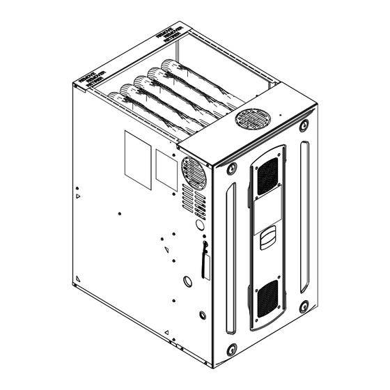
Page 14: Outline Drawing
Outline Drawing S8V2-SVX001-1A-EN... -
Page 15: Wiring Diagrams
THESE ARE CONFIGURABLE IN THE TECH APP. FLAME_ROLLOUT1 YL/48 YL/6 RD/51 Model Number Recovery RD/49 S8V2-C 24 Volt Operation ONLY FLAME_ROLLOUT2 YL/10 YL/50 Display Model Number RAF-1 S8V2A040M3PC* SEE NOTE #6 S8V2B060M4PC* YL/45 RD/18 VALVE S8V2B080M4PC* THERMAL_LIMIT PANEL LOOP S8V2C080M5PC* RAF-2 S8V2C100M5PC* YL/45 S8V2D120M5PC* S8V2A040M3PD*... -
Page 16: Airflow Tables
Airflow Tables Table 2. S8V2A040M3P Heating Airflow S8V2A040M3P Furnace Heating Airflow (CFM), Temp. Rise (°F), and Power (Watts) vs. External Static Pressure with Filter (iwc) 1st Stage Capacity = 21,000 2nd Stage Capacity = 32,200 Airflow External Static Pressure Target Heating Setting Airflow... - Page 17 A A i i r r f f l l o o w w T T a a b b l l e e s s Table 3. S8V2A040M3P Cooling Airflow (continued) S8V2A040M3P Furnace Cooling Airflow (CFM) and Power (Watts) vs. External Static Pressure with Filter (iwc) Outdoor EXTERNAL STATIC PRESSURE (IN.
- Page 18 A A i i r r f f l l o o w w T T a a b b l l e e s s Table 5. S8V2B060M4P Cooling Airflow S8V2B060M4P Furnace Cooling Airflow (CFM) and Power (Watts) vs. External Static Pressure with Filter (iwc) EXTERNAL STATIC PRESSURE (IN.
- Page 19 A A i i r r f f l l o o w w T T a a b b l l e e s s Table 6. S8V2B080M4P Heating Airflow S8V2B080M4P Furnace Heating Airflow (CFM), Temp. Rise (°F), and Power (Watts) vs. External Static Pressure with Filter (iwc) 1st Stage Capacity = 41,200 2nd Stage Capacity = 65,800...
- Page 20 A A i i r r f f l l o o w w T T a a b b l l e e s s Table 7. S8V2B080M4P Cooling Airflow (continued) S8V2B080M4P Furnace Cooling Airflow (CFM) and Power (Watts) vs. External Static Pressure with Filter (iwc) EXTERNAL STATIC PRESSURE (IN.
- Page 21 A A i i r r f f l l o o w w T T a a b b l l e e s s Table 9. S8V2C080M5P Cooling Airflow S8V2C080M5P Furnace Cooling Airflow (CFM) and Power (Watts) vs. External Static Pressure with Filter (iwc) EXTERNAL STATIC PRESSURE (IN.
- Page 22 A A i i r r f f l l o o w w T T a a b b l l e e s s Table 10. S8V2C100M5P Heating Airflow S8V2C100M5P Furnace Heating Airflow (CFM), Temp. Rise (°F), and Power (Watts) vs. External Static Pressure with Filter (iwc) 1st Stage Capacity = 52,300 2nd Stage Capacity = 81,200...
- Page 23 A A i i r r f f l l o o w w T T a a b b l l e e s s Table 11. S8V2C100M5P Cooling Airflow (continued) S8V2C100M5P Furnace Cooling Airflow (CFM) and Power (Watts) vs. External Static Pressure with Filter (iwc) EXTERNAL STATIC PRESSURE (IN.
- Page 24 A A i i r r f f l l o o w w T T a a b b l l e e s s Table 13. S8V2D120M5P Cooling Airflow S8V2D120M5P Furnace Cooling Airflow (CFM) and Power (Watts) vs. External Static Pressure with Filter (iwc) EXTERNAL STATIC PRESSURE (IN.
-
Page 25: Furnace General Installation
Furnace General Installation The following sections give general instructions for the The furnace may be placed horizontally in a crawl installation of the gas furnaces. space on a pad or other noncombustible material. Place blocks underneath to support the furnace and raise the unit for sufficient protection from moisture. -
Page 26: Gas Piping
F F u u r r n n a a c c e e G G e e n n e e r r a a l l I I n n s s t t a a l l l l a a t t i i o o n n Gas Piping Important: The furnace default is left side gas piping. - Page 27 F F u u r r n n a a c c e e G G e e n n e e r r a a l l I I n n s s t t a a l l l l a a t t i i o o n n Note: For ease of installation, optional accessory part PIP02095 is recommended for gas piping entering the right side of the furnace.
-
Page 28: Combustion And Input Check
F F u u r r n n a a c c e e G G e e n n e e r r a a l l I I n n s s t t a a l l l l a a t t i i o o n n Combustion and Input Check I I m m p p o o r r t t a a n n t t : : If local codes allow the use of flexible gas appliance connector, always use a new... -
Page 29: Gas Valve Adjustment
F F u u r r n n a a c c e e G G e e n n e e r r a a l l I I n n s s t t a a l l l l a a t t i i o o n n Gas Valve Adjustment Changes can be made by adjusting the manifold pressure, or changing White-Rodgers 36J... -
Page 30: High Altitude Derate
F F u u r r n n a a c c e e G G e e n n e e r r a a l l I I n n s s t t a a l l l l a a t t i i o o n n High Altitude Derate Input ratings (BTUH) of these Furnaces are based on sea level operation and should not be changed at elevations up to 2,000 ft. -
Page 31: General Venting
F F u u r r n n a a c c e e G G e e n n e e r r a a l l I I n n s s t t a a l l l l a a t t i i o o n n Table 14. - Page 32 F F u u r r n n a a c c e e G G e e n n e e r r a a l l I I n n s s t t a a l l l l a a t t i i o o n n EXTERNAL MASONRY CHIMNEY Venting of fan assisted appliances into external chimneys (one or more walls Gas Vent Termination...
-
Page 33: Air For Combustion And Ventilation
F F u u r r n n a a c c e e G G e e n n e e r r a a l l I I n n s s t t a a l l l l a a t t i i o o n n Air for Combustion and and ventilation requirements can be supplied from inside the building. - Page 34 F F u u r r n n a a c c e e G G e e n n e e r r a a l l I I n n s s t t a a l l l l a a t t i i o o n n CONFINED CONFINED SPACE AIR FROM OUTDOORS...
-
Page 35: Duct Connections
F F u u r r n n a a c c e e G G e e n n e e r r a a l l I I n n s s t t a a l l l l a a t t i i o o n n Duct Connections Air duct systems should be installed in accordance with standards for When the furnace is located in a utility room adjacent to the living... - Page 36 F F u u r r n n a a c c e e G G e e n n e e r r a a l l I I n n s s t t a a l l l l a a t t i i o o n n Table 15.
- Page 37 F F u u r r n n a a c c e e G G e e n n e e r r a a l l I I n n s s t t a a l l l l a a t t i i o o n n Horizontal Right and Downflow Furnace —...
- Page 38 F F u u r r n n a a c c e e G G e e n n e e r r a a l l I I n n s s t t a a l l l l a a t t i i o o n n R R e e t t u u r r n n D D u u c c t t C C o o n n n n e e c c t t i i o o n n s s Return Ducting General Guidelines •...
- Page 39 F F u u r r n n a a c c e e G G e e n n e e r r a a l l I I n n s s t t a a l l l l a a t t i i o o n n Upflow Furnace with Bottom and Side Returns Mounted on a Cabinet cutout when used with BAYLIFT 21”...
- Page 40 F F u u r r n n a a c c e e G G e e n n e e r r a a l l I I n n s s t t a a l l l l a a t t i i o o n n Downflow Furnace with Top Return Downflow Furnace with Top Return and Plenum Refer to...
-
Page 41: Return Air Filters
F F u u r r n n a a c c e e G G e e n n e e r r a a l l I I n n s s t t a a l l l l a a t t i i o o n n Return Air Filters TYPICAL AIR FILTER INSTALLATIONS Filters are not factory supplied for furnaces. - Page 42 F F u u r r n n a a c c e e G G e e n n e e r r a a l l I I n n s s t t a a l l l l a a t t i i o o n n When the furnace is installed in the horizontal right or left Figure 1.
-
Page 43: Electrical Connections
F F u u r r n n a a c c e e G G e e n n e e r r a a l l I I n n s s t t a a l l l l a a t t i i o o n n Electrical Connections Make wiring connections to the unit as indicated on enclosed wiring diagram. - Page 44 F F u u r r n n a a c c e e G G e e n n e e r r a a l l I I n n s s t t a a l l l l a a t t i i o o n n 1.
- Page 45 F F u u r r n n a a c c e e G G e e n n e e r r a a l l I I n n s s t t a a l l l l a a t t i i o o n n Table 16.
- Page 46 F F u u r r n n a a c c e e G G e e n n e e r r a a l l I I n n s s t t a a l l l l a a t t i i o o n n Table 18.
-
Page 47: Accessories
F F u u r r n n a a c c e e G G e e n n e e r r a a l l I I n n s s t t a a l l l l a a t t i i o o n n External Switches and Accessories When connecting a humidifier or electronic air cleaner to the furnace, use ACC1 for the air cleaner and ACC2 for the humidifier. -
Page 48: General Start-Up And Adjustment
General Start-up and Adjustment The following sections give instructions for the general start-up and adjustment of the gas furnaces. Preliminary Inspections With gas and electrical power "OFF", ensure: Turn knob on main gas valve within the unit to the "OFF" position. Turn the external gas valve to "ON". -
Page 49: Options
Furnace Combustion Air Exhaust Options Note: Default is left side for electric and gas connections. The following sections give instructions for the I I m m p p o o r r t t a a n n t t : : When looking at the different orientations, different furnace orientations and the options for the direction of the combustion air exhaust venting the exhaust combustion air. - Page 50 F F u u r r n n a a c c e e C C o o m m b b u u s s t t i i o o n n A A i i r r E E x x h h a a u u s s t t O O p p t t i i o o n n s s Table 21.
-
Page 51: Combustion Air Conversions
F F u u r r n n a a c c e e C C o o m m b b u u s s t t i i o o n n A A i i r r E E x x h h a a u u s s t t O O p p t t i i o o n n s s Combustion Air Conversions Pressure Switch locations Important: After deciding the orientation of the flue outlet, cut the... - Page 52 F F u u r r n n a a c c e e C C o o m m b b u u s s t t i i o o n n A A i i r r E E x x h h a a u u s s t t O O p p t t i i o o n n s s Horizontal right orientation with top venting Downflow orientation with left side venting Refer...
-
Page 53: Integrated Furnace Control Menu
3 mes. This confirms the faults have been cleared. Example Example Example S8V2A040M3 S8V2B060M4 S8V2B080M4 Model Number Model Number Model Number Recovery Digit Recovery S8V2A040M3PC Example Example S8V2B060M4PC seconds Enhanced Mode S8V2B080M4PC S8V2C080M5PC S8V2C100M5PC Cooling Off Delay S8V2D120M5PC S8V2A040M3PD Example... - Page 54 I I n n t t e e g g r r a a t t e e d d F F u u r r n n a a c c e e C C o o n n t t r r o o l l M M e e n n u u S8V2-C Run Test Mode Run Test Mode:...
-
Page 55: Belly Band Location
Belly Band Location Distance from belly band to the front face of motor for minimum vibration Furnace Model Dimension “A” (inches) A040 3.87 1.25 Blower housing and wheel removed from view for clarity. Furnace Model Dimension “A” (inches) B060 5.04 B080 5.04 1.25... -
Page 56: Codes
Integrated Furnace Control Display Codes Menu Options Orientation Active Alarm Menu Last 6 Faults (To clear – Hold Option button down for 5 seconds after entering the L6F menu) Code Release Number Model Number Recovery Cooling Off Delay (Seconds) Outdoor Tonnage Outdoor Unit Type (Single / Two Stage) Blower Constant Fan Airflow Multiplier % Cooling (CFM/Ton) -
Page 57: Fault Code Recovery
I I n n t t e e g g r r a a t t e e d d F F u u r r n n a a c c e e C C o o n n t t r r o o l l D D i i s s p p l l a a y y C C o o d d e e s s Redundant relay (HLO output) energized when it should not be e7.2 Low flame sense. - Page 58 I I n n t t e e g g r r a a t t e e d d F F u u r r n n a a c c e e C C o o n n t t r r o o l l D D i i s s p p l l a a y y C C o o d d e e s s IFC Component Layout BAYSENSC360 - Optional Kit for 24V Mode...
-
Page 59: Troubleshooting
Troubleshooting The following pages include troubleshoo ng flowcharts in reference for the 2 Stage S8V2* family of furnaces only. The informa on contained is for reference only and does not cover all scenarios or problems that may be encountered. ONLY qualified technicians should a empt to install, troubleshoot, or repair this appliance. - Page 60 T T r r o o u u b b l l e e s s h h o o o o t t i i n n g g GETTING STARTED Is 120 VAC Is the IFC Seven Is 120 VAC Is 120 VAC measured measured Segment LED on?
- Page 61 T T r r o o u u b b l l e e s s h h o o o o t t i i n n g g DEFINITION 2.1 Fault Code RETRY Lock Out = 6 unsuccessful tries for igni on within a single call for heat.
- Page 62 T T r r o o u u b b l l e e s s h h o o o o t t i i n n g g DEFINITION 2.2 Fault Code RECYCLE Lock Out = 10 recycles within a single call for heat.
- Page 63 T T r r o o u u b b l l e e s s h h o o o o t t i i n n g g DEFINITION Note #1 An error has occurred with the PS1, indica ng that the pressure 3.1 Fault Code switch is closed when it should be open.
- Page 64 T T r r o o u u b b l l e e s s h h o o o o t t i i n n g g DEFINITION 3.3 Fault Code An error has occurred with the PS2, indica ng that the pressure Note #1 switch is closed when it should be open.
- Page 65 T T r r o o u u b b l l e e s s h h o o o o t t i i n n g g 4.0 Fault Code Limit switches are safety devices Main Thermal Limit that will open when an abnormal high temperature has been sensed.
- Page 66 T T r r o o u u b b l l e e s s h h o o o o t t i i n n g g 4.1 Fault Code DEFINITION Limit switches are safety devices Open Reverse Air Flow Limit that will open when an abnormal high temperature has been sensed.
- Page 67 T T r r o o u u b b l l e e s s h h o o o o t t i i n n g g 4.2 Fault Code DEFINITION Limit switches are safety devices Roll-Out Limit that will open when an abnormal high temperature has been sensed.
- Page 68 T T r r o o u u b b l l e e s s h h o o o o t t i i n n g g DEFINITION 5.0 Fault Code Flame is sensed when it should not be sensed. Disconnect electrical power to furnace Turn off...
- Page 69 T T r r o o u u b b l l e e s s h h o o o o t t i i n n g g DEFINI Polarity Fault – Incoming high voltage 6.1 Fault Code wiring is reversed Connect volt meter to white incoming...
- Page 70 T T r r o o u u b b l l e e s s h h o o o o t t i i n n g g DEFINITION: Igniter Relay Fault – The control board has sensed 6.3 Fault Code that the igniter relay has stuck closed igniter Fault –...
- Page 71 T T r r o o u u b b l l e e s s h h o o o o t t i i n n g g DEFINITION: External Gas Valve 7.1 Fault Code Circuit Error (24 volts is present when it should not be present) Turn Comfort Control to “OFF”...
- Page 72 T T r r o o u u b b l l e e s s h h o o o o t t i i n n g g DEFINITION: 08 Fault Code The flame sense current is less than 0.5 micro-amp DC Make a call for 1 stage hea ng...
- Page 73 T T r r o o u u b b l l e e s s h h o o o o t t i i n n g g 11 Fault Code Defini on: The IFC has detected that internal gas valve relays have failed.
- Page 74 T T r r o o u u b b l l e e s s h h o o o o t t i i n n g g 13 Fault Code This fault is generated when the HP of the blower motor does not match the value that is programmed on the IFC Disconnect electrical...
- Page 75 T T r r o o u u b b l l e e s s h h o o o o t t i i n n g g DEFINITION: This fault is most likely due to intermi ent E17 Fault Code low voltage control wiring connec ons.
- Page 76 T T r r o o u u b b l l e e s s h h o o o o t t i i n n g g E23 Fault Code DEFINITION: The Combus on Control Micro on the IFC has incomplete menu data.
- Page 77 T T r r o o u u b b l l e e s s h h o o o o t t i i n n g g DEFINITION: This fault is generated when the Return Sta c pressure transducer (BAYFURNPTKT accessory) is out of bounds or has been enabled and the wiring harness has not been connected to the IFC.
- Page 78 T T r r o o u u b b l l e e s s h h o o o o t t i i n n g g DEFINITION: This fault is generated when the Supply temperature E28 Fault Code sensor is Open / Shorted or when the sensor has been enabled but not installed/plugged in.
- Page 79 T T r r o o u u b b l l e e s s h h o o o o t t i i n n g g THERMISTOR TABLE THERMISTOR THERMISTOR T deg F T deg C T deg F T deg C RESISTANCE...
-
Page 80: Sequence Of Operation
Sequence of Operation N N o o t t e e : : The seven-segment LED readout is based on N N o o t t e e : : There are two flame sense pads located on the thermostat input. A simultaneous call for W1 and IFC marked as “FP”. - Page 81 S S e e q q u u e e n n c c e e o o f f O O p p e e r r a a t t i i o o n n N N o o t t e e : : If PS2 does not close within the 45 second time, •...
-
Page 82: Periodic Servicing Requirements
Periodic Servicing Requirements 1. GENERAL INSPECTION – E E x x a a m m i i n n e e t t h h e e f f u u r r n n a a c c e e N N o o t t e e : : Be careful NOT to break igniter when removing i i n n s s t t a a l l l l a a t t i i o o n n a a n n n n u u a a l l l l y y f f o o r r t t h h e e f f o o l l l l o o w w i i n n g g i i t t e e m m s s : : burners. -
Page 83: Notices
Notices F F C C C C N N o o t t i i c c e e I I C C N N o o t t i i c c e e Contains FCC ID: WAP3025 Contains IC ID: 7922A-3025 This device complies with part 15 of the FCC Rules. - Page 84 About Trane and American Standard Heating and Air Conditioning Trane and American Standard create comfortable, energy efficient indoor environments for residential applications. For more information, please visit www.trane.com or www.americanstandardair.com. The manufacturer has a policy of continuous data improvement and it reserves the right to change design and specifications without notice. We are committed to using environmentally conscious print practices.
Need help?
Do you have a question about the S8V2A040M3PC and is the answer not in the manual?
Questions and answers
at what decibel range does thos operate