
Related Manuals for Liscarroll Engineering LE-200

Summary of Contents for Liscarroll Engineering LE-200
- Page 1 EST. 1973 Universal Tank Controller: LE-200 Installation and Operating Instructions for Installers and Service Engineers Simply Better . . . by Design...
- Page 2 Notes...
-
Page 3: Table Of Contents
37 - Default Parameters CAREL 38 - Technical Specifications 38 - Wiring Diagram 39 - How to use the Programming Key Appendix 1 - Main Wiring Diagram Appendix 2 - Card Wiring Diagram Appendix 3 - Wash Program -v- Tank Size LE-200... -
Page 4: Appliance Description
CLEANING mode The cleaning timer controls water intake by time. The LE-200 has the following built-in programs to cater for all tank sizes and to allow for varying on-farm conditions. (1) MAIN WASH ALKALINE: 3 Programs: 30 Minute, 50 Minute, 75 Minute... -
Page 5: Safety
The device is fitted with a resistance temperature sensor. The device must not be installed in potentially explosive atmospheres. The universal tank control type LE-200 fulfills the EC requirements for electromagnetic compatibility (EMC) and the Low Voltage Directive (LVD). The safety components meet the VDE regulations. LE-200... -
Page 6: Intended Use
Installation Installation of Housing It is essential not to install the device under the following conditions: • severe jolting or vibration • permanent contact with water • relative humidity of more than 90% • sharply fluctuating temperatures (condensation) • operation in an aggressive atmosphere (ammonia or sulphur fumes) - risk of oxidation •... -
Page 7: Fitting The Sensor
The mains voltage should not be switched on until all components including the sensor are connected. No appliances with current levels in excess of the maximum values indicated on the relays should be connected to the relay contacts Use contactors. Downstream contactors must be fitted with an RC protection circuit. LE-200... -
Page 8: Connection Diagram
Installation Connection diagram • Electrical connections must be as shown in the diagram below. • Use cable bushes. • Make sure that cables cannot chafe. • Observe relay current rating. • In all cases use contactors for pump and compressor. •... -
Page 9: Technical Data
KTY sensor Bush material 1.4301(V2A) Bush length 40 mm Bush diameter 6.0 mm +/- 0.1 Cable material Measurement range -10 .. 70° C Cable length Standard 2 metres Protection type IP 65 Sensors other than our standard type are available on request Some of the options are shown here. LE-200... -
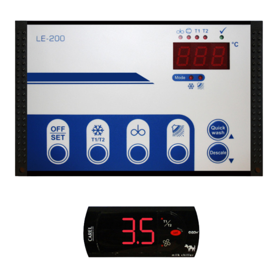
Page 10: Operating Levels
Extended cooling parameters Code: 567 Extended cleaning parameters Code: 0E5 I/O test parameters Operation of the LE-200 takes place at various levels: Working level: … for normal daily operation. • OFF mode = control unit switched off. • Start cooling mode. -
Page 11: Operation Of Working Level
COOLING mode (press 1 sec.) = Intermediate stirring SHORT in COOLING mode (press 3 sec.) = Intermediate stirring LONG See also section: ‘Intermediate stirring options’ . WASHING button in OFF mode = Start cleaning During the cleaning process = Special function when Commissioning/Service (See page 16) LE-200... -
Page 12: Meaning Of Leds
Operating of Working Levels Meaning of LEDs LED “AGITATOR” in all mode - Agitator is switched on LED “COMPRESSOR” Continuous: Compressor contactor is switched on Blinking: Minimum switch-off time (swing protection) is still active LED “T1” Target temperature ‘T1’ active LED “T2”... -
Page 13: Operating Modes
‘pause time’ set [C21], for the duration of the ‘after-stirring’ time [C20], in order to ensure an even temperature throughout the milk. If the milk temperature exceeds the selected target temperature by the set ‘differentials’ value [C10 or C11] the compressor and agitator automatically start again. LE-200... -
Page 14: Deep Cool
Operating of Working Levels Deep cool Press the ‘COOLING’ button twice activates the T2, (Deep cool, function: default 2°C) Stirring in cooling mode = INTERMEDIATE STIRRING Briefly press ‘AGITATOR’ in cooling mode: A short intermediate stirring period [duration = C23] is triggered. Press ‘AGITATOR’ in cooling mode for around 5 seconds: A long intermediate stirring period [duration = C24] is triggered. -
Page 15: Cleaning Program Description
• cleaning stops, • the display alternately shows ‘AbL’ and the current temperature, • for the time [n70] drain valve is opened (can be stopped by repeated pressing of the Off-button). • control switches into the OFF-mode. LE-200... -
Page 16: Power Failure During The Cleaning Process
Cleaning Program Description Power failure during After return of voltage in case of a power failure: the cleaning process • display shows the current temperature • drain valve is opened for the time [n70] • control continues the cleaning at the start of the cleaning stage in which the interruption happened •... -
Page 17: Adjusting Of Parameters In General
• Press the ‘SET’ button: the parameter value is displayed. Change parameter value: Saving the changed parameters and switching back to the working level: (possible from any parameter) • Press UP and DOWN buttons simultaneously for approx. 5 seconds. The device switches to the OFF mode. LE-200... -
Page 18: Adjustment Of Cleaning Step Times
Adjustment of Cleaning Step Times Step Times CODE Code: 111 Main Wash: ‘n’ parameters Code: 222 Descale Wash: ‘d’ parameters Code: 333 Quick Wash: ‘u’ parameters The step times as set in Parameters r1, r2 and r3 are fixed and cannot be altered. USER DEFINED PROGRAM TIMES But should it be necessary to make adjustments this can be done selecting Parameter ‘r4’... - Page 19 Cooling Parameters Code 212: GENERAL COOLING PARAMETERS C Parameter Description Range LE-200 Default Temperature Settings Target temperature T1 – 12,0 °C Target temperature T2 (Deep cool) – 12,0 °C Differential for T1 – 2,0 °C Differential for T2 (Deep cool) –...
-
Page 20: Cleaning Parameters
Cleaning Parameters Code 567 CLEANING PARAMETERS / configuration (r-level) Parameter Description Range LE-200 Default Setting Wash Program Times Time selection main wash 1: 75 min 2: 50 min 1...3 3: 30 min Time selection descale wash 1: 75 min 2: 50 min 1...3... -
Page 21: Cleaning Parameters Descale
1,25 125 2,09 3,13 1,00 100 1,67 2,50 Code 222: CLEANING PARAMETERS DESCALE (d-level) LE-200 Descale Wash (Alkaline & Acid) K6 or 7 33 Mins 50 Mins 75 Mins Step Programs Stage H.SV C.SV PUMP AGIT D.V ALK P-ACID ACID... - Page 22 Cleaning and Test Parameters Code 333: CLEANING PARAMETERS QUICK WASH (u-level) LE-200 Quick Wash K6 or 7 8 Mins 12 Mins 18 Mins Step Programs Stage H.SV C.SV PUMP AGIT D.V ALK P-ACID ACID Sec Min Stage/Step 1,50 135 2,25...
-
Page 23: Fault Indication On The Display
Please contact the manufacturer. must be replaced or repaired. Parameter [C91] ‘Actual value correction’ must then be adjusted at Programming level. Memory fault Automatic factory reset after update The controller was reset to factory settings after a software update. LE-200... -
Page 24: Water And Detergent Usage - 30 Mins
WATER AND DETERGENT USAGE Eco Wash 5 Cycle: 30 Minutes Water Intake – Time 3.08 Flow l/min Litres Gallons 21.6 24.7 27.8 30.8 33.9 Water Intake – Time 3.08 Flow l/min Litres Gallons 21.6 24.7 27.8 30.8 33.9 PP Time (mins) 4.58 Detergent Required Actual Vol of Detergent (Etatron Pump) Water Intake –... -
Page 25: Water And Detergent Usage - 50 Mins
Water Intake – Time 5.14 0.15% 0.30% 0.40% 0.15% 0.30% 0.40% Flow l/min Litres Gallons 7.92 9.06 10.19 11.32 12.45 Time (Mins) Total Water Consumption I/min 7.64 1.67 Water Flow 1/min COLD 1039 1283 1681 1772 Default Setting Alkaline Pump Acid Pump LE-200... -
Page 26: Water And Detergent Usage - 75 Mins
WATER AND DETERGENT USAGE Eco Wash 5 Cycle: 75 Minutes Water Intake – Time 7.7 Flow l/min Litres Gallons 11.9 13.6 15.3 17.0 18.7 Water Intake – Time 7.71 Flow l/min Litres Gallons 11.9 13.6 15.3 17.0 PP Time (mins) 11.46 18.7 Detergent Required Actual Vol of Detergent (Etatron Pump) - Page 27 Gallons 7.07 8.08 9.09 10.10 11.10 Water Intake – Time 4 Flow l/min Litres Gallons 6.17 7.05 7.93 8.81 9.69 Time (Mins) Total Water Consumption I/min 4.58 Water Flow 1/min COLD 1008 1063 Default Setting Alkaline Pump Acid Pump LE-200...
- Page 28 WATER AND DETERGENT USAGE DESCALE (Alkaline & Acid) Wash 5 Cycle: 50 Minutes Water Intake – Time 4.7 Flow l/min Litres Gallons 10.3 PP Time (mins) 6.9 11.3 Detergent Required Actual Vol of Detergent (Etatron Pump) Water Intake – Time 6.9 0.50% 0.80% 1.00% 0.50% 0.80% 1.00% Flow l/min Litres...
- Page 29 25.2 1146 1215 Water Intake – Time 7 Flow l/min Litres Gallons 10.8 12.3 13.9 15.4 17.0 Time (Mins) Total Water Consumption I/min 10.42 Water Flow 1/min COLD 1125 1417 1750 2292 2417 Default Setting Alkaline Pump Acid Pump LE-200...
-
Page 30: Other Information
Other Information Function The universal tank control LE-200 has a function allowing the agitator to be “Intermediate stirring” switched on manually in cooling mode. This can be done is different ways. Regardless of the chosen option the corresponding LED always indicates when the agitator is operating. -
Page 31: Procedure Following Power Failure
If “EEP” appears again on the display after the factory reset and after another OFF and ON-switching, the control is irreparably defective. Memory fault Automatic factory reset after update The controller was reset to factory settings after a software update. LE-200... -
Page 32: 33 - General Measures When Using Electronic Control Systems
Other Information General measures So that even complicated regulatory tasks can be presented to the user in a when using electronic manner which is clear and simple and ensures high measurement accuracy, today’s electronic control systems make increasing use of microprocessors. However, control systems the benefits of these systems are countered by the disadvantage that increased measurement accuracy is accompanied by sensitivity to interference. - Page 33 The suggestions made represent only a few of the possible ways of protecting a microprocessor-controlled regulator system from interference. The suggested measures have the advantage that they will increase the lifetime of the devices as lower induction voltages (reduced spark formation) will also reduce contact burn. LE-200...
-
Page 34: Backup Cooling Functions
Backup Cooling Functions LE-200 Universal Tank Controller Backup Cooling Function The LE-200 Universal Tank Controller has the added feature of a thermostatically controlled backup cooling function. To activate this function simply turn the switch located on the right-hand side of the control panel from “Normal”... -
Page 35: Carel Easy Milk Chiller
SET for 3 s: to exit without saving the changed values do not press any button for at least 60 s; Parameter Folders / PROBE r CONTROL c COMPRESSOR A ALARM P AGITATOR H OTHER SETTINGS Parameter Types F Frequent C Configuration LE-200... - Page 36 CAREL Easy Milk Chiller Default Parameters CAREL (for back-up cooling) TABLE OF PARAMETERS PARAMETER TYPE MIN. MAX. DEF. U.M. PASSWORD Default PROBE PARAMETERS Measurement stability Select probe/input displayed (1= probe 1, 2= probe 2, 3= probe 3) Select °C / °F ( 0 = °C; 1 = °F) Disable decimal point Probe 1 calibration -12.7...
- Page 37 1= keypad enabled 2= keypad enabled except for change setpoint1/setpoint 2 with SET Disable buzzer 0= buzzer enabled (ON); 1= buzzer disabled (OFF) Key ID code from supervisor Select Easy Set according to the model, see manual (see note) LE-200...
-
Page 38: Technical Specifications
CAREL Easy Milk Chiller Technical Specifications Power Supply (*) 230 Vac +10/-15% 50/60 Hz; 115 Vac +10/-15% 50/60 Hz 12 Vac +10/15% 50/60 Hz class 2; 12 Vdc +10/-20% class 2; Rated Power 3.5 VA Inputs (*) NTC or PTC probes 1 or 3 inputs Digital input as alternative to third probe Relay outputs (*) 2 HP relay UL: 12 A Res. -
Page 39: How To Use The Programming Key
Programming Key Programming keys PSOPZKEY00/A0 The programming keys are used to copy the complete set of parameters relating to the LE-200 back-up cooling solution parameters. The keys must be connected to the connector (4 pin AMP) fitted on the compatible controllers, and work even without switching the controller on. Three functions are available, and are selected by using the two supplied dipswitches;... -
Page 40: Appendix 1 Main Wiring Diagram
Appendix 1 Main Wiring Diagram... -
Page 41: Appendix 2 Card Wiring Diagram
Appendix 2 Card Wiring Diagram LE-200... -
Page 42: Appendix 3 Wash Program -V- Tank Size
Appendix 3 Wash Program -v- Tank Size FALL 1:50 Tank Size Depth Surface Min H.W Min H.W Flow Program Req Drain Model Litres litres 0.5%*Vol l/M² * Actual 40l/m SV+P total 4,500 EDX1000 15.92 22.5 41.2 5,000 EDX1100 17.21 25.0 41.2 5,800 EDX1300... - Page 43 Notes LE-200...
- Page 44 EST. 1973 Liscarroll Engineering Limited Liscarroll, Mallow, Co. Cork, Ireland. Tel: +353 (0)22 48200 Fax: +353 (0)22 48386 e-mail: info@liscarrollengineering.ie web: www.liscarrollengineering.ie Simply Better . . . by Design...
Need help?
Do you have a question about the LE-200 and is the answer not in the manual?
Questions and answers