
Related Manuals for Liscarroll Engineering LE-300

Summary of Contents for Liscarroll Engineering LE-300
- Page 1 EST. 1973 Simply Better . . . by Design Universal Tank Controller: LE-300 Installation and Operating Instructions for Installers and Service Engineers...
-
Page 2: Table Of Contents
Contents Introduction 1.1 Information about this operating instructions 1.2 Limitation of liability 1.3 Warning notices in these operating instructions 1.4 Device description 1.5 Type designation 1.6 Item supplied 1.7 Dimensions 1.8 Sensor dimensions and technical data 1.9 Technical data of control unit 2. - Page 3 8.12 Cleaning parameters / step times (u-level) – Quick wash 8.13 Setting of parameters 86-87 8.14 Setting of parameters 88-90 8.15 Setting of parameters 91-92 8.16 Setting of parameters 8.17 A Parameters 94-100 8.18 Setting of parameters 101-103 8.19 Setting of parameters 8.20 A Parameters LE-300...
- Page 4 9. Other information – General 9.1 Butterfly valve (manual or pneumatic) 9.2 Safety switch for manual butterfly valve 9.3 Sensor correction procedure 9.4 Function second temperature sensor 9.5 Test functions 9.5.1 Test alarm F99 9.5.2 Function test “Do-Not-Load LED” and “external alarm light” 9.6 Procedure following power failure 108-109 9.7 Power pack or operation via external power supply...
-
Page 5: Information About This Operating Instructions
1.1 Information about this operating instructions These operating instructions are intended for the use by Installation Engineers, installers or service technicians of the LE-300 universal tank control. This manual contains all necessary suggestions, Information, recommendations and advice for the safe and proper installation and commissioning of the tank control. -
Page 6: Limitation Of Liability
1.2 Limitation of liability The proper function of the LE-300 depends on many external factors WARNING on which the manufacturer has no influence. The manufacturer accepts no liability for any damages on the milk cooling tank, the connected components or the milk. The integrated tank monitor supports only... -
Page 7: Device Description
The manufacturer cannot be held liable for errors and may at any time make changes serving technical progress. All rights reserved. 1.4 Device description The LE-300 is an universal tank control unit that combines various basic functions in one unit a milk cooling thermostat... -
Page 8: Item Supplied
1.6 Item supplied - Controller LE-300 - Holder - Rubber seal - Sensor TF1A-2 - Fixing screws - Any optional accessories ordered. 1.7 Dimensions 1.8 Sensor dimensions and technical data Sensor element KTY 81-210 Bush material 1.4301 (V2A) Bush length... -
Page 9: Technical Data Of Control Unit
Overvoltage category III, pollution degree I Environment specifications: - Operation temperature 0° .. +50°C - Storage temperature -20° .. +70°C - max. humidity 75% (no dew) 75% (no dew) Technical data subject to change. * via I/O expansion module ESIO-001 LE-300... -
Page 10: Safety
IMPORTANT NOTICE ON LIABILITY NOTICE The faultless function of the LE-300 depends on many external factors, which the manufacturer has no influence on. The manufacturer assumes no liability for damage to the milk cooling tank, the connected components or the milk. -
Page 11: Intended Use
Please read carefully before installation and before any work on or with the regulator! Universal tank controllers LE-300 are designed to control heating systems, condensing units, alarms, fans, etc. in milk cooling tanks as well as to monitor milk quality. Furthermore, connected milking robots can be controlled. Any other use of the device is permitted only with prior written permission from the manufacturer. -
Page 12: Wiring, Screening, Earthing
Important note concerning the external fuse NOTICE - The transformer, which is installed in the LE-300, has a two-chamber safety winding, which is only short-circuit-proof due to the built-in thermal protection. If the temperature exceeds 145 ° C, there is a risk of damage! -
Page 13: Installation
- Place the seal carefully in the groove. Ensure it is not twisted. - Insert the housing from the front through the switchboard cut-out. - Attach the holding frame in the rear position as shown by the picture. - Fasten the housing by using the screws provided. LE-300... -
Page 14: Fitting The Sensor
(not even within the switchbox). Temperature range sensor cable -10°C .. +70°C The LE-300 has been designed for connection to various types of sensor (see technical data). It can function properly only if one of those sensor types is installed and the parameters are correctly set. -
Page 15: Electrical Connection
DIN VDE 0100 “Erection of power installations with rated voltages below 1000” or the relevant national regulations. Furthermore, all connections must comply with the relevant VDE regulations or corresponding national regulations. LE-300... -
Page 16: Wiring
4.3 Wiring (continued) - Within the two relay groups (K3 to K6) and (K9 to K12), the respective relays are connected with each other on one side. They connect the respective volt-age which has been connected at the feed point (terminals 8 and 17) to the load. -
Page 17: Wiring The Digital Inputs
4.6 Connection robot(optional) If the LE-300 and the robot have a separate power supply, the robot can still be stopped (by corresponding connection) in the event of power failure. Robot requires an active signal to stop (high-active) -
Page 18: Connection Of External Pressure Sensor (Optional)
4.7 Connection of external presure sensor (optional) Terminals 27 | 28 | 29 must be used only for the connection of an external Internal power supply pressure sensor. See section 10.5 via terminal 27 12 V +/- 3 V - max. 40 mA NOTICE If the sensor cannot be powered by internal power supply:... -
Page 19: Operation
5. Operation 5.1 Function overview The LE-300 is a universal tank control unit which combines all the basic functions in one device: - milk cooling control - comprehensive cleaning control - an extended robot interface - an extended tank monitor All basic functions can be selected and operated from the working level. -
Page 20: Continuous Stirring Mode
(heater, pump, detergent injection) can be set separately. The automatic switchover from acidic to alkaline detergent is also adjustable. The LE-300 controls the different processes and times fully automatically. Following a power failure the control unit will restart in the mode it was in before. -
Page 21: The Configuration Software Konsoft
Despite all care, we point out that the use of the free PC-Software is at your own risk. WELBA does not accept any liability for damages or loss of data resulting from the installation or use of the Software. LE-300... -
Page 22: Guideline For The Initial Installation / Parameterization
Step 9 Assign occurrences to the various alarms in the F-parameters (alarm horn, LED-display, SMS-message, etc.) TIPP For the parameterization and the commissioning of the LE-300 use the free Soft-ware “Welba KONSOFT”. Advantages: - Fast and comfortable parameterization of the LE-300. -
Page 23: Setting The Date And Time
For data evaluation, the Software Konsoft uses the entered date of the NOTICE LE-300. If date and time are not entered correctly, the evaluation is also incorrect! Now the control unit’s parameters must be properly set in line with the features of your system. -
Page 24: Operation In Levels
5.5 Operation in levels The working level is used for operation and control in everyday operation. The LE-300 is parameterised in 12 different parameter levels. The subordinate parameter levels are only entered after entering a code in order to avoid inadvertent adjustment of the parameters. -
Page 25: Operating Levels Explanation
Determination / Parameterisation of the hardware configuration Level 11 Alarm configuration - (F parameter) Here an individual behaviour can be assigned for each fault. Testing Level 12 I/O test parameters - (o parameter) Is intended for commissioning the control system. LE-300... -
Page 26: Operation Of Working Level
5.6 Operation of working level The working level is used for operation and control in everyday operation: - OFF mode = switch off the control (Stand-by) - Start cooling mode - Start continuous stirring - Start cleaning mode - Robot operation - Milk removal via the butterfly valve - Observe tank monitor 5.6.1 Button functions... - Page 27 5 seconds = Test of the red alarm-LED ROBOT STOP button (if parameterised) Starts or stops both the robot and the cooling mode as well. PNEUMATIC OUTLET VALVE button (if parameterised) Opens / closes the pneumatic outlet valve. LE-300...
-
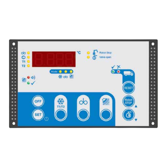
Page 28: Meaning Of The Led's
5.6 Operation of working level 5.6.2 Meaning of the LED‘s LEDs in cooling mode LED AGITATOR during cooling mode Agitator is switched on Robot Stop Valve open Mode LED COMPRESSOR permanently on Compressor contactor is switched on Robot Stop Valve open Compressor contactor is switched off RESET flashing slowly... - Page 29 - has already been acknowledged everything ok - milk can be loaded. Robot LED (blue) Data STOP RESET Flashing Tank monitor data are stored on the USB stick. 5 sec. permanent, Saving finished, stick can be removed. then off Robot STOP LE-300...
-
Page 30: Operation Modes
5.6 Operation of working level 5.6.3 Operation modes OFF mode The current time is displayed. (see also section 5.4) The control unit is on stand-by - All mode LEDs are out. - All output relays are deactivated (Exceptions: robot, butterfly valve and tank monitor alarms may be active) CAUTION: The control unit is live even when switched off! Cooling mode... - Page 31 A “short intermediate stirring” is triggered [duration = c23]. The indication “Sho” is displayed. - In cooling mode, press the AGITATOR button for 5 seconds: A “long intermediate agitating” is triggered [duration = c24]. The indication “Lon” is displayed. LE-300...
- Page 32 5.6 Operation of working level 5.6.3 Operation modes Continuous stirring mode if parameter [c25] = ‘0’ - Press the “AGITATOR” button: (from OFF mode) Switches on continuous stirring mode (revolving bar in the display). - Press “OFF” button: Switches off continuous stirring mode. if parameter [c25] >...
- Page 33 With the start / stop of the robot, the cooling mode of the milk tank is simultaneously started / stopped. - Hold down the ROBOT STOP button for approx. 3 seconds: robot operation is either enabled or stopped (Toggle function) The current switching status is indicated by LED. Robot Stop Valve open LE-300 RESET...
- Page 34 5.6 Operation of working level Robot Stop 5.6.3 Operation modes Valve open Milk collection Complete emptying of tank into collection tanker - Ensure that the green LED of the tank monitor indicator is lit - Press the OFF button - To stir the milk for a short period: briefly press the AGITATOR button. After the desired stirring time, stop the agitator by pressing the OFF button.
-
Page 35: Cleaning
- Fault code is displayed and must be acknowledged. Robot Stop Valve open NOTICE: The drain time [n100] can be stopped by pressing the OFF button. See also section 7.5.3 Reset / acknowledge the fault messages: - Press the RESET button for approx. 4 seconds. LE-300 RESET... -
Page 36: Power Failure During Cleaning
6.1 Abort of the cleaning 6.1.4 Power failure during cleaning - After the power returns after a power failure: - the display shows the current temperature alternating with ‘ABL’, - the drain valve is opened for the time [n100], - the control continues the cleaning at the start of the rinse cycle in which the interruption occurred. - Page 37 (r5 = 0). If automatic descaling is activated, the descaling button has no function. Settings for security elements r10-r12 See LE-300 manual Drain valve settings Switching direction drain valve 1 0…1 (0 = normally closed, 1 = normally opened) Switching direction drain valve 2 0…1...
- Page 38 6.2 Cleaning parameters / configuration (r-level) 6.2.1 Code C567 Parameter Description Range Default Level monitoring at the end of the wash cycle (F45) 0: disabled 1: Level 1 monitoring only after the last wash cycle. Abort, activates alarm message F45 and alarm relay 2: Level 1 monitoring after each wash cycle.
-
Page 39: Cleaning Parameters / Step Times (N-Level) - Eco Main Wash
Final rinse Water intake 0…999 sek Circulation with additional water intake + P-ACID 0…999 sek Circulation with additional water intake 0…999 sek Rinsing out 0…999 sek Drain off water 0…999 sek n100 Drain off water when cleaning is canceled 0…999 LE-300... -
Page 40: Cleaning Parameters / Step Times (D-Level) - Descale Wash
6.4 Cleaning parameters / step times (d-level) – Descale wash This time is used if r4 = 1 6.4.1 Code for d is 0222 Parameter Program step Description Range Default Pre rinse Water intake 0…999 sek Circulation with additional water intake 0…999 sek Rinsing out 0…999 sek... -
Page 41: Cleaning Parameters / Step Times (U-Level) - Quick Wash
Final rinse Water intake 0…999 sek Circulation with additional water intake + P-ACID 0…999 sek Circulation with additional water intake 0…999 sek Rinsing out 0…999 sek Drain off water 0…999 sek u100 Drain off water when cleaning is canceled 0…999 LE-300... -
Page 42: Cleaning Parameters
6.6 Cleaning parameters 6.6.1 Code 0111: CLEANING PARAMETERS MAIN WASH (n-level) LE-200 ECO Main Wash K6 or 7 30 Mins 50 Mins 75 Mins Step Programs Stage H.SV C.SV PUMP AGIT D.V ALK P-ACID ACID Sec Min Stage/Step 120 2,00 200 3,34 5,00 1,25... -
Page 43: Cleaning Parameters
The SET button can be used to check the switching status of 0 = input not connected the digital inputs. 1 = input connected No values can be entered here. 0 = input not connected 1 = input connected LE-300... -
Page 44: Water And Detergent Usage Eco Wash 5 Cycle: 30 Minutes
Water and Detergent Usage Eco Wash 5 Cycle: 30 Minutes Water Intake – Time 3.08 Flow l/min Litres Gallons 21.6 24.7 27.8 30.8 33.9 Water Intake – Time 3.08 Flow l/min Litres Gallons 21.6 24.7 27.8 30.8 33.9 PP Time (mins) 4.58 Detergent Required Actual Vol of Detergent (Etatron Pump) Water Intake –... -
Page 45: Water And Detergent Usage Eco Wash 5 Cycle: 50 Minutes
Water Intake – Time 5.14 0.15% 0.30% 0.40% 0.15% 0.30% 0.40% Flow l/min Litres Gallons 7.92 9.06 10.19 11.32 12.45 Time (Mins) Total Water Consumption I/min 7.64 1.67 Water Flow 1/min COLD 1039 1283 1681 1772 Default Setting Alkaline Pump Acid Pump LE-300... -
Page 46: Water And Detergent Usage Eco Wash 5 Cycle: 75 Minutes
6.10 Water and Detergent Usage Eco Wash 5 Cycle: 75 Minutes Water Intake – Time 7.7 Flow l/min Litres Gallons 11.9 13.6 15.3 17.0 18.7 Water Intake – Time 7.71 Flow l/min Litres Gallons 11.9 13.6 15.3 17.0 PP Time (mins) 11.46 18.7 Detergent Required Actual Vol of Detergent (Etatron Pump) -
Page 47: Water And Detergent Usage Descale Wash 5 Cycle: 33 Minutes
Gallons 7.07 8.08 9.09 10.10 11.10 Water Intake – Time 4 Flow l/min Litres Gallons 6.17 7.05 7.93 8.81 9.69 Time (Mins) Total Water Consumption I/min 4.58 Water Flow 1/min COLD 1008 1063 Default Setting Alkaline Pump Acid Pump LE-300... -
Page 48: Water And Detergent Usage Descale Wash 5 Cycle: 50 Minutes
6.12 Water and Detergent Usage DESCALE (Alkaline & Acid) Wash 5 Cycle: 50 Minutes Water Intake – Time 4.7 Flow l/min Litres Gallons 10.3 PP Time (mins) 6.9 11.3 Detergent Required Actual Vol of Detergent (Etatron Pump) Water Intake – Time 6.9 0.50% 0.80% 1.00%... -
Page 49: Water And Detergent Usage Descale Wash 5 Cycle: 75 Minutes
25.2 1146 1215 Water Intake – Time 7 Flow l/min Litres Gallons 10.8 12.3 13.9 15.4 17.0 Time (Mins) Total Water Consumption I/min 10.42 Water Flow 1/min COLD 1125 1417 1750 2292 2417 Default Setting Alkaline Pump Acid Pump LE-300... -
Page 50: Tank Monitor And General Fault Handling
“A” parameters (see section 8.11) must be Valve open assigned to a relay or the SMS function must be activated. The tank monitor of the LE-300 has the following alarm types: Critical tank monitor alarms (red LED + fault code in the display) During cooling: - min. - Page 51 If several alarms are present, the reset button must be pressed several times. See section 7.3 (Turns off when cleaning cycle runs for at least 10 minutes ...) 888 8 F 3 4 System alarm Is displayed as a blinking display code only. LE-300...
-
Page 52: Tank Monitor: Milk Removal Yes Or No
No alarm – Milk may be drawn off. Green = on = off - The driver goes to the LE-300 and checks the tank monitor. Robot Stop If the green LED is on, milk may be drawn off. RESET Valve open Once the milk has been taken, the driver starts the cleaning process. - Page 53 Critical Alarm RESET = on - The driver goes to the LE-300 and checks the tank monitor. The red LED is lit or flashing, an error code blinks in the display and, Robot depending on the circumstances, a horn may sound.
-
Page 54: Tank Monitor: Handling Multiple Faults
Robot Stop 7.3 Tank monitor: Handling multiple faults Valve open For every alarm - whether informative (green) or critical (red) – an error code blinks in the display. If several faults occur simultaneously, the code for the most recently occurring fault blinks in the display. -
Page 55: Listing Fault Codes And Their Description
“No stirring” time exceeded Alarm functions only if optional “Welba agitator monitor” is installed and parameters set [A71]. Alarm is triggered if, after the previous stirring, more than the number of minutes set in [H41] have passed without the agitator restarting. LE-300... -
Page 56: Informative Tank Monitor Alarms (Green)
Robot Stop Valve open 7.5.2 Informative tank monitor alarms (green) Cooling time exceeded for first milking Alarm is triggered if the temperature set in parameter [h20] is not reached within the time set in parameter [h21]. The time starts when cooling of the first milking starts. -
Page 57: System Alarms - Cleaning
After the cycle has ended, the controller switches to the OFF mode or, with the “Autostart cooling” parameterized, to the cooling mode. A code in the display indicates which error has occurred. This must be acknowledged with the reset button. LE-300... - Page 58 Safety switch for butterfly valve (only if [r10] = 2) washing stops outlet valve is opened for time [n100] (during the emptying phase the display alternates between F40 and AbL) the red LED “FAULT” then flashes, with error code F40 During washing the digital input for the tank outlet safety switch [r10] was triggered.
- Page 59 Possible cause of fault: Heater faulty Pressure switch has triggered Water circuit damaged / interrupted Excess temperature monitor for heater washing completed fault is shown on the display During washing the heater’s dry-running protection has triggered (if set in [r39]). LE-300...
-
Page 60: System Alarms - Cooling
7.5.4 System alarms - cooling Tank overflow protection Fault is displayed, when the maximum filling quantity of the tank has been achieved. Water in tank during cooling In cooling mode, water has been detected in the washing line through one of the level inputs. Possible cause of fault: one of the water valves open Parameters set in [P40] to determine whether only a fault report blinks... -
Page 61: System Alarms - External Sensors
Error is displayed when the power module ESVAW-003 (if available) detects a phase error. Depending on the parameterization of the parameter [A85], the cleaning is aborted in the event of a phase error. 7.5.7 Test alarm Test alarm (see section 9.5) LE-300... -
Page 62: Setting Of Parameters
8.1 Change and save parameter values The working level is used for operation and control in everyday operation. The LE-300 is parameterised in 12 different parameter levels. The subordinate parameter levels are only entered after entering a code in order to avoid inadvertent adjustment of the parameters. - Page 63 - the display shows the current time. Return WITHOUT saving the values: - Press the OFF button – or - If no button is pressed for 60 seconds: The controller automatically returns to the OFF mode. All changes are lost. LE-300...
-
Page 64: General Cooling Parameters (C-Level)
8.2 General cooling parameters (C-level) 8.2.1 Code C212 Parameter Description Range Default Temperature setting Target temperature T1 2,0 – 12,0 °C Target temperature T2 2,0 – 12,0 °C Hysteresis for target temperature T1 0,1 – 2,0 °C Hysteresis for target temperature T2 0,1 –... -
Page 65: Level "General Cooling Parameters" (C Parameters)
APPROX. 3 SECONDS during a cooling pause. Maximum continuous stirring period 0 .. 999 min. in mode ‚continuous stirring‘ Setting of maximum continuous stirring period. 0: indefinite stirring (to end, the OFF button must be pressed) 1..999: max. stirring period in minutes LE-300... - Page 66 8.3 Level “General cooling parameters” (c parameters) continued 8.3.1 Code C212 (continued) Sensor correction adjustment (see section 9.3) Range Default Display actual temperature sensor 1 Sensor correction sensor 1 -10 .. 10 K A correction can be applied to the value measured by the sensor.
-
Page 67: Level "Extended Cooling Parameters" (P Parameters)
8.4 Level “Extended cooling parameters” (P parameters) The working level is used for operation and control in everyday operation. The LE-300 is parameterised in 12 different parameter levels. The subordinate parameter levels are only entered after entering a code in order to avoid inadvertent adjustment of the parameters. - Page 68 8.4 Level “Extended cooling parameters” (P parameters) EMERGENCY COOLING, behaviour on sensor failure Range Default Manual start of compressor for x min. 0 .. 60 min. in case of sensor failure. Function see 10.3 Compressor protection when filling from below Range Default Compressor switch-on delay / pre-agitating...
- Page 69 (briefly). The maximum open time can be limited in [P33]. Max. open time for butterfly valve For drawing off 0 .. 60 sec. milk manually (hidden if A40 = 0 or 1 ) 0: no time limit on valve being open 1 to 60: seconds LE-300...
- Page 70 8.4 Level “Extended cooling parameters” (P parameters) continued Agitator settings Range Default Note on [P34] - Selection 2: Function 34 must be assigned to one of the digital inputs [A21..A33]. Lock the butterfly valve in OFF mode, if robots have 0 ..
- Page 71 3: In case of activated litre recording [A54]: Achievement of litres [P43] entered, triggers alarm. 4: Detection at level input 2 triggers alarm. Maximum filling quantity in litre 0 .. 500 input in hectolitres (=100 l) 0...500 (is equivalent to 0 to 50.000 litres) LE-300...
- Page 72 8.4 Level “Extended cooling parameters” (P parameters) continued Milk-volume-dependent cooling start delay Range Default (Cooling power reduction in case of robot operation) Capacity of the milk pump in litres / minute 1,0 .. 99,9 30,0 Is needed to calculate the milk quantity in the tank from the measured pump running time.
- Page 73 [P61] = 4 or 5 1 .. 100 Timeout delay via milk pump 1..999 min. only if [P61] = 4 or 5 Safety function: In the absence of milk pump impulses (for example, wire breakage), cooling is started after [P67] has elapsed. LE-300...
-
Page 74: Level "Extended Cooling Parameters" (P Parameters)
8.5 Level “Extended cooling parameters” (P parameters) Compressor settings Range Default Compressor mode continuous pulse operation 0 .. 1 Here can be activated that the compressor works in continuous Robot Stop pulse operation (reduction of the cooling performance) Valve open (after delay of cooling start it uses the times of P63, P64) 0: deactivated 1: activated... - Page 75 Duration until switch-back to T1 [P80] = 2 or 3 1 .. 999 min. Time 1 for automatic switchover to T2 see also [P80] 00:00 .. 23:59 4:00 Time 2 for automatic switchover to T2 see also [P80] 00:00 .. 23:59 16:00 LE-300...
- Page 76 8.5 Level “Extended cooling parameters” (P parameters) continued Freezing protection by low pressure monitoring Range Default Explanations see also section 10.8 Selection of sensor type 0 .. 2 Pressure detection via analogue input. Is only active when one of the analog inputs [A54, A56 or A57] =>...
- Page 77 Fault message high pressure (F81) 0 .. 2 0: deactivated 1*: high-active, signal at input triggers alarm 2*: low-active, no signal at the input triggers an alarm NOTE: Observe function assignment [A21 - A28]! * Note function assignment [A21..A33]! LE-300...
-
Page 78: Adjustment Of Cleaning Step Times
8.6 Adjustment of Cleaning Step Times Step Times CODE Code: 0111 Main Wash: ‘n’ parameters Code: 0222 Descale Wash: ‘d’ parameters Code: 0333 Quick Wash: ‘u’ parameters The step times as set in Parameters r1, r2 and r3 are fixed and cannot be al- tered. -
Page 79: Setting Of Parameters
8.7 Level “Extended cleaning parameters 1” (r parameters) The working level is used for operation and control in everyday operation. The LE-300 is parameterised in 12 different parameter levels. The subordinate parameter levels are only entered after entering a code in order to avoid inadvertent adjustment of the parameters. -
Page 80: Cleaning Parameters / Configuration (R-Level)
(Attention, this function is only active if either the descaling pump has its own output (r6 = 1) or Peristaltic is deactivated in the main and quick wash (r5 = 0). If automatic descaling is activated, the descaling button has no function. Settings for security elements r10-r12 See LE-300 manual... - Page 81 2: Display changes between step and temperature 3: Display of remaining wash program time 4: Display changes between remaining wash program time and temperature Display of the maximum cleaning temperature reached in OFF after cleaning 0: deactivated 0…1 1: alternating with the time LE-300...
-
Page 82: Setting Of Parameters
8.9 Level “General cleaning parameters” (n parameters) The working level is used for operation and control in everyday operation. The LE-300 is parameterised in 12 different parameter levels. The subordinate parameter levels are only entered after entering a code in order to avoid inadvertent adjustment of the parameters. -
Page 83: Cleaning Parameters / Step Times (N-Level) - Eco Main Wash
Final rinse Water intake 0…999 sek Circulation with additional water intake + P-ACID 0…999 sek Circulation with additional water intake 0…999 sek Rinsing out 0…999 sek Drain off water 0…999 sek n100 Drain off water when cleaning is canceled 0…999 LE-300... -
Page 84: Cleaning Parameters / Step Times (D-Level) - Descale Wash
8.11 Cleaning parameters / step times (d-level) – Descale wash This time is used if r4 = 1 8.11.1 Code 222 Parameter Program step Description Range Default Pre rinse Water intake 0…999 sek Circulation with additional water intake 0…999 sek Rinsing out 0…999 sek Drain off water... -
Page 85: Cleaning Parameters / Step Times (U-Level) - Quick Wash
Final rinse Water intake 0…999 sek Circulation with additional water intake + P-ACID 0…999 sek Circulation with additional water intake 0…999 sek Rinsing out 0…999 sek Drain off water 0…999 sek u100 Drain off water when cleaning is canceled 0…999 LE-300... -
Page 86: Setting Of Parameters
8.13 Level “Service parameters” (E parameters) The working level is used for operation and control in everyday operation. The LE-300 is parameterised in 12 different parameter levels. The subordinate parameter levels are only entered after entering a code in order to avoid inadvertent adjustment of the parameters. - Page 87 … current cycle time of compressor 3 0 .. 99,9h … last cycle time of compressor 1 0 .. 99,9h … last cycle time of compressor 2 0 .. 99,9h … last cycle time of compressor 3 0 .. 99,9h LE-300...
-
Page 88: Setting Of Parameters
8.14 Level “General tank monitor parameters” (h parameters) The working level is used for operation and control in everyday operation. The LE-300 is parameterised in 12 different parameter levels. The subordinate parameter levels are only entered after entering a code in order to avoid inadvertent adjustment of the parameters. - Page 89 This is to prevent to forget the activation of the cooling in case of the first milking after the cleaning. milk time 1 00:00..23:59 --:-- milk time 2 00:00..23:59 --:-- milk time 3 00:00..23:59 --:-- LE-300...
- Page 90 Settings tank monitor LOG files Fault Range Def. Fault indicator for external faults 0 .. 2 Input function digital input [A21..A33] => 37 (fault indicator) 0: deactivated 1: „High-active“ * Fault when contact opened 2: „Low-active“ * Fault when contact closed * The signal must be permanently ready for use Saving of additional information in LOG-memory 0 ..
-
Page 91: Setting Of Parameters
8.15 Level “Extended tank monitor parameters” (H parameters) The working level is used for operation and control in everyday operation. The LE-300 is parameterised in 12 different parameter levels. The subordinate parameter levels are only entered after entering a code in order to avoid inadvertent adjustment of the parameters. - Page 92 Don‘t add milk - temperature conditions Fault Range Def. Milk temperature too high for too long 0 .. 50,0 °C 13,0 Time limit for [H10] * 0 .. 999 min. Milk temperature too high for too long 0.. 50,0 °C 16,0 Time limit for [H12] * 0 ..
-
Page 93: Setting Of Parameters
8.16 Level “Configuration” (A parameters) The working level is used for operation and control in everyday operation. The LE-300 is parameterised in 12 different parameter levels. The subordinate parameter levels are only entered after entering a code in order to avoid inadvertent adjustment of the parameters. -
Page 94: A Parameters
8.17 A Parameters... - Page 95 0 .. 42 A31 assignment digital input 3 – I/O module (optionally) 0 .. 42 A32 assignment digital input 4 – I/O module (optionally) 0 .. 42 A33 assignment digital input 5 – I/O module (optionally) 0 .. 37 LE-300...
- Page 96 Safety chain function “remote start” Range Default Safety chain for function ‘remote start‘ 0..1 Monitoring of manhole and rinsing tank. See parameter [A21..A33] selection 28: 29: 30: Connection see section 9.12 0: Safety chain in control line of remote push-buttons 1: Safety chain via digital input Output signal configuration robot Range...
- Page 97 3: activated, alarm if I1 or I2 is less than 3.5 mA * Prioritisation of analogue inputs (parameter [A54 => A56 => A57]). Example: If low pressure monitoring was parameterised in parameter [A54], the same setting in parameters [A56 + A57] would be ignored LE-300...
- Page 98 (max. 2 channels) 8:* one agitator 9: * two agitators Agitator monitoring without a separate module If agitator monitoring is made via switch contact of the LE-300 10: * one agitator 11:* two agitators Agitator monitoring module ESVAW-003-A with one agitator switch-on-relay that is integrated in the module 12: One agitator 3-phases 400 V 13: Two agitators 3-phases 400V (over second module.
- Page 99 1: activated, the relay on the module drops off in case of an error 2: Additional compressor protection. In case of an error the compressor is switched off 3: Additional cleaning pump protection. In case of an error the cleaning is interrupted 4: Additional compressor protection and cleaning pump protection. LE-300...
- Page 100 Multifunction time relay (see also section 9.11) Range Default Multifunction time relay function selection 0 .. 8 0: deactivated 1: On-delay T1 2: Off-delay T2 3: On- and off-delay T1 and T2 4: On-impulse T1 5: Off-impulse T2 6: Clock T1 on, T2 off 7: Switch-on pulse T2 delayed by T1 8: Switch-off pulse T2 delayed by T1 Assignment of multi-function timing relay input...
-
Page 101: Setting Of Parameters
8.18 Level “Alarm - Event assignment” (F parameters) The working level is used for operation and control in everyday operation. The LE-300 is parameterised in 12 different parameter levels. The subordinate parameter levels are only entered after entering a code in order to avoid inadvertent adjustment of the parameters. - Page 102 In this level, each fault message F1 to F61is assigned the effect of this alarm. See the tables opposite. LE-300 system alarms (only display) – – – – – – – – – – – – – – – –...
- Page 103 F81 ... Message high pressure 1 .. 13 F82 … external fault 1 .. 13 F83 ... Malfunction analog input 4..20 mA 1 .. 13 F85 ... Phase error 1 .. 13 F99 ... Test alarms (see section 9.5) 1 .. 13 LE-300...
-
Page 104: Setting Of Parameters
8.19 Level “I/O test parameters” (o. parameters) The working level is used for operation and control in everyday operation. The LE-300 is parameterised in 12 different parameter levels. The subordinate parameter levels are only entered after entering a code in order to avoid inadvertent adjustment of the parameters. -
Page 105: A Parameters
8.20 A Parameters LE-300... -
Page 106: Other Information - General
9 Other information – General 9.1 Butterfly valve (manual or pneumatic) manual In the case of a manual butterfly valve, the position of the lever (open / closed) can be monitored via an optional safety switch. See also section 9.2 pneumatic In the case of a pneumatic butterfly valve, this must be set in parameter [A40]. -
Page 107: Sensor Correction Procedure
There is no control function. 4. Sensor activation as 3: - but the temperature is shown on the display in OFF-mode. If FÜ2 develops a fault (break or short-circuit), fault code [F38] will also be displayed after 5 minutes. LE-300... -
Page 108: Test Functions
9.5 Test functions 9.5.1 Test alarm F99 The function “test alarm” is required to test the impacts of an error on the parameterized outputs in the F-parameters (relays, SMS etc.). Method: - Set and store the configuration to be tested in parameter [F99]. - Trigger test errors from the OFF mode by pressing buttons OFF and SET simultaneously for four seconds. - Page 109 - Press button SET to confirm the factory reset. - Set and store original parameterization for the tank. NOTE: NOTICE If “F.EEP” appears again on the display after the factory reset and after another OFF and ON-switching, the control is irreparably defective. LE-300...
-
Page 110: Power Pack Or Operation Via External Power Supply
In the event of extreme voltage fluctuations in the power supply (or if no 230V power supply is available), the LE-300 can also be operated via an external 12 V power supply. The connection must be made via terminals 21 + 22. -
Page 111: Agitator Monitoring Module (Optionally)
The module has to be configurated in parameter [A71]. For the correct installation please pay attention to the supplied documentation of the respective module. LE-300... -
Page 112: I/O Expansion Module Esio
For proper installation, please pay attention to the documentation supplied. 9.11 Integrated multifunction-time relay The LE-300 has an integrated time relay function by which external components can be switched. There is no need of an additional time relay. Setting as follows: - Select time relay function via parameter [A86] (selection 1..8). - Page 113 If the trigger signal drops off, a pulse of length T2 is given at the relay output (but only as long as the trigger signal remains dropped off). If the trigger signal returns within T2, the relay also drops off, too. Trigger signal Relay output LE-300...
- Page 114 9.11 Integrated multifunction-time relay (continued) Selection 6: Impulse generator T1 on, T2 off As long as the trigger signal is present, the relay output is alternately switched ON for time T1 and OFF for time T2. If the trigger signal disappears, the relay switches off again.
-
Page 115: Safety Chain For 'Remote Start' Functions
Parameter [A38] => Selection ‘0’ safety chain in the control line of the remote push buttons Parameter [A38] => Selection ‚1‘ Safety chain via digital input - Assign function ‘36’ (release remote start) to one of the digital inputs [A21..A33]. LE-300... -
Page 116: Rs485 Interface
9.13 RS485 interface The LE-300 has two RS485 interfaces as connection options for: RS485 PC - A PC with the Welba Konsoft for parameterizing, updating and reading the data - Remote maintenance module ESGSM for a remote configuration and sending SMS-error messages... -
Page 117: General Measures When Using Electronic Control Systems
- unsatisfactory routing of wires, too small cross-sections - loose contacts - rhythmically changing power stages (power converters) - power breakers - high-frequency generators b. If specific interference sources cannot be avoided they should at least be kept at a distance from the regulator system. LE-300... - Page 118 9.14 General measures when using electronic control systems (continued) c. Capacitive and inductive couplings can cause crosstalk between high-voltage lines and parallel low-voltage and sensor lines. This distorts measured values and signals and can disrupt the entire regulatory process. It is therefore recommended that all sensors and signal lines be placed separately from the control and mains voltage lines.
-
Page 119: Robot Control
9.15 Robot control The LE-300 offers two possibilities of controlling a connected robot: - via the button “Robot Stop” - via the signal “Cleaning active” For both functions, the appropriate parameter settings must be done beforehand. Signal “Robot-Stop” (Robot stop via button) -
Page 120: Cleaning Release By Robot
The LE-300 can be configured in such a way that washing is not started directly by pushing the button, but in addition a robot release signal is needed. -
Page 121: Compressor Switch-On Delay / Pre-Agitating
“Cooling” until the next cooling start. Cancel compressor lock: - Press the OFF button, - Start cooling mode immediately (without cooling start delay) by double-clicking the “COOLING” button. The compressor lock is deactivated once (until the next cooling start). LE-300... -
Page 122: Other Information - Cooling
10. Other information - Cooling 10.1 Automatic start continuous agitating or cooling mode 10.1.1 Automatic start to continuous agitating mode after exiting cooling mode Setting in parameter [P23]. When the cooling operation is stopped by the milk truck driver, a continuous agitating mode can be initiated automatically in order to achieve better mixing of the milk in the tank. -
Page 123: Different Variants For Cooling Start Delay
A new manual activation of the cooling start delay can be triggered only by a long pressing of the button “COOLING”. To cover all the different system configurations possible, the LE-300 offers a range of variants for cooling start delay. - Page 124 10.2 Different variants for cooling start delay (continued) Information on cooling start versions 6 and 7 Both settings “6” and “7” are used for volume-dependent switching on of the compressor in order to prevent the milk from freezing during robot operation when the cooling mode starts.
-
Page 125: Emergency Cooling / Sensor Fault
In this case, once the electrode is reached, an alarm is given and the outlet valve is opened. All relevant settings are found in [P40]. LE-300... -
Page 126: Connection /Parameterization External Analogue Pressure Sensor
Either a pressure sensor for the filling level or the cooling agent can be connected to the analogue input of the LE-300. See graphic. When using the pressure sensor „filling level“, it has to be set as follows: Installation case “A”... -
Page 127: Tanks And Silos With Multiple Cooling Stages (Cooling Step Control)
10.6 Tanks and silos with multiple cooling stages (cooling step control) The LE-300 supports silos with up to three cooling stages. 5 different methods are possible to control the second and third cooling steps. Applicable for all methods: In the parameters [A1..A20] the connected cooling levels and compressors have to be assigned to the corresponding output relays. -
Page 128: Tank Overflow Protection
10.7 Tank overflow protection Especially for silo-tanks a „tank overflow protection“ can be set in three different ways: Via level switch A “tank full” Precondition: installed “level switch tank full” - Set parameter [P42] to 1 or 2, depending on the switch used - Assign to one of the digital inputs [A21..A33] the function 18 “level sensor tank full”... -
Page 129: Anti-Freezing Protection By Means Of Low Pressure Monitoring
10.8 Anti-freezing protection by means of low pressure monitoring With the LE-300 “freeze protection” can be set up via the low pressure monitoring of the compressor. This prevents small quantities of milk from freezing in the tank or silo. Two variants are possible:... -
Page 130: Thermal Protection - / Fault Monitoring Compressor [P72]
10.9 Thermal protection - / Fault monitoring compressor [P72] Fault monitoring is used to indicate problems when running up to three separate compressors. The fault message occurs depending on the parameterisation - by evaluation of the potential-free auxiliary contact of the motor protection switch (setting 1, 2), or - by evaluation of the potential-free auxiliary contact of the compressor contactor (setting 3, 4),... -
Page 131: Fault Messages Low Pressure (F80)
10.11 Fault Messages High Pressure (F81) Via parameter [P91], the signal of an external high-pressure switch can be generated as fault message. Function assignment digital input [A21..A33] => 21 (fault high-pressure) Parameter [P91] - Setting 1 + 2 - independent of the low-pressure monitoring LE-300... -
Page 132: Other Information - Cleaning
11. Other information - Cleaning 11.1 Detergent supply via beaker Option 1: Usage of the ‘alkaline detergent’ function‘ If parameter [r21 = 0] is set, only the relay for alkaline detergent is activated. The selection of the cleaning agent (alkaline / acidic) is up to the farmer. Option 2: Usage of the ‘Hot water valve’... -
Page 133: Level Control Setting
[r30] for level 1 and [r31] for level 2. 11.4 Relay function ‘set level 2 to relay’ If this function ‘23’ is assigned to a relay [A1..A20], the relay is always energized when water is detected at the level 2 input. LE-300... -
Page 134: Function Of Pressure Switch - Effect On Pump And Heater
11.5 Function of pressure switch – Effect on pump and heater A pressure switch fitted to the washing circuit can protect the pump and heater from damage. Protection of the cleaning pump Parameter [r11] can be used to set the length of time during which there may be no pressure in the washing line before washing is stopped. -
Page 135: Other Information - Tank Monitor
The activation delay of the tank monitor is required to test the operation modes during the commissioning without activating false alarms. The delay is activated when the LE-300 is switched on. - All time-dependent alarms are temporarily deactivated - Only after the set time [H90] has elapsed the tank monitor is set to the basic condition and activated. -
Page 136: Appendix 1- Display Unit Le 300 Wiring Information
13. Appendix 1 13.1 Display Unit LE 300 wiring information... - Page 137 LE-300...
- Page 139 LE-300...
- Page 141 LE-300...
- Page 143 LE-300...
- Page 145 LE-300...
- Page 147 LE-300...
- Page 148 EST. 1973 Simply Better . . . by Design HOW TO FIND US Liscarroll Engineering Limited Liscarroll, Mallow, Co. Cork, Ireland, P51 WVR9 Tel: +353 (0)22 48200 roseann@liscarrollengineering.ie www.liscarrollengineering.ie Images by Freepik...
Need help?
Do you have a question about the LE-300 and is the answer not in the manual?
Questions and answers