Table of Contents

Related Manuals for Vecow ECS-9240-GTX1050T


Summary of Contents for Vecow ECS-9240-GTX1050T
- Page 1 USER USER ECS-9200/9100 GTX1050 Manual Manual Quad Core Intel ® Xeon ® / Core ™ i7 Processor Embedded System with Intel ® C236 Chipset & NVIDIA GEFORCE ® GTX 1050 Ti/1050 Graphics High Performance, Independent Graphics, EN50155 1.1.0 Edition 20171103...
- Page 2 Record of Revision Version Date Page Description Remark 07/25/2017 Official Release 11/03/2017 46-66 Update...
-
Page 3: Declaration Of Conformity
This manual is released by Vecow Co., Ltd. for reference purpose only. All product offerings and specifications are subject to change without prior notice. It does not represent commitment of Vecow Co., Ltd. Vecow shall not be liable for direct, indirect, special, incidental, or consequential damages arising out of the use of the product or documentation or any infringements upon the rights of third parties, which may result from such use. - Page 4 Order Information Part Number Description ® ECS-9200, NVIDIA GeForce GTX 1050 Ti, 6 GigE LAN w/4 ECS-9240- , 2 SSD Tray, 8 USB 3.0, 4 COM, 1 M.2, 1 M2DOM, 3 SIM, GTX1050T 32 Isolated DIO ® ECS-9200, NVIDIA GeForce GTX 1050, 6 GigE LAN w/4 PoE ECS-9240- 2 SSD Tray, 8 USB 3.0, 4 COM, 1 M.2, 1 M2DOM, 3 SIM,...
- Page 5 Order Accessories Part Number Description ® ® E3-1275 v6 7th Generation Intel Xeon E3-1275 v6 Processor (8M Cache, up to 4.20 GHz, 80W) ® ® E3-1275 v5 6th Generation Intel Xeon E3-1275 v5 Processor (8M Cache, up to 4.00 GHz, 80W) ®...
-
Page 6: Table Of Contents
Table of Contents CHAPTER 1 GENERAL INTRODUCTION 1.1 Overview 1.2 Features 1.3 Product Specification 1.3.1 Specifications of ECS-9240 GTX1050 1.3.2 Specifications of ECS-9100 GTX1050 1.4 Supported CPU List 1.5 Mechanical Dimension 1.5.1 Dimensions of ECS-9240 GTX1050 1.5.2 Dimensions of ECS-9100 GTX1050 CHAPTER 2 GETTING TO KNOW YOUR ECS-9200/9100 GTX1050 2.1 Packing List... - Page 7 3.7 Installing SSD/HDD 3.8 Installing M.2 3.9 Installing M2DOM 3.10 Mounting Your ECS-9200/9100 GTX1050 CHAPTER 4 BIOS SETUP 4.1 Entering BIOS SETUP 4.2 Main 4.3 Advanced 4.4 Chipset 4.5 Security 4.6 Boot 4.7 Save & Exit APPENDIX A : Isolated DIO Guide APPENDIX B : Software Functions APPENDIX C : RAID Installation Guide APPENDIX D : Power Consumption...
-
Page 8: Chapter 1 General Introduction
12.1, OpenGL 4.5 and OpenCL 2.0 API, featuring multiple VGA, DVI-D, DVI-I, DisplayPort and HDMI display interfaces, up to 8K resolution and 6 independent HD displays, Vecow ECS-9200/9100 GTX1050 offers more than 400% improved graphics performance than the one without an independent graphics engine;... -
Page 9: Features
4 COM RS-232/422/485 w/auto flow control (ESD 8KV) • 8 USB 3.0 (External) • 1 USB 2.0 (Internal) Isolated DIO 32 Isolated DIO (16 DI, 16 DO) Power, HDD, Wireless, PoE SIM Card 3 External SIM Card Socket ©Vecow ECS-9200/9100 GTX1050 User Manual GENERAL INTRODUCTION... - Page 10 Expansion Mini PCIe 3 Full-size for PCIe/USB/External SIM Card/mSATA 1 M.2 Socket (Key ID : M) Graphics ® Processor • Intel HD Graphics 630/530 ® ® • NVIDIA GeForce GTX 1050 Ti/GTX 1050 Interface 6 Display interfaces : • 3 DVI : Up to 1920 x1200 @ 60 Hz •...
- Page 11 Relative Humidity 95% at 60°C Shock • IEC 60068-2-27 • SSD : 50G @ Wallmount, Half-sine, 11ms Vibration • IEC 60068-2-64 • SSD : 5Grms, 5Hz to 500Hz, 3 Axis CE, FCC, EN50155, EN50121-3-2 ©Vecow ECS-9200/9100 GTX1050 User Manual GENERAL INTRODUCTION...
-
Page 12: Specifications Of Ecs-9100 Gtx1050
1.3.2 Specifications of ECS-9100 GTX1050 System ® ® Processor Quad Core 7th/6th Generation Intel Xeon /Core™ i7 Processor (Kaby Lake-S/Skylake-S) ® Chipset Intel C236 BIOS IT8786E Memory • DDR4 2133MHz • Up to 32GB • 2 260-pin SO-DIMM Socket (ECC/Non-ECC) I/O Interface Serial 4 COM RS-232/422/485 w/auto flow control (ESD 8KV) - Page 13 45°C (-4°F to 113°F) Storage Temperature -40°C to 85°C (-40°F to 185°F) Humidity 5% to 95% Humidity, non-condensing Relative Humidity 95% at 60°C Shock • IEC 60068-2-27 • SSD : 50G @ Wallmount, Half-sine, 11ms ©Vecow ECS-9200/9100 GTX1050 User Manual GENERAL INTRODUCTION...
-
Page 14: Supported Cpu List
Vibration • IEC 60068-2-64 • SSD : 5Grms, 5Hz to 500Hz, 3 Axis CE, FCC, EN50155, EN50121-3-2 1.4 Supported CPU List Processor No. Cache Max. Frequency Embedded ® Xeon E3-1575M v5 Up to 3.00 GHz ® Xeon E3-1545M v5 Up to 2.90 GHz ®... -
Page 15: Mechanical Dimension
1.5 Mechanical Dimension 1.5.1 Dimensions of ECS-9240 GTX1050 297.0 (11.69”) 282.0 (11.10”) 260.0 (10.24”) Unit: mm (inch) 1.5.2 Dimensions of ECS-9100 GTX1050 297.0 (11.69”) 282.0 (11.10”) 260.0 (10.24”) Unit: mm (inch) ©Vecow ECS-9200/9100 GTX1050 User Manual GENERAL INTRODUCTION... -
Page 16: Ecs-9200/9100 Gtx1050
ECS-9200/9100 GTX1050 series may contain SSD/HDD and DDR4 SO-DIMM. Please verify these items if necessary.) ECS-9240 GTX1050 Accessory box, which contains ● Vecow Drivers & Utilities DVD ● Wall-mounting bracket ● KHS#6-32x6 screw for wall-mounting bracket ● M2.5x6 screw for Mini PCIe Slot ●... -
Page 17: Front Panel I/O & Functions
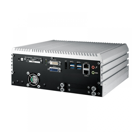
2.2 Front Panel I/O & Functions In Vecow ECS-9200/9100 GTX1050 series family, all I/O connectors are located on the front panel and the rear panel. Most of the general connections to computer device, such as USB, LAN Jack, Audio, Display Port, DVI-I, DVI-D and other additional storage, are placed on the front panel. -
Page 18: Cfast Card
2.2.2 Reset Tact Switch DVI-D SIM 2 SIM 3 LAN 1 SIM 1 WLAN CFast DVI-I LAN 2 It is a hardware reset switch. Use this switch to reset the system without power off the system. Press the Reset Switch for a few seconds, and then reset will be enabled. - Page 19 DVI signal. The DVI output mode supports up to 1920 x 1200 resolution and the DVI is automatically selected according to the display device connected. You will need a DVI-D cable when connecting to a display device. ©Vecow ECS-9200/9100 GTX1050 User Manual GETTING TO KNOW YOUR ECS-9200/9100 GTX1050...
- Page 20 2.2.6 DVI-I Connector DVI-D SIM 2 SIM 3 LAN 1 SIM 1 WLAN CFast DVI-I LAN 2 The DVI-I connector on the front panel supports both DVI and VGA display modes. This connector can output DVI signals. The DVI output mode supports up to 1920x1200 resolution.
-
Page 21: Ethernet Port
Ethernet connection; for example, a hub or a switch. Moreover, both of LAN 1 and LAN 2 support Wake on LAN and Pre-boot functions. The pin-outs of LAN 1 and LAN 2 are listed as follows: ©Vecow ECS-9200/9100 GTX1050 User Manual GETTING TO KNOW YOUR ECS-9200/9100 GTX1050... -
Page 22: Audio Jack
Pin No. 10/ 100Mbps 1000Mbps Pin No. 10/ 100Mbps 1000Mbps E_TX+ MDI0_P ----- MDI2_N E_TX- MDI0_N E_RX- MDI1_N E_RX+ MDI1_P ----- MDI3_P ---- MDI2_P ------ MDI3_N Each LAN port is supported by standard RJ-45 connector with LED indicators to present Active/ Link/ Speed status of the connection. The LED indicator on the right bottom corner lightens in solid green when the cable is properly connected to a 100 Mbps Ethernet network, and it lightens in solid orange when the cable is properly connected to a 1000Mbps Ethernet... - Page 23 Mini PCIe 1 SIM 1 (CN12) Mini PCIe 2 SIM 2 (CN13) Mini PCIe 3 SIM 3 (CN11) Mini PCIe 3 Mini PCIe 2 Mini PCIe 1 CN11 CN12 CN13 ©Vecow ECS-9200/9100 GTX1050 User Manual GETTING TO KNOW YOUR ECS-9200/9100 GTX1050...
-
Page 24: System Fan
SIM 1 WLAN CFast DVI-I LAN 2 There is a system FAN on front side for airflow direction outward. You can adjust the FAN Speed from Vecow BIOS Setting. (refer to 4.3.6_Hardware Monitor_FAN PWM Value) GETTING TO KNOW YOUR ECS-9200/9100 GTX1050... -
Page 25: Rear Panel I/O & Functions
(instant off or delay 4 second) and suspend mode. Pin No. Definition Pin No. Definition Ignition External Power Button V+ External Power Button V- ©Vecow ECS-9200/9100 GTX1050 User Manual GETTING TO KNOW YOUR ECS-9200/9100 GTX1050... -
Page 26: Com Ports
2.3.3 COM Ports DIO 2 DIO 1 DC-IN Isolated Isolated LAN6 LAN5 LAN4 LAN3 COM 1 PIN 1 ~ 8 PIN 11 ~ 18 PIN 1 ~ 8 PIN 11 ~ 18 On | Off COM 2 COM 4 COM 3 HDMI Serial port 1 to 4 (COM 1 to 4) can be configured for RS-232, RS-422, or RS- 485 with auto flow control communication. - Page 27 COM Port MB Connector COM 3 COM 4 CN10 COM 3 & COM 4 MB connector pin out: Pin No. Signal Name Chassis GND CN9 (COM3) CN10 (COM4) CN10 ©Vecow ECS-9200/9100 GTX1050 User Manual GETTING TO KNOW YOUR ECS-9200/9100 GTX1050...
- Page 28 2.3.4 Rear USB 3.0 DIO 2 DIO 1 DC-IN Isolated Isolated LAN6 LAN5 LAN4 LAN3 COM 1 PIN 1 ~ 8 PIN 11 ~ 18 PIN 1 ~ 8 PIN 11 ~ 18 On | Off COM 2 COM 4 COM 3 HDMI There are 4 USB 3.0 connections available supporting up to 5GB per second...
- Page 29 LAN4 Green Off: Non PD Green Light: PD installed & powered green LAN5 Green Off: Non PD Green Light: PD installed & powered green LAN6 Green Off: Non PD ©Vecow ECS-9200/9100 GTX1050 User Manual GETTING TO KNOW YOUR ECS-9200/9100 GTX1050...
- Page 30 2.3.6 Isolated DIO DIO 2 DIO 1 DC-IN Isolated Isolated LAN6 LAN5 LAN4 LAN3 COM 1 PIN 1 ~ 8 PIN 11 ~ 18 PIN 1 ~ 8 PIN 11 ~ 18 On | Off COM 2 COM 4 COM 3 HDMI There is a 32-bit (16-bit DI, 16-bit DO) with 2 DIO connectors in the rear side.
- Page 31 DI reference circuit: Sink Mode (NPN) Power DIO Connector Supply DI_COM (Pin 9) 6-48V DC DI (Pin1-8) Source Mode (PNP) Power DIO Connector Supply DI_COM (Pin 9) 6-48V DC DI (Pin1-8) ©Vecow ECS-9200/9100 GTX1050 User Manual GETTING TO KNOW YOUR ECS-9200/9100 GTX1050...
- Page 32 DO reference circuit: Sink Mode Device DIO Connector (NPN, Default) 6-48V DC DIO_VDC (Pin 20) DO (Pin11-18) DIO_GND (Pin10,19) Source Mode Device DIO Connector (PNP) 6-48V DC DIO_VDC (Pin 20) DO (Pin11-18) DIO_GND (Pin10,19) 2.3.7 3 of 3 Independent Displays DIO 2 DIO 1 DC-IN...
-
Page 33: Main Board Expansion Connectors
2.4.1 Inside View of ECS-9200/9100 GTX1050 Main Board With Connector Location CN10 CN15 CN25 FAN2 JP10 CN18 SATA2 SATA1 FAN1 SODIMM 2 SODIMM 1 Mini PCIe 2 Mini PCIe 3 M2_CN2 Mini PCIe 1 BIOS Battery M2_CN1 ©Vecow ECS-9200/9100 GTX1050 User Manual GETTING TO KNOW YOUR ECS-9200/9100 GTX1050... - Page 34 2.4.2 UPS Power Connector For UPS module optional, we use 4.2mm 2x2p power connector. This system has a UPS power input connector for Optional part UPS Module. CN25 Pin No. Definition Pin No. Definition Ground Ground +VDC_IN +VDC_IN (6~36V, Max.8A) (6~36V, Max.8A) 2.4.3 Miscellaneous Pin Header 2.0mm 2x4p header...
- Page 35 There are 2 DDR4 channel onboard supporting DDR4 2133/1866 and up to 32GB. (Each channel 16GB) SODIMM 2 SODIMM 1 Slot Description Slot Description SODIMM_1 DDR4 Channel A SODIMM_2 DDR4 Channel B ©Vecow ECS-9200/9100 GTX1050 User Manual GETTING TO KNOW YOUR ECS-9200/9100 GTX1050...
- Page 36 2.4.5 BIOS Socket If the BIOS needs to be changed, please contact the Vecow RMA service team. BIOS 2.4.6 SATA Connector Standard 7 PIN SATA Connector There are 2 onboard high performance Serial ATA III. It supports higher storage capacity with less cabling effort and smaller required space.
- Page 37 480 Mbps transfer rate complied with high speed USB specification Rev. 2.0. The USB interface is accessed through one standard USB 2.0 connector. This USB 2.0 does not support wake up function. CN18 ©Vecow ECS-9200/9100 GTX1050 User Manual GETTING TO KNOW YOUR ECS-9200/9100 GTX1050...
- Page 38 Pin No. Definition Pin No. Definition USB +VCC (+V5/Max. 0.5A) DATA- DATA+ Ground 2.4.9 M2DOM Innodisk M2DOM S20/S30 3ME3 is a M.2 based disk module with vertical type form factor. Its mechanical design can help board maker to release up to 90% space of motherboard as well as improve system reliability by its fixed mechanism.
- Page 39 Pin No. Function Pin No. Function +3.3V +3.3V PEDET (NC-PCIe/GND- +3.3V SATA) Mechanical Key REFCLKp REFCLKn WAKE# CLKREQ# PETp0 /SATA-A+ PERST# PETn0 /SATA-A- PERp0 /SATA-B- PERn0 /SATA-B+ PETp1 DEVSLP PETn1 ©Vecow ECS-9200/9100 GTX1050 User Manual GETTING TO KNOW YOUR ECS-9200/9100 GTX1050...
- Page 40 PERp1 PERn1 PETp2 PETn2 PERp2 PERn2 +3.3V +3.3V PETp3 +3.3V PETn3 +3.3V DAS/DSS# (I/O)/LED1# (I)(0/3.3V) PERp3 PERn3 +3.3V +3.3V 2.4.11 Mini PCIe Standard full length Mini PCIe slot: Mini PCIe 2 Mini PCIe 3 Mini PCIe 1 GETTING TO KNOW YOUR ECS-9200/9100 GTX1050...
- Page 41 USB_D+ USB_D- PETp0 PETn0 SMB_DATA SMB_CLK +1.5V PERn0 PERp0 +3.3Vaux PERST# Reserved reserved Reserved Mechanical Key UIM_VPP REFCLK+ UIM_RESET REFCLK- UIM_CLK UIM_DATA CLKREQ# UIM_PWR Reserved 1.5V Reserved WAKE# 3.3Vaux ©Vecow ECS-9200/9100 GTX1050 User Manual GETTING TO KNOW YOUR ECS-9200/9100 GTX1050...
- Page 42 The system’s real-time clock is powered by a lithium battery. It is equipped with Panasonic BR2032 190mAh lithium battery. It is recommended that you do not have to get the lithium battery on your own. If the battery needs to be changed, please contact the Vecow RMA service team. Battery 2.4.13 FAN Header Fan power connector supports for additional thermal requirements.
- Page 43 ECS-9200 GTX1050 provides a LAN header for IEEE 1588. LAN No. Function Function Rear POE LAN3 Intel I210 Rear POE LAN4 Intel I210 Rear POE LAN5 Intel I210 Rear POE LAN6 Intel I210 ©Vecow ECS-9200/9100 GTX1050 User Manual GETTING TO KNOW YOUR ECS-9200/9100 GTX1050...
- Page 44 Pin out: Pin No. Function Pin No. Function SPD0 SPD1 SPD2 SPD3 Ground Ground 2.4.16 COM Port Header ECS-9200/9100 GTX1050 provides 4 COM port headers for internal COM port cable. CN10 Pin out: CN9: CN10: Pin No. Description Port Pin No. Description Port Ground_Frame...
-
Page 45: Main Board Jumper & Deep Switch Settings
To “open” a jumper, you remove the clip. Sometimes a jumper will have three pins, labeled 1, 2 and 3. In this case you would connect either pins 1 and 2, or 2 and 3. ©Vecow ECS-9200/9100 GTX1050 User Manual GETTING TO KNOW YOUR ECS-9200/9100 GTX1050... - Page 46 You may configure your card to match the needs of your application by DIP switch. As below show the DIP switch on and off. 1 : OFF 1 : ON 1 : ON 2 : OFF 2 : OFF 2 : ON 2.5.2 USB Power Jumper Jumper Setting...
- Page 47 RI (Default) Pin Header Pin No. Description +5V (1A max.) COM3 +12V (0.5A max.) RI (Default) Pin Header Pin No. Description +5V (1A max.) COM4 +12V (0.5A max.) RI (Default) ©Vecow ECS-9200/9100 GTX1050 User Manual GETTING TO KNOW YOUR ECS-9200/9100 GTX1050...
- Page 48 2.5.4 PoE Power ON Select JP10 Jumper Setting Function JP10 POE power on at standby power ready JP10 POE power on after system power on (Default) 2.5.5 Clear CMOS/ME Switch Jumper Setting Function *Normal(Default) Clear CMOS Jumper Setting Function *Normal(Default) Clear ME GETTING TO KNOW YOUR ECS-9200/9100 GTX1050...
-
Page 49: Ignition Control
2.6.1 Adjust Ignition Control Modes ECS-9200/9100 GTX1050 series provides 16 modes of different power on/off delay periods adjustable via SW2 switch. The default rotary switch is set to 0 in ATX/AT power mode. ©Vecow ECS-9200/9100 GTX1050 User Manual GETTING TO KNOW YOUR ECS-9200/9100 GTX1050... - Page 50 The modes are listed in the following table: Item Power on delay Power off delay Switch Position ATX mode No delay No delay No delay 5 seconds No delay 10 seconds No delay 20 seconds 5 seconds 30 seconds 5 seconds 60 seconds 5 seconds 90 seconds...
- Page 51 3. For proper ignition control, the power button setting should be “Power down” mode. In Windows, for example, you need to set “When I press the power button” to "Shut down." ©Vecow ECS-9200/9100 GTX1050 User Manual GETTING TO KNOW YOUR ECS-9200/9100 GTX1050...
- Page 52 2.6.3 Smart Battery Protection The system with “Ignition Control” can perform Smart Battery Protection, namely Low Battery Detection. When the system is running on a battery and its voltage drops below the threshold, the system will automatically shut down. The Low Battery Detection is implemented in the ignition control MCU FW and as a default function.
-
Page 53: Chapter 3 System Setup
SYSTEM SETUP 3.1 How to Open Your ECS-9200/9100 GTX1050 Step 1 Remove hole plugs. Step 2 Remove two F#6-32 screws (circled in red) and two F-M3 screws (circled in yellow) on the bottom side. ©Vecow ECS-9200/9100 GTX1050 User Manual HARDWARE INSTALLATION... - Page 54 Step 3 Finish Step1 and 2. Step 4 Remove one KHS#6-32x6 screw. Step 5 Open the module. HARDWARE INSTALLATION...
- Page 55 Step 6 Finish. Step 7 Remove two F-#6-32 screws at the bottom side. Step 8 Remove the cover. Remove one screw KHS-#6-32 and SSD/ HDD tray at front panel. ©Vecow ECS-9200/9100 GTX1050 User Manual HARDWARE INSTALLATION...
- Page 56 Step 9 Remove SSD/HDD module. Step 10 Be careful pulling out SATA(yellow), power SATA(blue) and COM cables(red). Step 11 Remove four KHS-#6-32 screws at the rear panel. HARDWARE INSTALLATION...
-
Page 57: Installing Cpu
Step 12 Finish. 3.2 Installing CPU Step 1 Remove one F #6-32 and pick up chock bracket. Step 2 Remove eight PH-M3 and four M3x11 spring screws and pick up mother board. ©Vecow ECS-9200/9100 GTX1050 User Manual HARDWARE INSTALLATION... - Page 58 Step 3 CPU socket. Step 4 Open the CPU socket. (Be careful CPU pins) HARDWARE INSTALLATION...
- Page 59 Step 5 Install CPU on the socket. Step 6 Finish. Step 7 Close CPU socket and finish. ©Vecow ECS-9200/9100 GTX1050 User Manual HARDWARE INSTALLATION...
-
Page 60: Installing Ddr4 So-Dimm Modules
3.3 Installing DDR4 SO-DIMM Modules Step 1 DDR4 RAM module into SO-DIMM slot. Step 2 Make sure the RAM module is locked by the memory slot. HARDWARE INSTALLATION... -
Page 61: Installing Mini Pcie Card
3.4 Installing Mini PCIe Card Step 1 Install Mini PCIe card into the Mini PCIe socket. Step 2 Fasten one M2.5 screw. ©Vecow ECS-9200/9100 GTX1050 User Manual HARDWARE INSTALLATION... -
Page 62: Installing Cfast Card
3.5 Installing CFast Card Step 1 Remove 2 pcs F-M3x4 screws on CFast & SIM cover. Step 2 Before inserting CFast & SIM Cards, make sure the system power is not plugged. Step 3 Insert CFast card and push to lock. Step 4 Finish. -
Page 63: Installing Sim Card
Step 1 Remove 2 pcs F-M3x4 screws on CFast & SIM cover. Step 2 Before inserting CFast & SIM Cards, make sure the system power is not plugged. Step 3 Insert SIM card and push to lock. Step 4 Finish. ©Vecow ECS-9200/9100 GTX1050 User Manual HARDWARE INSTALLATION... -
Page 64: Installing Ssd/Hdd
3.7 Installing SSD/HDD Step 1 Trigger and open SSD/HDD tray. Step 2 Insert 2.5” SSD/HDD in the tray and fasten two F-M3x4 screws. HARDWARE INSTALLATION... - Page 65 Step 3 Finish. Step 4 Install SSD/HDD. ©Vecow ECS-9200/9100 GTX1050 User Manual HARDWARE INSTALLATION...
-
Page 66: Installing
3.8 Installing M.2 Step 1 M.2 slot. Step 2 Fasten one M3 screw. HARDWARE INSTALLATION... -
Page 67: Installing M2Dom
3.9 Installing M2DOM Step 1 M2DOM slot. Step 2 M2DOM module. ©Vecow ECS-9200/9100 GTX1050 User Manual HARDWARE INSTALLATION... - Page 68 Step 3 Install M2DOM module with slot. Step 4 Lock two M2 screws with slot. HARDWARE INSTALLATION...
-
Page 69: Mounting Your Ecs-9200/9100 Gtx1050
Step 1 Ensure the screw holes on the right and left sides of the upper case match the ones on ECS-9200/9100 GTX1050 wall mount bracket. Step 2 Fasten 4pcs KHS#6-32 screws and then finish. ©Vecow ECS-9200/9100 GTX1050 User Manual HARDWARE INSTALLATION... - Page 70 3.10.2 VESA Mount Step 1 ECS-9200/9100 GTX1050 and VESA Mount. Step 2 Take ECS-9200/9100 GTX1050 and VESA Mount with fasten 4pcs KHS#6-32 screws. HARDWARE INSTALLATION...
- Page 71 Step 3 Fasten four KHS#6-32 screws and then finish. Step 4 Finish. Step 5 There are two sizes of VESA, 75x75mm(red) and 100x100mm(yellow). ©Vecow ECS-9200/9100 GTX1050 User Manual HARDWARE INSTALLATION...
- Page 72 3.10.3 Din Rail Kit Step 1 ECS-9200/9100 GTX1050 and Din Rail Kit. Step 2 Take ECS-9200/9100 GTX1050 and Din Rail Kit and fasten four KHS#6-32 screws in the four marked corners. HARDWARE INSTALLATION...
- Page 73 Step 3 Fasten four KHS#6-32 screws and then finish. Step 4 Finish. Step 5 ECS-9200/9100 GTX1050 With Din Rail. ©Vecow ECS-9200/9100 GTX1050 User Manual HARDWARE INSTALLATION...
-
Page 74: Chapter 4 Bios Setup
BIOS SETUP 4.1 Entering BIOS SETUP Figure 4-1: Entering Setup Screen BIOS provides an interface for users to check and change system configuration. The BIOS setup program is accessed by pressing the <Del> key when POST display output is shown. BIOS AND DRIVER SETTING... -
Page 75: Main
Set the time. Use <Tab> to switch between time elements. 4.3 Advanced Figure 4 3: BIOS Advanced Menu Select advanced tab to enter advanced BIOS setup options such as CPU configuration, SATA configuration, and USB configuration. ©Vecow ECS-9200/9100 GTX1050 User Manual BIOS AND DRIVER SETTING... -
Page 76: Acpi Settings
4.3.1 ACPI Settings Figure 4 3-1: ACPI Settings Enable Hibernation Enables or disables system's ability to hibernate (OS/S4 sleep state). This option may not be effective with some OS. ACPI Sleep State Selects the highest ACPI sleep state the system will enter when the SUSPEND button is pressed. - Page 77 4.3.5 IT8786 Super IO Configuration Figure 4-3-5: Super IO Settings Serial Port 1 Configuration Set parameters of serial port 1 (COM 1). Serial Port 2 Configuration Set parameters of serial port 2 (COM 2). ©Vecow ECS-9200/9100 GTX1050 User Manual BIOS AND DRIVER SETTING...
-
Page 78: Hardware Monitor
Serial Port 3 Configuration Set parameters of serial port 3 (COM 3). Serial Port 4 Configuration Set parameters of serial port 4 (COM 4). 4.3.6 Hardware Monitor Figure 4 3-6: Hardware Monitor Settings The IT8786 SIO features an enhanced hardware monitor providing thermal, fan speed, and system voltages' status monitoring. - Page 79 Enable/disable CPU Advanced Encryption Standard instructions. Boot performance mode Select the performance state that the BIOS will set before OS handoff. Intel(R) SpeedStep(tm) Allows more than two frequency ranges to be supported. Turbo Mode Turbo Mode. ©Vecow ECS-9200/9100 GTX1050 User Manual BIOS AND DRIVER SETTING...
-
Page 80: Sata Configuration
CPU C state Enable or disable CPU C states. Enhanced C-states Enable/disable C1E. When enabled, CPU will switch to minimum speed when all cores enter C-State. Package C State limit Package C State limit. Intel TXT(LT) Support Enables or disables Intel (R) TXT (LT) support. 4.3.9 Intel TXT Information Figure 4 3-9: Intel TXT Information Display Intel TXT information. - Page 81 Identifies that the SATA port is connected to solid state drive or hard disk drive. 4.3.11 Acoustic Management Configuration Figure 4 3-11: Acoustic Management Settings Acoustic Management Configuration Option to enable or disable automatic acoustic management. ©Vecow ECS-9200/9100 GTX1050 User Manual BIOS AND DRIVER SETTING...
- Page 82 4.3.12 CSM Configuration Figure 4 3-12: CSM Settings CSM Support Enable/disable CSM support GateA20 Active UPON REQUEST - GA20 can be disabled using BIOS services. ALWAYS - do not allow GA20 to be disabled; this option is useful when any RT code is executed above 1MB.
- Page 83 Maximum time the device will take before it properly reports itself to the Host Controller. 'Auto' uses default value, for a root port it is 100 ms, for a hub port the delay is taken from the hub descriptor. ©Vecow ECS-9200/9100 GTX1050 User Manual BIOS AND DRIVER SETTING...
-
Page 84: Chipset
4.4 Chipset Figure 4-4: BIOS Chipset Menu System Agent (SA) Configuration System Agent (SA) parameters. PCH-IO Configuration PCH parameters. GPIOManager Configuration GPIOManager parameters. 4.4.1 System Agent (SA) Configuration Figure 4-4-1: System Agent Settings VT-d VT-d capability. GMM Device (B0:D8:F0) Enable/disable SA GMM device. Above 4GB MMIO BIOS assignment Enable/disable above 4GB MemoryMappedIO BIOS assignment. - Page 85 Select DVMT5.0 Total Graphic Memory size used by the Internal Graphics Device. Cd Clock Frequency Select the highest Cd Clock frequency supported by the platform. 4.4.3 PEG Port Configuration (SA) Figure 4-4-3: PEG Port Configuration PEG port options for PCIe device. ©Vecow ECS-9200/9100 GTX1050 User Manual BIOS AND DRIVER SETTING...
- Page 86 4.4.4 Memory Information of System Agent (SA) Figure 4-4-4: Memory Information Displays memory information. 4.4.5 PCH-IO Configuration Figure 4-4-5: PCH-IO Settings PCH LAN Controller Enable or disable onboard NIC. Wake on LAN Enable or disable integrated LAN to wake the system. (The wake On LAN cannot be disabled if ME is on at Sx state.) Serial IRQ Mode Configure serial IRQ mode.
- Page 87 PCI Express Native Support Enable/Disable. This feature is available in vista and beyond Windows OS. 4.4.7 BIOS Security Configuration of PCH-IO Figure 4-4-7: BIOS Security Settings BIOS Lock Enable/disable the PCH BIOS Lock Enable (BLE bit) feature. ©Vecow ECS-9200/9100 GTX1050 User Manual BIOS AND DRIVER SETTING...
- Page 88 4.4.8 SB Porting Configuration of PCH-IO Figure 4-4-8: RAID ROM Settings SATA RAID ROM Legacy ROM: Legacy option ROM UEFI Driver: UEFI Raid Driver Both: Run the Legacy Option ROM and UEFI driver. 4.4.9 GPIO Manager Configuration Figure 4-4-9: GPIO Manager Settings VGA Enable Enable: VGA display output enabled Disable: VGA display output disabled...
-
Page 89: Security
Discard or save changes option in setup does not have any impact on HDD when password is set or removed. If the 'Set HDD User Password' option is gray, do power cycle to enable the option again. ©Vecow ECS-9200/9100 GTX1050 User Manual BIOS AND DRIVER SETTING... -
Page 90: Boot
4.6 Boot Figure 4-6: BIOS Boot Menu Setup Prompt Timeout Number of seconds to wait for setup activation key. 65535(0xFFFF) means indefinite waiting. Bootup NumLock State Select the keyboard NumLock state. Quiet Boot Enables or disables Quiet Boot option. Boot Option Sets the system boot order. -
Page 91: Save & Exit
Restore/load default values for all the setup options. Save as User Defaults Save the changes done so far as user defaults. Restore User Defaults Restore the user defaults to all the setup options. ©Vecow ECS-9200/9100 GTX1050 User Manual BIOS AND DRIVER SETTING... -
Page 92: Appendix A : Isolated Dio Guide
APPENDIX A : Isolated DIO Guide A.1 Function Description ECS-9200 GTX1050 offers two 16-bit DIO (Isolated / Non-Isolated) 20-pin terminal block connector, a watchdog timer, and a 4-port POE. Isolated DIO pins are fix by Hardware design that cannot change in / out direction in runtime process. - Page 93 DO reference circuit: Sink Mode Device DIO Connector (NPN, Default) 6-48V DC DIO_VDC (Pin 20) DO (Pin11-18) DIO_GND (Pin10,19) Source Mode Device DIO Connector (PNP) 6-48V DC DIO_VDC (Pin 20) DO (Pin11-18) DIO_GND (Pin10,19) Appendix A ©Vecow ECS-9200/9100 GTX1050 User Manual...
- Page 94 A.3 Software Package Contain Distribution folder include x32 and x64 versions, use batch file for installation. There are included as fallowed: Win7_32.bat: Installation for 32-bit driver Win7_64.bat: Windows update package which driver required (need to restart), and Installation for 64-bit driver Win8_32.bat, Win8_64.bat: Installation for driver, and guideline to Framework 3.5 distribution for sample...
- Page 95 A.4 Sample Sample folder includes x32 and x64 versions, shown as below: Sample ECS9K2.exe, shown as below: Appendix B ©Vecow ECS-9200/9100 GTX1050 User Manual...
- Page 96 DIO1 / DIO2 group: Isolate check button: DIO type of DIO configuration, isolated / non-isolated, defined in ECS-9000 series user manual. Read button: Set DIO configuration to get DI / DIO input state. DO type check button: User setting, DO type of DIO configuration to setup 8 pins - Source / Sink. Use for Write (DO) button activate.
- Page 97 User setting, POE port writable of POE configuration. Use for Write button activate. POE port mode texts (port 4 ~ port 1): User setting, POE port mode of POE configuration. Use for Write button activate. Appendix B ©Vecow ECS-9200/9100 GTX1050 User Manual...
-
Page 98: Appendix B : Software Functions
APPENDIX B : Software Functions B.1 Driver API Guide In Runtime folder, on ECS9K2.h: _DLL_IMPORT_ definition is used on LoadLibrary API for ECS9K2.dll. ECS9K_EXPORTS definition is used on ECS9K2.dll building. Otherwise, that is used to compile with ECS9K2.lib. BOOL Initial(BYTE Isolate_Type, BYTE DIO_NPN) Initial machine for DIO, watchdog timer, and POE Isolate_Type: DIO type 1: Isolated DIO;... - Page 99 BOOL SetDO2(BYTE DO) Set isolated DIO output (DO) DO ([7:0]): Output state, pin setting by hexadecimal bitmask 1: High; 0: Low Return: TRUE (1): Success; FALSE (0): Fail (Initial error, or hardware problem) Appendix B ©Vecow ECS-9200/9100 GTX1050 User Manual...
- Page 100 BOOL GetDIO1(WORD *DI) BOOL GetDIO2(WORD *DI) Get non-isolated DIO input (DIO input) DI ([15:0]): Input state, pin setting by hexadecimal bitmask 1: High; 0: Low Return: TRUE (1): Success; FALSE (0): Fail (Initial error, or call by pointer error, or hardware problem) BOOL SetDIO1(WORD DO) BOOL SetDIO2(WORD DO)
- Page 101 Set POE output POE ([3:0]): POE state, pin setting by hexadecimal bitmask 1: On; 0: Off Return: TRUE (1): Success; FALSE (0): Fail (Initial error, or out of range error, or hardware problem) Appendix C ©Vecow ECS-9200/9100 GTX1050 User Manual...
-
Page 102: Appendix C : Raid Installation Guide
APPENDIX C : RAID Installation Guide C.1 SATA Mode for RAID Please select SATA device to RAID mode on BIOS menu. Advanced → SATA Configuration → SATA Mode Selection C.2 OS Installation ECS-9200/9100 GTX1050 is featured with six SATA, include two internal SATA, three mSATA and one CFast. - Page 103 C.6 Create RAID Volume ECS-9200/9100 GTX1050 is featured with four SATA HDDs for RAID volume, so there are three options for choose on this page. Let’s take RAID 1 as example, please select ”RAID 1”. Appendix C ©Vecow ECS-9200/9100 GTX1050 User Manual...
- Page 104 C.7 Disk Management : Partition the Disk After RAID 1 volume created, you can see the figure of SATA device allocation. You will find “Volume_0000” in SATA device at BIOS menu. To start Disk Management tool, select "initialize disk." Then add “Logical Device” for Windows access. C.8 RAID HDD Fail After RAID 1 volume created, you can see the figure of SATA device allocation.
- Page 105 There is a warning will pop-up to ask you if the disk is not a member of original RAID volume. If you press “Rebuild”, it will replace the broken SATA HDD to the last one SATA HDD of RAID volume. Appendix C ©Vecow ECS-9200/9100 GTX1050 User Manual...
-
Page 106: Appendix D : Power Consumption
APPENDIX D : Power Consumption Testing Board ECS-9200 GTX1050 8GB X 2 USB-1 USB Keyboard Logitech K120 USB-2 USB Mouse Microsoft 1113 USB-3 USB Flash Transecnd 3.0 8GB USB-4 USB Flash Transecnd 3.0 8GB CFAST innodisk CFast 3ME3 64GB SATA 0 MEMXPRO M3A 256GB SATA 1 TOSHIBA SSD THNS064GE4BBDC 64GB... - Page 107 3D usage with 3D Power Input Current Consumption Current Consumption Core™ i7- 4.066A 60.99W 7.339A 110.09W 6700 Core™ i7- 2.569A 61.66W 4.648A 111.55W 6700 Core™ i7- 1.768A 63.65W 3.158A 113.69W 6700 Appendix D ©Vecow ECS-9200/9100 GTX1050 User Manual...
-
Page 108: Appendix E : Supported Memory & Storage List
APPENDIX E : Supported Memory & Storage List E.1 Supported Memory List Testing Board ECS-9200 GTX1050 Memory Test version: 5.1 BurnInTest V8.1 E.2 Test Item Remove Channel Memory Test Burn In Flash BIOS Battery PASS PASS PASS PASS *1(Socket 1) PASS PASS PASS... - Page 109 Wild Temp. Apacer 16GB DDR4-2400 75.DA4GJ.G010B 201646411074 25ºC Wild Temp. E.4 ECC Test Temp. Brand Info NOTE & S\N (Celsius) C96644-0001 85ºC Transcend 8GB 8G 2Rx8 DDR4 ECC Wild Temp. 2133 ECCSO C96644-0002 85ºC Appendix E ©Vecow ECS-9200/9100 GTX1050 User Manual...
- Page 110 E.5 Supported Storage Device List Type Brand Model Capacity Intel Intel-310 SSDMAEMC080G2 80GB mSATA Silicon SP128GIMSA301SW0 128GB Power Transcend SSD370 TS64GSSD370 64GB SSD M3A MI3MA1212802WN 128GB Memxpro SSD M3A MI3MA1225604WN 256GB SATA SSD SSD M3A MI3MA1251208WN 512GB Innodisk 3MR3-P DRS25-64GD70BCAQC 64GB Silicon SP128GISSD301RW0...
-
Page 111: Appendix F : Graphics Performance
PASS PASS PASS PASS PASS PASS Testing Equipment ® CPU : Intel Core™ i7-6700 IMB : ECS-9200 Memory : MEMXPRO 8GB*2 ** If more help is needed, please contact Vecow technical support ** Appendix F ©Vecow ECS-9200/9100 GTX1050 User Manual... - Page 112 No part of this publication may be reproduced in any form or by any means, electric, photocopying, or recording, without prior authorization from the publisher. The rights of all the brand names, product names, and trademarks belong to their respective owners. © Vecow Co., Ltd. 2017. All rights reserved.
Need help?
Do you have a question about the ECS-9240-GTX1050T and is the answer not in the manual?
Questions and answers