Table of Contents
Advertisement
Quick Links
Advertisement
Table of Contents

Related Manuals for AXIOMTEK SCM186


Summary of Contents for AXIOMTEK SCM186
- Page 1 SCM186 NXP i.MX 8M Plus ARM-based SMARC Module Hardware & BSP User’s Manual...
-
Page 2: Disclaimers
Axiomtek does not make any commitment to update the information in this manual. Axiomtek reserves the right to change or revise this document and/or product at any time without notice. No part of this document may be reproduced, stored in a retrieval system, or transmitted, in any form or by any means, electronic, mechanical, photocopying, recording, or otherwise, without the prior written permission of Axiomtek Co., Ltd. -
Page 3: Esd Precautions
Wear a wrist-grounding strap, available from most electronic component stores, when handling boards and components. Trademarks Acknowledgments Axiomtek is a trademark of Axiomtek Co., Ltd. ARM is a trademark of ARM Ltd. Other brand names and trademarks are the properties and registered brands of... -
Page 4: Table Of Contents
Table of Contents Disclaimers ....................ii ESD Precautions ..................iii Section 1 Introduction..........1 Features ..................... 2 Specifications ..................2 Block Diagram ................... 4 Section 2 Board and Pin Assignments ..... 5 Board Dimensions and Fixing Holes ..........5 Board Layout ..................6 Installing Heatsink ................ - Page 5 This page is intentionally left blank.
-
Page 7: Section 1 Introduction
Section 1 Introduction The SCM186 is a SMARC 2.0 module based on NXP i.MX 8M Plus SoC Quad A53 with LPDDR4 4GB RAM and 8GB eMMC. The I/O includes HDMI, LVDS, LAN and USB. It integrates system memory, storage as embedded eMMC or SD card slot, UART, audio, USB, dual-channel LVDS, MIPI-CSI, CANbus, GPIO, PCIe and various features. -
Page 8: Features
SCM186 NXP i.MX 8M Plus ARM-based Evaluation Kit 1.1 Features ⚫ SMARC 2.0 (82 x 50 mm) Core Processor ⚫ NXP i.MX 8M Plus 1.8GHz SoC with Quad A53 ⚫ Neural Processing Unit (NPU), up to 2.3 TOPS ⚫ Cortex-M7 for Real-time Control ⚫... - Page 9 SCM186 NXP i.MX 8M Plus ARM-based Evaluation Kit ⚫ ◼ Dual UART with TX/RX/RTS/CTS ◼ Single UART TX/RX (for debug console) ⚫ ◼ Triple I2C interface ⚫ QSPI ◼ Single QSPI ⚫ ◼ Single SPI ⚫ CANbus ◼ Dual CANbus ⚫...
-
Page 10: Block Diagram
SCM186 NXP i.MX 8M Plus ARM-based Evaluation Kit 1.3 Block Diagram Introduction... -
Page 11: Section 2 Board And Pin Assignments
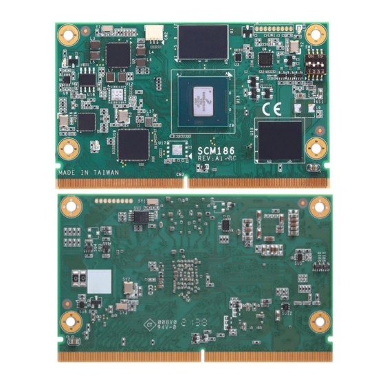
SCM186 NXP i.MX 8M Plus ARM-based Evaluation Kit Section 2 Board and Pin Assignments 2.1 Board Dimensions and Fixing Holes Top View Unit: mm Bottom View Board and Pin Assignments... -
Page 12: Board Layout
SCM186 NXP i.MX 8M Plus ARM-based Evaluation Kit 2.2 Board Layout Top View Bottom View Board and Pin Assignments... -
Page 13: Installing Heatsink
Below procedures illustrate how to install the heatsink on SCM186. 2.3.1 Heatsink The heatsink is designed for the SCM186 module. The thermal pad on the heatsink is designed to make contact with the necessary components on the SCM186 module. When mounting the... -
Page 14: Heat Spreader
SCM186 module, and then a customized heatsink or thermal chassis must be completely contacted with the heat spreader. This is especially critical for SCM186 module that is with high CPU speed to ensure that the heat spreader acts as a proper thermal interface for cooling solutions. -
Page 15: Switch Settings
SCM186 NXP i.MX 8M Plus ARM-based Evaluation Kit 2.4 Switch Settings 2.4.1 SWITCH (SW1) SCM186 switch settings mode as followed. Function Setting Switch Setting Boot by Carrier Board’s setting SW1 OFF (SCM186 Default) SW2 OFF SW3 OFF SW4 OFF OS Flash... -
Page 16: Smarc Module Top/Bottom Side Pinout Table
SCM186 NXP i.MX 8M Plus ARM-based Evaluation Kit 2.6 SMARC Module Top/Bottom Side Pinout Table P-Pin Primary (Top) Side S-Pin Secondary (Bottom) Side SMB_ALERT# I2C2_SCL I2C2_SDA CSI1_CK+ CSI1_CK- I2C3_SCL CSI1_DP0 I2C3_SDA CSI1_DN0 CSI0_CK+ CSI0_CK- CSI1_DP1 CSI1_DN1 CSI0_DP0 CSI0_DN0 CSI1_DP2 CSI1_DN2... - Page 17 SCM186 NXP i.MX 8M Plus ARM-based Evaluation Kit P-Pin Primary (Top) Side S-Pin Secondary (Bottom) Side SDIO_D2 AUDIO _RXD SDIO_D3 AUDIO _TXC SPI0_CS0# SPI0_CK SPI0_MISO I.MX8M Plus SoC_AE28 pin (Default 0V) SPI0_MOSI I2C_GP_CK I2C_GP_DAT I2S2_LRCK I2S2_SDOUT I2S2_SDIN I2S2_CK QSPI_CS0# QSPI_CKO...
- Page 18 SCM186 NXP i.MX 8M Plus ARM-based Evaluation Kit P-Pin Primary (Top) Side S-Pin Secondary (Bottom) Side PCIE_A_TX- HDMI_D2+ HDMI_D2- HDMI_D1+ HDMI_D1- HDMI_D0+ HDMI_D0- P100 S100 P101 HDMI_CK+ S101 P102 HDMI_CK- S102 P103 S103 P104 HDMI_HPD S104 P105 HDMI_DDC_CK S105 P106...
- Page 19 SCM186 NXP i.MX 8M Plus ARM-based Evaluation Kit P-Pin Primary (Top) Side S-Pin Secondary (Bottom) Side P137 SER2_RX S137 LVDS0_3+ P138 SER2_RTS#_INPUT S138 LVDS0_3- P139 SER2_CTS#_OUTPUT S139 I2C2_SCL P140 SER3_TX S140 I2C2_SDA P141 SER3_RX S141 LCD0_BKLT_PWM P142 S142 P143 CAN0_TX...
- Page 20 SCM186 NXP i.MX 8M Plus ARM-based Evaluation Kit This page is intentionally left blank. SCB184 Baseboard Introduction...
-
Page 21: Section 3 Herodotus Bsp User Guide
SCM186 NXP i.MX 8M Plus ARM-based Evaluation Kit Section 3 Herodotus BSP User Guide Abbreviations Digital Visual Interface DisplayPort Factory Test Suite Mechanical System Board Support Package Herodotus BSP User Guide... -
Page 22: System Introduction
SCM186 NXP i.MX 8M Plus ARM-based Evaluation Kit System Introduction The SCM186 with SCB184 is designed as an evaluation kit, the SCM186 stands for a SoM, i.e., the system-on-module by SMARC spec., and the SCB184 stands for the part of carrier. We will note the set of evaluation kit as Herodotus for later sections. -
Page 23: Image Programming
SCM186 NXP i.MX 8M Plus ARM-based Evaluation Kit Image Programming This section explains how to flash BSP image to eMMC/SD card. 3.3.1 Accessories Requirement 3.3.1.1 Flash in SD card To flash the image in SD card for Herodotus platform, following items are required: ⚫... - Page 24 SCM186 NXP i.MX 8M Plus ARM-based Evaluation Kit Example: Assume SD card attached at /dev/sdf, image name is imx-image-full-scm186.wic.bz2 $ bzcat imx-image-full-scm186.wic.bz2 | sudo dd of=/dev/sdf bs=1M conv=fsync 0+1290634 records in 0+1290634 records out 6493345792 bytes (6.5 GB, 6.0 GiB) copied, 153.449 s, 42.3 MB/s 3.3.1.3 Flash Image by Windows PC...
- Page 25 Terminal will show Done after flash successful. <user disk path> ⚫ Remove Micro USB cable and follow ch.3.4 for boot steps. p.s. The image flash package is maintained by Axiomtek, please contact us for more details. Herodotus BSP User Guide...
-
Page 26: Boot The Board
Please check the following items before booting the system, some procedures may require to be operated without the case. Boot from EMMC To make sure the switch on SCM186 SoM is set 0b’1010’ as below figure. ⚫ Set switch as 1010,... -
Page 27: Boot Procedure
SCM186 NXP i.MX 8M Plus ARM-based Evaluation Kit 3.4.2 Boot Procedure Please follow below steps to boot up Herodotus platform. Make sure the boot setting for eMMC or SD, then connect the power cord to DC Input to boot the board. -
Page 28: Linux Peripheral Testing
SCM186 NXP i.MX 8M Plus ARM-based Evaluation Kit Linux Peripheral Testing This section of the document explains about how to test the peripherals in Linux OS level for Herodotus platform. 3.5.1 Test Items This part of the document includes all peripherals on Herodotus platform... - Page 29 SCM186 NXP i.MX 8M Plus ARM-based Evaluation Kit ⚫ Execute below command to check which device node that USB attached. USB will attach at /dev/sd<x>. sh-5.1# fdisk -l ⚫ Create a directory as temp mount node sh-5.1# mkdir <temp_directory_name> ⚫...
- Page 30 SCM186 NXP i.MX 8M Plus ARM-based Evaluation Kit 3.5.1.3 HDMI Herodotus board provides one HDMI port. This port supports up to 1920x1080@60fps. ⚫ To play a video file, please execute the below command. The test takes .mp4 with audio track, please refer to the log for detail.
- Page 31 SCM186 NXP i.MX 8M Plus ARM-based Evaluation Kit 3.5.1.4 Ethernet Network Devices Test Although SCB184 has dual Ethernet ports, Herodotus supports only one Ethernet port (LAN1), this section explains how to check MAC address and test the Ethernet. ⚫ Connect the Ethernet cable and execute the below command to check MAC address is same with the sticker on the RJ45 connector, and then check IP address has been set by DHCP.
- Page 32 SCM186 NXP i.MX 8M Plus ARM-based Evaluation Kit 3.5.1.5 Serial Port Herodotus supports the serial port with different mode & baud rates. This section explains how to test the switch mode and test. Configuration for Serial Ports Herodotus supports below several serial ports, these ports provide varies protocols, please refer to following list for the supported list.
- Page 33 SCM186 NXP i.MX 8M Plus ARM-based Evaluation Kit Serial Port Test The below table and figure present that serial port pin define on Herodotus board ttymxc0 ttymxc2 ⚫ Switch the mode and connect the correct pin with serial port of host PC or loopback by using cable.
- Page 34 SCM186 NXP i.MX 8M Plus ARM-based Evaluation Kit Example: Host PC sent message, Herodotus received Herodotus BSP User Guide...
- Page 35 SCM186 NXP i.MX 8M Plus ARM-based Evaluation Kit Herodotus sends message, Host PC received. Herodotus BSP User Guide...
- Page 36 SCM186 NXP i.MX 8M Plus ARM-based Evaluation Kit 3.5.1.6 I2C Herodotus supports 2*i2c connector for using external i2c devices. This section explains how to control external i2c devices by i2c-tool. I2C4 I2C3 SCB184 I2C Bus Example Connector Control i2cdetect –y 0 I2C3 i2cdetect –y 2...
- Page 37 SCM186 NXP i.MX 8M Plus ARM-based Evaluation Kit i2cset – This function can set value to data address in i2c devices. ⚫ Usage: i2cset [-f] [-y] [-m MASK] [-r] [-a] I2CBUS CHIP-ADDRESS DATA-ADDRESS [VALUE] ... [MODE] I2CBUS is an integer or an I2C bus name...
- Page 38 SCM186 NXP i.MX 8M Plus ARM-based Evaluation Kit 3.5.1.7 GPIO Herodotus supports GPIO connector for 10 external GPIO control. This section explains how to control GPIO. To exercise the external GPIO, it needs to export each GPIO by their GPIO chip number, there are, the following table and command demonstrates the GPIO chip number and several steps to configure GPIO.
- Page 39 SCM186 NXP i.MX 8M Plus ARM-based Evaluation Kit 3.5.1.8 Audio Codec Herodotus supports the SGTL5000 audio devices. This section explains how to test SGTL5000 audio codecs. Please following the pin definition to connect audio signal. ⚫ To list the available audio interfaces, please execute the below command.
- Page 40 SCM186 NXP i.MX 8M Plus ARM-based Evaluation Kit 3.5.1.9 CAN Herodotus supports the 2 CAN connectors. This section explains how to execute and test CAN modules. CAN2 CAN1 Note: can0 is mapping to CAN1, can1 is mapping to CAN2 on board.
- Page 41 SCM186 NXP i.MX 8M Plus ARM-based Evaluation Kit 3.5.1.10 PCIe Herodotus supports PCIe switch and End point devices. This section explains how to list the connected PCIe switches and End point devices. ⚫ Connect the PCIe device in Herodotus platform before powering ON.
- Page 42 SCM186 NXP i.MX 8M Plus ARM-based Evaluation Kit 3.5.1.12 QSPI/ECSPI Herodotus supports 1 QSPI and 1 ECSPI external connector. User can connect spi device and porting customize configuration. QSPI ECSPI Please follow below commands to execute QSPI/ECSPI device (using SPI NOR flash for example) ⚫...
- Page 43 SCM186 NXP i.MX 8M Plus ARM-based Evaluation Kit 3.5.1.13 PWN FAN Herodotus supports pwm fan connector using typical 4 pin fan. This section explains how to control pwm fan. Please follow below commands to execute pwm fan. ⚫ To change directory to pwm chip path, execute the below command.
Need help?
Do you have a question about the SCM186 and is the answer not in the manual?
Questions and answers