Advertisement
Jumper Settings
Before applying power to the SDM500L, please make sure onboard jumper
is in factory default position.
Jumper
Description
JP1
Clear CMOS
JP2
AUTO POWER ON
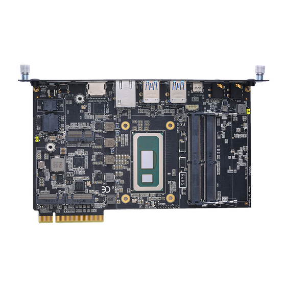
Connectors
Connector
260‐Pin DDR4 Channel A SO‐DIMM Socket
260‐Pin DDR4 Channel B SO‐DIMM Socket
GbE Lan port (RJ45)
M.2 Key B socket
M.2 Key M socket
USB3.1 Gen1 Type‐A Stack Connector
USB3.1 Gen1 Type‐A Stack Connector
Audio Jack (MIC In)
Audio Jack (Line Out)
Reset Button
HDMI Type A (eDP) (optional)
Type C connector (optional)
Battery Header
M.2 Key E socket
Power Button
FAN Header
SDM Edge Connector
Status LED
Note: Please refer to the Axiomtek website
the complete user's manual, drivers and utilities. User's manual and
related documents are in Acrobat PDF format.
4
Setting
1-2 : Normal (Default)
2-3 : Clear CMOS
1-2 : Enable. (AT Mode) (Default).
2-3 : Disable. (ATX Mode)
Description
DIMM1
DIMM2
LAN1
CN2
CN3
CN4
CN5
CN6
CN7
CN8
CN9
CN10
BAT1
NGFF1
SW1
FAN1
J1
D25
https://www.axiomtek.com.tw/
for
942000000100
©
Copyright 2021 Axiomtek Co., Ltd.
Version A1.1 October 2021
Printed in Taiwan
SDM500L Quick Installation Guide
Checklist
SDM500L Board x1
Quick Installation Guide x1
Note: Please contact your local vendors if any damaged or missing items. DO
NOT apply power to the board if there is any damaged component.
Module Dimensions and Fixing Holes
100
59.65
4
0
195
186
942000000100
©
Copyright 2021 Axiomtek Co., Ltd.
Version A1.1 October 2021
Printed in Taiwan
15.5
109.9
89.982
40.123
4
16.34
1.6
1
Advertisement
Table of Contents

Related Manuals for AXIOMTEK SDM500L


Summary of Contents for AXIOMTEK SDM500L
- Page 1 SDM500L Quick Installation Guide Jumper Settings Before applying power to the SDM500L, please make sure onboard jumper is in factory default position. Checklist Jumper Description Setting SDM500L Board x1 Quick Installation Guide x1 1-2 : Normal (Default) Clear CMOS 2-3 : Clear CMOS Note: Please contact your local vendors if any damaged or missing items.
- Page 2 Key E 2230 E: M3*3L Pan Head Screw(Silver) E: M3*3L Pan Head Screw(Silver) F: 5H*4.2L*M3 Hex Copper Stand off(Long) A: SDM500L IO Bracket, 1pc B: M2*4L Flat Head Screw(Black), 2pcs C: Antenna Hole Plug, 2pcs D: Stand off for M.2 Card...
Need help?
Do you have a question about the SDM500L and is the answer not in the manual?
Questions and answers