Table of Contents
Advertisement
Quick Links
Advertisement
Table of Contents

Related Manuals for AXIOMTEK eBOX530-830-FL


Summary of Contents for AXIOMTEK eBOX530-830-FL
- Page 1 Series Embedded System User’s Manual...
-
Page 2: Disclaimers
Axiomtek does not make any commitment to update the information in this manual. Axiomtek reserves the right to change or revise this document and/or product at any time without notice No part of this document may be reproduced, stored in a retrieval system, or transmitted, in any form or by any means, electronic, mechanical, photocopying, recording, or otherwise, without the prior written permission of Axiomtek Co., Ltd. -
Page 3: Safety Precautions
Safety Precautions Before getting started, please read the following important safety precautions. The eBOX530-830-FL does not come equipped with an operating system. An operating system must be loaded first before installing any software into the computer. Be sure to ground yourself to prevent static charge when installing the internal components. -
Page 4: Classification
Classification Degree of production against electric shock : not classified Degree of protection against the ingress of water : IP40 Equipment not suitable for use in the presence of a flammable anesthetic mixture with air or with oxygen or nitrous oxide. Mode of operation : Continuous... -
Page 5: General Cleaning Tips
General Cleaning Tips You may need the following precautions before you begin to clean the computer. When you clean any single part or component for the computer, please read and understand the details below fully. When you need to clean the device, please rub it with a piece of dry cloth. Be cautious of the tiny removable components when you use a vacuum cleaner to absorb the dirt on the floor. -
Page 6: Scrap Computer Recycling
If the computer equipment’s need the maintenance or are beyond repair, we strongly recommended that you should inform your Axiomtek distributor as soon as possible for the suitable solution. For the computers that are no longer useful or no longer working well, please contact your Axiomtek distributor for recycling and we will make the proper arrangement. -
Page 7: Table Of Contents
Table of Contents Disclaimers ......................ii Safety Precautions ....................iii Classification ......................iv General Cleaning Tips .................... v Scrap Computer Recycling ..................vi CHAPTER 1 Introduction..................1 General Description ................1 System Specifications ................ 2 1.2.1 CPU ........................2 1.2.2 System I/O ...................... - Page 8 Starting ....................39 Navigation Keys ................39 Main Menu ..................40 Advanced Menu ................. 41 Chipset Menu ..................48 Boot Menu ..................51 Security Menu ................... 52 Save & Exit Menu ................53 CHAPTER 5 Drivers Installation ................. 55 Installing Chipset Driver ..............55 Installing Graphics Media Accelerator Driver .........
-
Page 9: Chapter 1 Introduction
The eBOX530-830-FL not only supports Windows 7, Windows Vista, but also supports embedded OS, such as Windows 7 Embedded. Various Storage devices supported For storage device, the eBOX530-830-FL supports one 2.5" SATA storage drive bay, and one CFast™ slot. Introduction... -
Page 10: System Specifications
Series User’s Manual System Specifications 1.2.1 CPU ® Intel Atom dual core N2600 1.6 GHz Chipset Intel® NM10 chipset BIOS American Megatrends Inc. UEFI (Unified Extensible Firmware Interface) BIOS. 16Mbit SPI Flash, DMI, Plug and Play. -
Page 11: Driver Cd Content
Series User’s Manual Vibration Endurance 3Grm w/ CFast (5-500Hz, X, Y, Z directions) 3Grm w/ SSD (5-500Hz, X, Y, Z directions) Weight 0.5 kg (1.1 lb) without package Dimensions 132mm(5.19”) (W) x 95.4mm(3.75”) (D) x 47.5mm(1.87”) (H) 1.2.4 Driver CD Content... -
Page 12: Dimensions
Series User’s Manual Dimensions The following diagrams show you dimensions and outlines of the eBOX530-830-FL. 1.3.1 eBOX530-830-VGA-FL The following diagrams show you dimensions and outlines of the eBOX530-830-VGA-FL. Introduction... -
Page 13: Ebox530-830-Pga-Fl
Series User’s Manual 1.3.2 eBOX530-830-PGA-FL Introduction... -
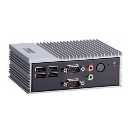
Page 14: I/O Outlets
Series User’s Manual I/O Outlets The following figures show you I/O outlets on front view of the eBOX530-830-FL. Front View Front View drawing 4 x USB 2.0 Reset Button COM1/COM2 Power Button Connectors Connectors Audio Connectors Indicators... - Page 15 Series User’s Manual Rear View Rear View drawing (eBOX530-830-VGA-FL) 5V DC-in RJ45 Ethernet Connector Connector Connector Rear View drawing (eBOX530-830-PGA-FL) 5V DC-in DisplayPort RJ45 Ethernet Connector Connector Connector Introduction...
-
Page 16: Packing List
PGA-US-AT cord, AT mode Fanless embedded system with Intel® ATOM® N2600 eBOX530-830-FL-N2600-1.6G- 1.6GHz dual core processor, DisplayPort, EU power PGA-EU-AT cord, AT mode If you cannot find this package or any items are missing, please contact Axiomtek distributors immediately. Introduction... -
Page 17: Chapter 2 Hardware Installation
Series User’s Manual CHAPTER 2 Hardware Installation The eBOX530-830-FL is convenient for your various hardware configurations, such as Memory Module, HDD (Hard Disk Drive), SSD (Solid State Drive) and CFast card. The chapter 2 will show you how to install the hardware. - Page 18 Series User’s Manual Step 4 Remove the bottom cover Step 5 Loosen screws of HDD bracket Hardware Installation...
- Page 19 Series User’s Manual Step 6 emove the HDD bracket Step 7 Locate the memory module as marked. Hardware Installation...
- Page 20 Series User’s Manual Step 8 Hold one side of the module, and insert the gold colored contact into the socket. Step 9 Push the module down, until it is firmly seated by locking two latches on the sides. NOTE While uninstalling the Memory Module, you need to stretch these two latches aside, and then take the module off the socket.
- Page 21 Series User’s Manual Step 10 Put the HDD bracket back to the system, and fasten screws of HDD bracket Step 11 Put the bottom cover back to the chassis, and fasten all screws. Hardware Installation...
-
Page 22: Sata Hdd
Series User’s Manual SATA HDD Step 1 Turn off the system, and unplug the power cord. Step 2 Turn the system upside down to locate screws at the bottom Step 3 Loosen screws of bottom cover. Hardware Installation... - Page 23 Series User’s Manual Step 4 emove the bottom cover Step 5 oosen screws of HDD bracket Hardware Installation...
- Page 24 Series User’s Manual Step 6 emove the HDD bracket, and pick it up for assemble. Step 7 Assembly the HDD bracket together with the SATA storage. HDD assembly parts include: HDD Bracket x 1 2.5 inch HDD or SSD x 1 ...
- Page 25 Series User’s Manual Step 8 Connect SATA cable and power cable to SATA HDD, and fasten screws of HDD Bracket Step 9 Fasten screws of HDD bracket Hardware Installation...
- Page 26 Series User’s Manual Step 10 Put the bottom cover back to the chassis, and fasten all screws. Hardware Installation...
-
Page 27: Installing Cfast
Series User’s Manual Installing CFast™ Step 1 Turn off the system, and unplug the power cord. Step 2 Turn the system upside down to locate screws at the bottom Step 3 Loosen screws of bottom cover. Hardware Installation... - Page 28 Series User’s Manual Step 4 emove the bottom cover Step 5 oosen screws of HDD bracket Hardware Installation...
- Page 29 Series User’s Manual Step 6 emove the HDD bracket Step 7 Locate the CFast™ slot as marked. Hardware Installation...
- Page 30 Series User’s Manual Step 8 Insert the CFast™ card into the socket until it is firmly seated. Step 9 Put the HDD bracket back to the system, and fasten screws of HDD bracket Hardware Installation...
- Page 31 Series User’s Manual Step 10 Put the bottom cover back to the chassis, and fasten all screws. Hardware Installation...
-
Page 32: Installing Din Mount (Optional)
Series User’s Manual Installing DIN Mount (Optional) The eBOX530-830-FL provides DIN Mount that customers can install as below: Step 1 Prepare DIN Mount assembling components (screws and bracket) ready. MAXIMUM DEPTH OF THE HDD BRACKET: 2.5mm DEPTH 2.5mm MAX. - Page 33 Series User’s Manual Step 2 Assembly the bracket to the system, and fasten screws tight. Hardware Installation...
-
Page 34: Installing Rail Mount (Optional)
Series User’s Manual Installing Rail Mount (Optional) The eBOX530-830-FL provides Rail Mount that customers can install as below: Step 1 Prepare Rail Mount assembling components (screws and bracket) ready. Step 2 Assembly the bracket to the system, and fasten screws tight. -
Page 35: Chapter 3 Jumper Setting & Connector
Series User’s Manual CHAPTER 3 Jumper Setting & Connector Proper jumper settings configure the eBOX530-830-FL to meet your application purpose. We are herewith listing a summary table of all jumpers and default settings for onboard devices, respectively. SBC layout TOP Side Jumper Setting &... - Page 36 Series User’s Manual Bottom Side NOTE: We strongly recommended that you should not modify any unmentioned jumper setting without Axiomtek FAE’s instruction. Any modification without instruction might cause system to become damage. Jumper Setting & Connector...
-
Page 37: Jumper Settings
2 jumper pins to close. And remove jumper clip from 2 jumper pins to open. Below illustration shows how to set up jumper. Properly configure jumper settings on the eBOX530-830-FL to meet your application purpose. We are herewith listing a summary table of all jumpers and default settings for onboard devices, respectively. -
Page 38: Auto Power On
Series User’s Manual 3.2.1 Auto Power On If JP3 is enabled for AC power input, the system will be automatically power on without pressing soft power button. If JP3 is disabled for AC power input, it is necessary to manually press soft power button to power on the system. -
Page 39: Connectors
Connectors Connectors connect the system with other parts/devices. Loose or improper connection might cause problems. Make sure all connectors are properly and firmly connected. Below summary table shows you all connectors on the eBOX530-830-FL. External Connectors Section DC-in Power-Din Connector 3.3.1... -
Page 40: Dc-In Power-Din Connector
Series User’s Manual 3.3.1 DC-in Power-Din Connector The system supports a DC5V power-din connector for system power input. Connect it to the power AC-DC 25W Adapter. Signal 3.3.2 Serial Port Connector The system has four serial ports. COM1 is RS-232/422/485 port, and COM2 is RS-232 port. -
Page 41: Vga Connector
Series User’s Manual 3.3.3 VGA Connector The VGA connector is a slim type 15-pin D-Sub connector which is common for the CRT VGA display. The VGA interface configuration can be configured via the software utility. Signal Signal Signal Green Blue N.C. -
Page 42: Lan Connector (Lan1, Lan2)
Series User’s Manual 3.3.5 LAN Connector (LAN1, LAN2) The RJ-45 connector is for Ethernet. To connect the board to a 1000/100/10 Base-T hub, just plug one end of the cable into connector and connect the other end (phone jack) to a... -
Page 43: Audio Connector
Series User’s Manual 3.3.8 Audio Connector These two audio jacks ideal are for Audio Mic -In and Audio Line-out. Signal Microphone In Line Out 3.3.9 SATA Connector The SATA connector is for high-speed SATA interface ports and they can be connected to hard disk devices. -
Page 44: Sata Power Connector
Series User’s Manual 3.3.10 SATA Power Connector The SATA connector is for high-speed SATA interface ports and they can be connected to hard disk devices. Signal +3.3VDC +3.3VDC +3.3VDC +5VDC +5VDC +5VDC +12VDC +12VDC +12VDC Jumper Setting & Connector... -
Page 45: Cfast™ Socket
The CFast™ card by default identifies itself as C: or D: drive in your PC system. Signal Signal SATA_TX+ SATA_TX- CFAST_LED# SATA_RX- SATA_RX+ +3.3V Level +3.3V Level 3.3.12 DDR3 SODIMM Socket eBOX530-830-FL supports one standard DDR3 204-pin 800/1066 MHz SO-DIMM socket. Jumper Setting & Connector... - Page 46 Series User’s Manual This page is intentionally left blank. Jumper Setting & Connector...
-
Page 47: Chapter 4 Ami Bios Setup Utility
Series User’s Manual CHAPTER 4 AMI BIOS Setup Utility This chapter provides users with detailed description how to set up basic system configuration through the AMI BIOS setup utility. Starting To enter the setup screens, follow the steps below: Turn on the computer and press the <Del>... -
Page 48: Main Menu
Series User’s Manual Main Menu When you first enter the setup utility, you will enter the Main setup screen. You can always return to the Main setup screen by selecting the Main tab. System Time/Date can be set up as described below. -
Page 49: Advanced Menu
Series User’s Manual Advanced Menu Launch PXE OpROM Use this item to enable or disable the boot ROM function of the onboard LAN chip when the system boots up. The Advanced menu also allows users to set configuration of the CPU and other system devices. - Page 50 Series User’s Manual ACPI Settings ACPI Sleep State When the sleep button is pressed, the system will be in the ACPI sleep state. The default is S1 (CPU Stop Clock). AMI BIOS Setup Utility...
- Page 51 Series User’s Manual CPU Configuration This screen shows the CPU Configuration. AMI BIOS Setup Utility...
- Page 52 Series User’s Manual IDE Configuration In the IDE Configuration menu, you can see the currently installed hardware in the SATA ports. During system boot up, the BIOS automatically detects the presence of SATA devices. Configure SATA as Determine how SATA controller(s) operate. Operation mode options are IDE Mode and AHCI (Advanced Host Controller Interface) Mode.
- Page 53 Series User’s Manual F81801 Super IO Configuration You can use this screen to select options for the Super IO Configuration, and change the value of the selected option. A description of the selected item appears on the right side of the screen.
- Page 54 Series User’s Manual Serial Port 2 Configuration Use this option to enable or disable the serial port 2. Serial Port 1 Configuration Use this option to enable or disable and set RS-422/RS-485 mode for the serial port 1.
- Page 55 Series User’s Manual F81801 H/W Monitor This screen monitors hardware health status. This screen displays the temperature of CPU and system voltages (Vcore and +5V). AMI BIOS Setup Utility...
-
Page 56: Chipset Menu
Series User’s Manual Chipset Menu The Chipset menu allows users to change the advanced chipset settings. You can select any of the items in the left frame of the screen to go to the sub menus: ► Host Bridge For items marked with “”, please press <Enter>... - Page 57 Series User’s Manual Host Bridge This screen allows users to configure parameters of Host Bridge chipset. Memory Frequency and Timing Use this item to refer to the information related to memory frequency. Intel IGD Configuration Use this item to configure internal graphics controller.
- Page 58 Series User’s Manual Memory Frequency and Timing This screen shows the memory frequency information. Intel IGD Configuration AMI BIOS Setup Utility...
-
Page 59: Boot Menu
Series User’s Manual Boot Menu The Boot menu allows users to change boot options of the system. Setup Prompt Timeout Number of seconds to wait for setup activation key. 65535(0xFFFF) means indefinite waiting. GateA20 Active If Upon Request is selected, GA20 can be disabled using BIOS services. If Always is selected, disabling G20 is not allowed;... -
Page 60: Security Menu
Series User’s Manual Security Menu The Security menu allows users to change the security settings for the system. Administrator Password This item indicates whether an administrator password has been set (installed or uninstalled). User Password This item indicates whether an user password has been set (installed or uninstalled). -
Page 61: Save & Exit Menu
Series User’s Manual Save & Exit Menu The Save & Exit menu allows users to load your system configuration with optimal or fail-safe default values. Save Changes and Exit When you have completed the system configuration changes, select this option to leave Setup and return to Main Menu. - Page 62 Series User’s Manual Save Changes When you have completed the system configuration changes, select this option to save changes. Select Save Changes from the Save & Exit menu and press <Enter>. Select Yes to save changes. Discard Changes Select this option to quit Setup without making any permanent changes to the system configuration.
-
Page 63: Chapter 5 Drivers Installation
Series User’s Manual CHAPTER 5 Drivers Installation The device drivers are located on the product information CD that comes with the eBOX530- 830-FL Series package. The auto-run function of drivers will guide you to install the utilities and device drivers under Windows system. You can follow the onscreen instructions to install these devices: ... - Page 64 Series User’s Manual 2. A Readme File Information screen appears to show you the system requirements and installation information. Click “Next” to next step. 3. Please wait while setup processes the following operations. Drivers Installation...
- Page 65 Series User’s Manual 4. You are suggested to select “Yes, I want to restart this computer now”. Click “Finish” to complete the setup process and reboot. Drivers Installation...
-
Page 66: Installing Graphics Media Accelerator Driver
Series User’s Manual Installing Graphics Media Accelerator Driver Run the setup.exe program from the driver directory in product information CD. Click “Next” to next step. Drivers Installation... - Page 67 Series User’s Manual ® License Agreement screen appears, please click “Yes” to next step. When Intel A Readme File Information screen appears to show you the system requirements and installation information. Click “Next” to next step. Drivers Installation...
- Page 68 Series User’s Manual Please wait while setup processes the following operations. When the following screen appears, please click “Next”. Drivers Installation...
- Page 69 Series User’s Manual You are suggested to select “Yes, I want to restart this computer now”. Click “Finish” to complete the setup process and reboot. NOTE After the computer reboots, the display is in extended mode. Please click hot key <Ctrl+Alt+F1>...
-
Page 70: Installing Ethernet Driver
Series User’s Manual Installing Ethernet Driver Unzip PROWin32 for ethernet driver from the driver directory in product information CD. Click “Next” to start the installation. Drivers Installation... - Page 71 Series User’s Manual When the following screen appears, please select the program features you want to install. Click “Next” to continue. Click “Finish” to complete the installation. Drivers Installation...
-
Page 72: Installing Audio Driver
Series User’s Manual Installing Audio Driver Run the setup.exe for audio from the driver directory in product information CD. Click “Next” to continue. You are suggested to select “Yes, I want to restart my computer now”. Click “Finish” to complete the setup process and reboot. -
Page 73: Appendix A Watchdog Timer
Series User’s Manual APPENDIX A Watchdog Timer About Watchdog Timer Software stability is major issue in most application. Some embedded systems are not watched by human for 24 hours. It is usually too slow to wait for someone to reboot when computer hangs. -
Page 74: Sample Program
Series User’s Manual Sample Program Assembly sample code : ;Enable WDT: dx,2Eh al,87 ;Un-lock super I/O dx,al dx,al ;Select Logic device: dx,2Eh al,07h dx,al dx,2Fh al,08h dx,al ;Activate WDT: dx,2Eh al,30h dx,al dx,2Fh al,01h dx,al ;Set Second or Minute :... - Page 75 Series User’s Manual al,0F6h dx,al dx,2Fh al,Mh ;M=00h,01h,...FFh (hex),Value=0 to 255 Note dx,al ;(see below ;Disable WDT: dx,2Eh al,30h dx,al dx,2Fh al,00h ;Can be disabled at any time dx,al Note: If N=00h, the time base is set to second.
- Page 76 Series User’s Manual This page is intentionally left blank. Watchdog Timer...
Need help?
Do you have a question about the eBOX530-830-FL and is the answer not in the manual?
Questions and answers