
Related Manuals for AXIOMTEK SDM500L


Summary of Contents for AXIOMTEK SDM500L
- Page 1 SDM500L ® Intel Smart Display Module (SDM-L) with Intel® Core™ Whiskey Lake U Processor User’s Manual...
-
Page 2: Disclaimers
Axiomtek does not make any commitment to update the information in this manual. Axiomtek reserves the right to change or revise this document and/or product at any time without notice. No part of this document may be reproduced, stored in a retrieval system, or transmitted, in any form or by any means, electronic, mechanical, photocopying, recording, or otherwise, without the prior written permission of Axiomtek Co., Ltd. -
Page 3: Esd Precautions
When handling modules and components, wear a wrist-grounding strap, available from most electronic component stores. Trademarks Acknowledgments Axiomtek is a trademark of Axiomtek Co., Ltd. ® Windows is a trademark of Microsoft Corporation. AMI is a trademark of American Megatrend Inc. -
Page 4: Table Of Contents
Table of Contents Disclaimers ..................... ii ESD Precautions ................... iii Chapter 1 Introduction ..........1 Features ....................1 Specifications ..................2 Utilities Supported ................3 Chapter 2 Module and Pin Assignments ....5 Module Dimensions and Fixing Holes ..........5 Module Layout .................. - Page 5 Chapter 4 AMI BIOS Setup Utility ......25 Starting ....................25 Navigation Keys ................25 Main Menu ..................27 Advanced Menu ................. 28 Chipset Menu ..................34 Security Menu ..................36 Boot Menu ..................37 Save & Exit Menu ................38 Appendix A Watchdog Timer ........
- Page 6 This page is intentionally left blank.
-
Page 7: Chapter 1 Introduction
USB 3.0, HDMI 1.4, DisplayPort 1.2, Serial TX/RX and I C. In addition, for maximum integration flexibility, the SDM500L can be built in or externally plugged into a display, which allows this cost-effective smart display module to fit into even the sleekest all-in-one designs. -
Page 8: Specifications
® SDM500L Intel Smart Display Module (SDM-L) Specifications ® ® Intel Core i3/i5/i7 Celeron processor ® Core™ i5-8265U Processor Intel ® Core™ i3-8145U Processor Intel ® ® Intel Celeron Processor 4305UE BIOS American Megatrends Inc. BIOS. -
Page 9: Utilities Supported
® SDM500L Intel Smart Display Module (SDM-L) Utilities Supported Chipset driver Graphics driver TXE driver Serial IO driver Ethernet utility and driver All specifications and images are subject to change without notice. Note Introduction... - Page 10 ® SDM500L Intel Smart Display Module (SDM-L) This page is intentionally left blank. Introduction...
-
Page 11: Module And Pin Assignments
® SDM500L Intel Smart Display Module (SDM-L) Chapter 2 Module and Pin Assignments Module Dimensions and Fixing Holes Top View Hardware Description... - Page 12 ® SDM500L Intel Smart Display Module (SDM-L) Bottom View Side View Hardware Description...
-
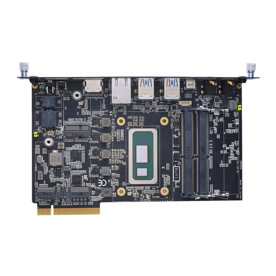
Page 13: Module Layout
® SDM500L Intel Smart Display Module (SDM-L) Module Layout Top View Bottom View Hardware Description... -
Page 14: Jumper Settings
® SDM500L Intel Smart Display Module (SDM-L) Jumper Settings A jumper is a small component consisting of a set of jumper pins with a jumper clip. Place a jumper clip on two jumper pins to close; remove a jumper clip from two jumper pins to open. -
Page 15: Connectors
® SDM500L Intel Smart Display Module (SDM-L) Connectors Signals go to the other parts of the system through connectors. Loose or improper connection might cause problems. Please make sure all connectors are properly and firmly connected. Here is a table summarizing the connectors on the hardware. -
Page 16: B Key 2242 Socket (Cn2)
® SDM500L Intel Smart Display Module (SDM-L) 2.4.2 M.2 B Key 2242 Socket (CN2) The module has one M.2 E Key 2230 socket on the top side supporting PCI Express x1 and USB 2.0. Signal Signal CONFIG_3 +3.3V +3.3V FULL_CARD_POWER_OFF... -
Page 17: M Key 2280 Socket (Cn3)
® SDM500L Intel Smart Display Module (SDM-L) 2.4.3 M.2 M Key 2280 Socket (CN3) This system has one M.2 M key socket for inserting the M.2 2280 NVMe / SATA SSD module. Signal Signal +3.3V +3.3V PERn3 PERp3 LED1# PETn3 +3.3V... -
Page 18: Usb 3.1 Gen1 Port Stacks (Cn4 And Cn5)
® SDM500L Intel Smart Display Module (SDM-L) 2.4.4 USB 3.1 Gen1 Port Stacks (CN4 and CN5) The Universal Serial Bus (compliant with USB 3.1 Gen1 (5Gb/s)) connectors are on the rear I/O side. It is commonly used for installing USB peripherals such as a keyboard, mouse, scanner, etc. -
Page 19: Audio Jack Line-Out Connector (Cn7)
® SDM500L Intel Smart Display Module (SDM-L) 2.4.6 Audio Jack Line-out Connector (CN7) The system provides one HD audio jack Line_out connector. Setting LINEOUT_L LINEOUT_R 2.4.7 Reset button (CN8) The Reset button allows users to reset the system when an abnormal situation occurs during system operation. -
Page 20: E Key Connector (Ngff1)
® SDM500L Intel Smart Display Module (SDM-L) 2.4.10 M.2 E KEY Connector (NGFF1) The system has one M.2 E Key 2230 socket on the top side supporting PCI Express x1 / CNVi and USB 2.0. Signal Signal +3.3V USB_D+ +3.3V... -
Page 21: Sdm Edge Connector (J1)
® SDM500L Intel Smart Display Module (SDM-L) 2.4.12 SDM Edge Connector (J1) The following table shows pin assignments of the 98-pin SDM PCIEx8 edge connector. Side B (Top) Side A (Bottom) +12V +12V +12V +12V +3.3VSB +12V PWRBTN# PWRGD# RESET#... - Page 22 ® SDM500L Intel Smart Display Module (SDM-L) This page is intentionally left blank. Hardware Description...
-
Page 23: Chapter 3 Hardware Description
Make sure all correct settings are arranged for the installed microprocessor to prevent the CPU from damage. BIOS The SDM500L uses AMI Plug and Play BIOS with a single 256Mbit SPI Flash. System Memory Two 260-pin DDR4-2400 SO-DIMM slots, up to 32GB at the maximum. -
Page 24: I/O Port Address Map
® SDM500L Intel Smart Display Module (SDM-L) I/O Port Address Map The I/O port address mapping list is shown as follows: Hardware Description... -
Page 25: Interrupt Controller (Irq) Map
® SDM500L Intel Smart Display Module (SDM-L) Interrupt Controller (IRQ) Map The interrupt controller (IRQ) mapping list is shown as follows: Hardware Description... - Page 26 ® SDM500L Intel Smart Display Module (SDM-L) Hardware Description...
- Page 27 ® SDM500L Intel Smart Display Module (SDM-L) Hardware Description...
- Page 28 ® SDM500L Intel Smart Display Module (SDM-L) Hardware Description...
- Page 29 ® SDM500L Intel Smart Display Module (SDM-L) Hardware Description...
-
Page 30: Memory Map
® SDM500L Intel Smart Display Module (SDM-L) Memory Map The memory mapping list is shown as follows: Hardware Description... -
Page 31: Ami Bios Setup Utility
® SDM500L Intel Smart Display Module (SDM-L) Chapter 4 AMI BIOS Setup Utility The AMI UEFI BIOS provides users with a built-in setup program to modify basic system configuration. All configured parameters are stored in a flash chip to save the setup information whenever the power is turned off. - Page 32 ® SDM500L Intel Smart Display Module (SDM-L) Hot Keys Description Left/Right The Left and Right <Arrow> keys allow you to select a setup screen. The Up and Down <Arrow> keys allow you to select a setup screen or Up/Down sub-screen.
-
Page 33: Main Menu
® SDM500L Intel Smart Display Module (SDM-L) Main Menu The Main BIOS setup screen is the first screen you see when entering the setup utility. You can always return to the Main BIOS setup screen by selecting the Main tab. System Time/Date can be set up as described below. -
Page 34: Advanced Menu
® SDM500L Intel Smart Display Module (SDM-L) Advanced Menu The Advanced menu also allows users to set configuration of the CPU and other system devices. You can select any of the items in the left frame of the screen to go to the sub menus: ►... - Page 35 ® SDM500L Intel Smart Display Module (SDM-L) ACPI Settings You can use this menu to select options for system ACPI configuration, and then change the value of the selected option. A description of the selected item appears on the right side of the screen.
- Page 36 ® SDM500L Intel Smart Display Module (SDM-L) CPU Configuration This screen shows the CPU Configuration, and you can change the value of the selected option. CPU Power Management Configuration Intel® SpeedStep™ Enable or disable Intel SpeedStep mode. The default setting is Enabled.
- Page 37 ® SDM500L Intel Smart Display Module (SDM-L) Network Stack Configuration Network Stack Enable or disable UEFI Network stack. The default setting is disabled. CSM (Compatibility Support Module) Configuration CSM Support Enable or disable CSM support. The default setting is Enabled.
- Page 38 ® SDM500L Intel Smart Display Module (SDM-L) Hardware Monitor This menu allows the user to monitor hardware health status as well as enable or disable the Smart Fan function. This screen displays the temperature of system memory area (System temperature1), power-in area (System temperature2) and CPU, fan speed, system voltages (VCORE, +3.3V, and +5V).
- Page 39 ® SDM500L Intel Smart Display Module (SDM-L) PCH-FW configuration This menu shows the ME firmware information. RTC Wake setting This menu allows the user to enable the system to wake on an alarm event using a real-time clock (RTC).
-
Page 40: Chipset Menu
® SDM500L Intel Smart Display Module (SDM-L) Chipset Menu The Chipset menu allows users to change the advanced chipset settings. You can select any of the items in the left frame of the screen to go to the sub menus: For items marked with “”, please press <Enter>... - Page 41 ® SDM500L Intel Smart Display Module (SDM-L) SATA and RST Configuration In the SATA Configuration menu, you can see the currently installed hardware in the SATA ports. During system boot up, the BIOS automatically detects the presence of SATA devices.
-
Page 42: Security Menu
® SDM500L Intel Smart Display Module (SDM-L) Security Menu The Security menu allows users to enhance system security by creating an administrator password to limit system access. Administrator Password Set up an administrator password. AMI BIOS Setup Utility... -
Page 43: Boot Menu
® SDM500L Intel Smart Display Module (SDM-L) Boot Menu The Boot menu allows users to change boot options of the system. Setup Prompt Timeout Set up number of seconds to wait for the setup activation key. 65535(0xFFFF) means indefinite waiting. -
Page 44: Save & Exit Menu
® SDM500L Intel Smart Display Module (SDM-L) Save & Exit Menu The Save & Exit menu allows users to load system configurations with optimal or fail-safe default values. Save Changes and Exit When you have completed the system configuration changes, select this option to leave Setup and continue to boot to operating system. - Page 45 ® SDM500L Intel Smart Display Module (SDM-L) Discard Changes Select this option to quit Setup without making any permanent changes to the system configuration. Select Discard Changes from the Save & Exit menu and press <Enter>. Select Yes to discard changes.
- Page 46 ® SDM500L Intel Smart Display Module (SDM-L) This page is intentionally left blank. AMI BIOS Setup Utility...
-
Page 47: Appendix A Watchdog Timer
® SDM500L Intel Smart Display Module (SDM-L) Appendix A Watchdog Timer A.1 About Watchdog Timer Software stability is a major issue in most application. Some embedded systems are not watched by human for 24 hours. It is usually too slow to wait for someone to reboot when computer hangs. - Page 48 ® SDM500L Intel Smart Display Module (SDM-L) Note: If N=00h, the time base is set to second. M = time value 00h: Time-out Disable 01h: Time-out occurs after 1 second 02h: Time-out occurs after 2 seconds 03h: Time-out occurs after 3 seconds FFh: Time-out occurs after 255 seconds If N=08h, the time base is set to minute.
Need help?
Do you have a question about the SDM500L and is the answer not in the manual?
Questions and answers