Sign In
Upload
Manuals
Brands
IEI Technology Manuals
Desktop
ECN-780-Q67
IEI Technology ECN-780-Q67 Manuals
Manuals and User Guides for IEI Technology ECN-780-Q67. We have
1
IEI Technology ECN-780-Q67 manual available for free PDF download: User Manual
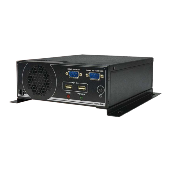
IEI Technology ECN-780-Q67 User Manual (184 pages)
Embedded System with 2nd Gen Intel Core i7/i5/i3 Des ktop Processors, DVI, HDMI, VGA, GbE, Two USB 3.0, Two USB 2.0, Three COM and RoHS Compliant
Brand:
IEI Technology
| Category:
Desktop
| Size: 7 MB
Table of Contents
Table of Contents
4
Introduction
14
Overview
15
Model Variations
15
Features
15
Figure 1-1: ECN-780-Q67
15
Table 1-1: Model Variations
15
Technical Specifications
16
Front Panel
18
Rear Panel
18
Figure 1-2: ECN-780-Q67 Front Panel
18
Table 1-2: Technical Specifications
18
Figure 1-3: ECN-780-Q67 Rear Panel
19
Dimensions
20
Figure 1-4: Physical Dimensions (MM)
20
Unpacking
21
Anti - Static Precautions
22
Unpacking Precautions
22
Unpacking Checklist
23
Table 2-1: Package List Contents
24
Installation
25
Installation Precautions
26
Installation and Configuration Steps
26
Hard Disk Drive (Hdd) Installation
26
Figure 3-1: Retention Screws Removal
27
Figure 3-2: HDD Bracket
27
At/Atx Mode Selection
28
Figure 3-3: HDD Retention Screws
28
AT Power Mode
29
ATX Power Mode
29
Figure 3-4: AT/ATX Switch Location
29
Reset the System
30
Powering O N /Off the System
30
Figure 3-5: Reset Button Location
30
Mount the System
31
Figure 3-6: Power Button Location
31
Figure 3-7: Mounting Screw Holes
31
Mounting the System with Mounting Brackets
32
Figure 3-8: Mounting Bracket Retention Screws
32
External Peripheral Interface Connectors
33
Audio Connection
34
Figure 3-9: Peripheral Connectors (Front Panel)
34
Figure 3-10: Peripheral Connectors (Rear Panel)
34
DVI Display Device Connection
35
Figure 3-11: Audio Connector
35
HDMI Device Connection
36
Figure 3-12: DVI Connector
36
LAN Connection
37
Figure 3-13: HDMI Connection
37
Serial Port Connection
38
Figure 3-14: LAN Connection
38
USB Device Connection
39
Figure 3-15: DB-9 Serial Port Connector
39
VGA Monitor Connection
40
Figure 3-16: USB Device Connection
40
Intel ® Amt Setup Procedure
41
Figure 3-17: VGA Connector
41
System Motherboard
43
Overview
44
Layout
44
Figure 4-1: Connector and Jumper Locations (Front Side)
44
Motherboard Dimensions
45
Figure 4-2: Connector and Jumper Locations (Rear Side)
45
Figure 4-3: Motherboard Dimensions (Front Side) (MM)
45
Peripheral Interface Connectors
46
Figure 4-4: Motherboard Dimensions (Rear Side) (MM)
46
Internal Peripheral Connectors
47
Battery Connector
47
Table 4-1: Peripheral Interface Connectors
47
BIOS Programming Connector
48
Figure 4-5: Battery Connector Location
48
Table 4-2: Battery Connector Pinouts
48
Digital I/O Connector
49
Figure 4-6: BIOS Programming Connector Location
49
Table 4-3: BIOS Programming Connector Pinouts
49
EC Programming Connector
50
Figure 4-7: Digital I/O Connector Location
50
Table 4-4: Digital I/O Connector Pinouts
50
Fan Connector (System)
51
Figure 4-8: EC Programming Connector Location
51
Table 4-5: EC Programming Connector Pinouts
51
Keyboard/Mouse Connector
52
Figure 4-9: System Fan Connector Location
52
Table 4-6: System Fan Connector Pinouts
52
LED Module Connector
53
Figure 4-10: Keyboard/Mouse Connector Location
53
Table 4-7: Keyboard/Mouse Connector Pinouts
53
Pcie Mini Card Slot
54
Figure 4-11: LED Module Connector Location
54
Table 4-8: LED Module Connector Pinouts
54
Power Connector
55
Figure 4-12: Pcie Mini Card Slot Location
55
Serial Port Connectors
56
Figure 4-13: Power Connector Location
56
Table 4-9: Power Connector Pinouts
56
RS-422/485 Serial Port Connector
57
Figure 4-14: RS-232 Serial Port Connector Location
57
Figure 4-15: RS-232 Serial Port Connector Location
57
Table 4-10: Serial Port Connector Pinouts (COM1, COM2, COM3, COM4 )
57
SATA Drive Connectors
58
Figure 4-16: RS-422/485 Serial Port Connector Location
58
Table 4-11: RS-422/485 Serial Port Connector Pinouts
58
SATA Power Connectors
59
Figure 4-17: SATA Drive Connector Locations
59
Smbus Connector
60
Figure 4-18: SATA Power Connector Locations
60
Table 4-12: SATA Power Connector Pinouts
60
SO-DIMM Connector
61
Figure 4-19: Smbus Connector Location
61
Table 4-13: Smbus Connector Pinouts
61
K Type Thermocouple Connectors
62
Figure 4-20: SO-DIMM Connector Locations
62
Figure 4-21: Type K Thermocouple Connector Locations
62
TPM Connector
63
Figure 4-22: TPM Connector Location
63
Table 4-14: Type K Thermocouple Connector Pinouts
63
USB 2.0 Connectors
64
Figure 4-23: USB Connector Locations
64
Table 4-15: TPM Connector Pinouts
64
VGA Connector
65
Figure 4-24: VGA Connector Location
65
Table 4-16: USB Port Connector Pinouts
65
Table 4-17: VGA Connector Pinouts
65
Jumper Settings
66
Clear CMOS
66
Table 4-18: Jumpers
66
Flash Descriptor Security Override
67
Figure 4-25: Clear CMOS Jumper Location
67
Table 4-19: Clear CMOS Jumper Settings
67
Table 4-20: Flash Descriptor Security Override Jumper Settings
67
Figure 4-26: Flash Descriptor Security Override Jumper Location
68
Bios
69
Introduction
70
Starting Setup
70
Using Setup
70
Getting Help
71
Unable to Reboot after Configuration Changes
71
BIOS Menu Bar
71
Table 5-1: BIOS Navigation Keys
71
Main
72
Advanced
73
ACPI Configuration
74
RTC Wake Settings
75
Trusted Computing
76
CPU Configuration
77
CPU Information
78
SATA Configuration
79
Intel TXT (LT) Configuration
80
USB Configuration
81
F81866 Super IO Configuration
82
Serial Port N Configuration
83
F81866 H/W Monitor
87
Smart Fan Mode Configuration
89
Serial Port Console Redirection
91
Console Redirection Settings
92
I E I Feature
94
Chipset
95
Northbridge Configuration
96
Southbridge Configuration
97
Intel IGD SWSCI Opregion
99
ME Subsystem
100
Boot
101
Security
103
Exit
104
Software Drivers
106
Available Software Drivers
107
Starting the Driver Program
107
Chipset Driver Installation
108
Figure 6-1: Drivers
108
Figure 6-2: Chipset Driver Screen
109
Figure 6-3: Chipset Driver Welcome Screen
109
Figure 6-4: Chipset Driver License Agreement
110
Figure 6-5: Chipset Driver Read Me File
111
Figure 6-6: Chipset Driver Setup Operations
111
Graphics Driver Installation
112
Figure 6-7: Chipset Driver Installation Finish Screen
112
Figure 6-8: Graphics Driver Read Me File
113
Figure 6-9: Graphics Driver Setup Files Extracted
113
Figure 6-10: Graphics Driver Welcome Screen
114
Figure 6-11: Graphics Driver License Agreement
114
Figure 6-12: Graphics Driver Read Me File
115
Figure 6-13: Graphics Driver Setup Operations
115
Lan Driver Installation
116
Figure 6-14: Graphics Driver Installation Finish Screen
116
Figure 6-15: Intel® Network Connection Menu
117
Figure 6-16: LAN Driver Welcome Screen
117
Figure 6-17: LAN Driver License Agreement
118
Figure 6-18: LAN Driver Setup Options
118
Figure 6-19: LAN Driver Installation
119
Figure 6-20: LAN Driver Installation Complete
119
Audio Driver Installation
120
Figure 6-21: Audio Driver Welcome Screen
120
Figure 6-22: Audio Driver Installation
121
Figure 6-23: Audio Driver Installation Complete
121
Usb 3.0 Driver Installation
122
Figure 6-24: USB 3.0 Driver Welcome Screen
122
Figure 6-25: USB 3.0 Driver Choose Install Location
123
Figure 6-26: USB 3.0 Driver Choose Install Location
123
Intel ® Management Engine Components Installation
124
Figure 6-27: USB 3.0 Driver Installation Complete
124
Figure 6-28: Intel® ME Driver Welcome Screen
125
Figure 6-29: Intel® ME Driver License Agreement
126
Figure 6-30: Intel® ME Driver Read Me File
126
Figure 6-31: Intel® ME Driver Setup Operations
127
Figure 6-32: Intel® ME Driver Installation Finish Screen
128
A Safety Precautions
129
Safety Precautions
130
General Safety Precautions
130
Anti-Static Precautions
131
Product Disposal
132
Maintenance and Cleaning Precautions
132
Maintenance and Cleaning
132
Cleaning Tools
133
B Bios Menu Options
134
C One Key Recovery
137
One Key Recovery Introduction
138
Figure C-1: IEI One Key Recovery Tool Menu
138
System Requirement
139
Supported Operating System
140
Setup Procedure for Windows
141
Hardware and BIOS Setup
142
Create Partitions
142
Figure C-2: Launching the Recovery Tool
143
Figure C-3: Recovery Tool Setup Menu
143
Figure C-4: Command Prompt
144
Figure C-5: Partition Creation Commands
145
Install Operating System, Drivers and Applications
146
Building the Recovery Partition
147
Figure C-6: Launching the Recovery Tool
147
Figure C-7: Manual Recovery Environment for Windows
147
Figure C-8: Building the Recovery Partition
148
Figure C-9: Press any Key to Continue
148
Create Factory Default Image
149
Figure C-10: Press F3 to Boot into Recovery Mode
149
Figure C-11: Recovery Tool Menu
149
Figure C-12: about Symantec Ghost Window
150
Figure C-13: Symantec Ghost Path
150
Figure C-14: Select a Local Source Drive
151
Figure C-15: Select a Source Partition from Basic Drive
151
Figure C-16: File Name to Copy Image to
152
Figure C-17: Compress Image
152
Figure C-18: Image Creation Confirmation
153
Figure C-19: Image Creation Complete
153
Figure C-20: Image Creation Complete
153
Auto Recovery Setup Procedure
154
Figure C-21: Press any Key to Continue
154
Figure C-22: Auto Recovery Utility
155
Figure C-23: Launching the Recovery Tool
155
Figure C-24: Auto Recovery Environment for Windows
155
Figure C-25: Building the Auto Recovery Partition
156
Figure C-26: Factory Default Image Confirmation
156
Figure C-27: Image Creation Complete
157
Figure C-28: Press any Key to Continue
157
Setup Procedure for Linux
158
Figure C-29: Partitions for Linux
159
Figure C-30: Manual Recovery Environment for Linux
160
Figure C-31: Access Menu.lst in Linux (Text Mode)
161
Figure C-32: Recovery Tool Menu
161
Recovery Tool Functions
162
Figure C-33: Recovery Tool Main Menu
162
Factory Restore
163
Figure C-34: Restore Factory Default
163
Backup System
164
Figure C-35: Recovery Complete Window
164
Figure C-36: Backup System
164
Restore Your Last Backup
165
Figure C-37: System Backup Complete Window
165
Figure C-38: Restore Backup
165
Manual
166
Figure C-39: Restore System Backup Complete Window
166
Figure C-40: Symantec Ghost Window
166
Restore Systems from a Linux Server through Lan
167
Configure DHCP Server Settings
168
Configure TFTP Settings
169
Configure One Key Recovery Server Settings
170
Start the DHCP, TFTP and HTTP
171
Create Shared Directory
171
Setup a Client System for Auto Recovery
172
Other Information
175
Using AHCI Mode or Ali M5283 / VIA VT6421A Controller
175
System Memory Requirement
177
D Watchdog Timer
178
E Hazardous Materials Disclosure
181
Hazardous Materials Disclosure Table for Ipb Products Certified as R Ohs Compliant under 2002/95/Ec Without Mercury
182
Advertisement
Advertisement
Related Products
IEI Technology ECK-3692
IEI Technology ECN-581A-QM57
IEI Technology ECW-281BB6
IEI Technology ECW-281B-BTi
IEI Technology ECK-1000 Series
IEI Technology ECK-1000-9453
IEI Technology ECK-1000-690S1
IEI Technology ECN-360A-HM65
IEI Technology ECN-360A-HM65/4G-R10
IEI Technology ECN-360AW-HM65/4G-R10
IEI Technology Categories
Motherboard
Touch Panel
Computer Hardware
Single board computers
Desktop
More IEI Technology Manuals
Login
Sign In
OR
Sign in with Facebook
Sign in with Google
Upload manual
Upload from disk
Upload from URL