Table of Contents
Advertisement
Quick Links
Advertisement
Table of Contents

Related Manuals for CAME ENTROTEC PRO-DC4


Summary of Contents for CAME ENTROTEC PRO-DC4
- Page 1 PRO-DC4 installation & SETUP guide Issue 001 - December 2022 came.com/entrotec...
- Page 2 Warranty and Support CAME Entrotec systems are renowned for their reliability and have a 2-year warranty on all CAME Entrotec manufactured products as standard. This warranty does not cover water damage, vandalism, mains electrical faults, lightning strikes, damage caused by miswiring or cable faults.
-
Page 3: Table Of Contents
Contents Contents Cable Specification ......................4 Typical Configuration ....................4 Overview ..........................5 Power Supply ........................6 Mains Supply Connections ..................6 Secure Lock Relay ....................... 7 Input + Exit Switch Connections ................. 7 Fail Open Lock Connection ..................7 Fail Closed Lock Connection .................. -
Page 4: Cable Specification
Cable Specification 1 Cable Specification The cabling system is based on Unshielded Twisted Pair Category 5e (Cat5e) or Category 6 (Cat6). The cable must be annealed pure copper, meeting or exceeding the requirements defined in the standard ANSI/TIA 568 C.2. Failure to comply with this cable specification may result in erratic operation of equipment. -
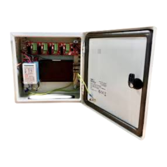
Page 5: Overview
Overview 2 Overview FIGURE 2-1 Item Connection Detail Power Supply Unit (PSU) Section 3 - Page 6 Secure Lock Relay Section 4 - Page 7 Network Switch Section 5.2 - Page 9... -
Page 6: Power Supply
Power Supply 3 Power Supply Fused Terminal Block Earth Point Pre-Wired 12V to Internal Devices Backup Battery Connections for Sealed Lead Acid Battery Output Voltage Adjustment SYSTEM VOLTAGE 13.8VDC � � � Always test the output voltage. Only adjust if required. FIGURE 3 Mains Supply Connections Fuse Holder... -
Page 7: Secure Lock Relay
Secure Lock Relay 4 Secure Lock Relay FIGURE 4 - SLR WITH FACTORY FITTED CONNECTIONS DC IN - Power Input Fail Open Lock Connection Connection for fail open locks (power to Channel 1 hold), e.g. magnetic locks. Channel 2 Channel 3 Channel 4 PL2 - Watchdog Link (bottom pins) and Heartbeat LED... -
Page 8: Lock Suppression
� CAME Entrotec supply 1N4007 diodes. FIGURE 4-5 - 1N4007 DIODE FITTED AT LOCK CAME Entrotec recommend locks with built in suppression. If such a lock is not being used it is ESSENTIAL to fit suitable suppression, as close to the lock as possible. This... -
Page 9: Connections At Panel
Call Panel connections Connections at Panel FIGURE 5-2 Connection Cable Type Detail RS485 from Call Panel 1 Pair UTP - RS485A + RS485B Splitter 1x Cat5e or Cat6 12VDC from Call Panel 1 Pair UTP - 12v (White) Splitter 2 Pair UTP - 0v (Black) Ethernet to Network Switch 1x Cat5e or Cat6 RJ45 - T568B... -
Page 10: Pairing Secure Lock Relay With Call Panel
Pairing Secure Lock Relay with Call Panel 6 Pairing Secure Lock Relay with Call Panel Confirm Door No. of Call Panel Connect a laptop or PC to the same network as the Call Panel. Use a web browser and enter the IP address of the Call Panel in to the address bar. iii. -
Page 11: Device List
Device List 7 Device List Block IP Address SIP ID Type Description 192.168.1.111 8001 Call Panel Ashwood Court, Front Door... - Page 12 © PRODCGUIDE0322 - 2022 - EN YOU MAY NOT EVEN PARTIALLY REPRODUCE THIS DOCUMENT THE DATA AND INFORMATION SHOWN IN THIS CATALOGUE ARE SUBJECT TO CHANGE WITHOUT OBLIGATION TO GIVE PRIOR NOTICE BY CAME S. P.A, E&OE CAME S. p.A.
Need help?
Do you have a question about the ENTROTEC PRO-DC4 and is the answer not in the manual?
Questions and answers