Do you have a question about the AGT A200 and is the answer not in the manual?
Questions and answers
Francesco
March 14, 2025
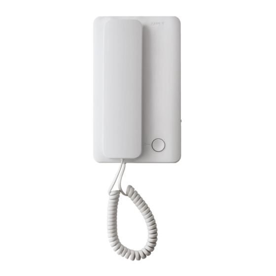
Salve. Dovrei sostituire la cornetta del mio citofono un BTPYC200_200A. Oltre al pulsante di apertura porta, nella mia cornetta ci sono 2 pulsanti aggiuntivi che utilizzo per comandi ausiliari. La cornetta AGT-A200 è compatibile **** il mio sistema? C'è la possibilità di aggiungere pulsanti aggiuntivi? Grazie.
1 comments:
Mr. Anderson
May 14, 2025
The context does not mention compatibility with the BTPYC200_200A system, so compatibility cannot be confirmed. However, the AGT A200 intercom allows installation of up to 4 additional buttons using the common call micro-contacts.


Need help?
Do you have a question about the AGT A200 and is the answer not in the manual?
Questions and answers
Salve. Dovrei sostituire la cornetta del mio citofono un BTPYC200_200A. Oltre al pulsante di apertura porta, nella mia cornetta ci sono 2 pulsanti aggiuntivi che utilizzo per comandi ausiliari. La cornetta AGT-A200 è compatibile **** il mio sistema? C'è la possibilità di aggiungere pulsanti aggiuntivi? Grazie.
The context does not mention compatibility with the BTPYC200_200A system, so compatibility cannot be confirmed. However, the AGT A200 intercom allows installation of up to 4 additional buttons using the common call micro-contacts.
This answer is automatically generated