Table of Contents
Advertisement
Quick Links
Advertisement
Table of Contents

Related Manuals for ACME Diamonds LS-1010 RGB


Summary of Contents for ACME Diamonds LS-1010 RGB
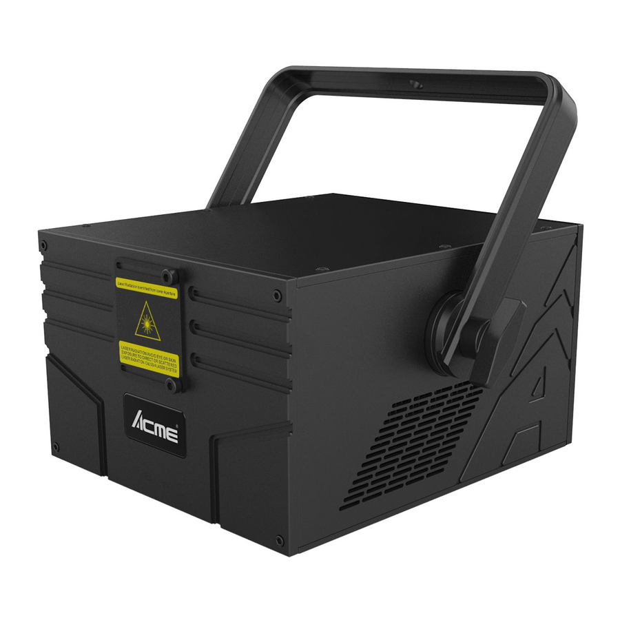
- Page 1 Diamonds LS‐1010 RGB User Manual Please read the instruction carefully before use...
-
Page 2: Table Of Contents
MENU 1. Safety Instructions ........................... 2 2. Technical Specifications ........................ 3 3. Installation ............................ 3 4. How to Set the Unit ......................... 4 4.1 Control Panel .......................... 4 4.2 Main Function .......................... 4 5. How to Control the Unit ........................ 6 6. DMX512 Configuration ........................ 6 7. DMX512 Connections ........................ 8 8. Troubleshooting .......................... 9 9. Fixture Cleaning .......................... 10 ... -
Page 3: Safety Instructions
1. Safety Instructions Please read carefully the instruction, which includes important information about the installation, usage and maintenance. WARNING Please keep this User Guide for future consultation. If you sell the unit to another user, be sure that they also receive this instruction booklet. Unpack and check carefully there is no transportation damage before using the unit. Before operating, ensure that the voltage and frequency of power supply match the power requirements of the unit. It’s important to ground the yellow/green conductor to earth in order to avoid electric shock. The unit is for indoor use only. Use only in a dry location. The unit must be installed in a location with adequate ventilation, at least 50cm from adjacent surfaces. Be sure that no ventilation slots are blocked. ... -
Page 4: Technical Specifications
DO NOT touch any wire during operation as high voltage might be causing electric shock. 2. Technical Specifications Four control modes: ILDA / DMX/Sound Active/Auto Play; Voltage: AC100V~240V,50/60Hz Laser power consumption: 10W Power consumption: 102W Scanning system: 40K Scanner ... -
Page 5: How To Set The Unit
4. How to Set the Unit 4.1 Control Panel ○ ○ 1 OLED Display 2 Knob ○ ○ 3 SD Card Port 4 ... - Page 6 DMX Functions Press the knob when the DMX FUNCTIONS show on the display, use the knob to select DMX Address, DMX state or Exit. Enter DMX Address, turn the knob to change the address, press the knob to confirm. Enter DMX State, select the HOLD/Black Out/Show Mode, when select Show Mode, the unit preference to sound active. If the sound active function is closed, the unit will auto run built‐in show. ILDA signal control prior to DMX signal control. Press EXIT to back to the menu. Show Functions Press the knob when the Show Functions show on the display, use the knob to select Show or Exit. Enter Show, turn the knob to select show 0 to show 9, press the knob to confirm. (Show function only is valid when select Show Mode in DMX functions.) SD card show prior to built‐in show. Press EXIT to back to the menu. Sound Functions Press the knob when the Sound Functions show on the display, use the knob to select Sound Mode or Sound Sense or Exit. Enter Sound Mode, use the knob to select On or off, press the knob to confirm. ILDA signal and DMX signal control prior to sound active mode. Press EXIT to back to the menu. ...
-
Page 7: How To Control The Unit
SD Functions Press the knob when the SD Functions show on the display, use the knob to select SD Mode, SD File or Exit. Enter SD Mode, use the knob to select ILD Show, PRG Show or No SD, press the knob to confirm. Enter SD File, select the file or folder, press the knob to confirm. Press EXIT to back to the menu. Figure Functions Press the knob when the Figure Functions show on the display, use the knob to select Size, Phase Set or Exit. Enter Size, use the knob to select figure size from 10 to 100, press the knob to confirm. Enter Phase Set, set the positon of the figure. Press EXIT to back to the menu. Fixture Functions Press the knob when the Fixture Functions show on the display, use the knob to select Back Lights, Fixture Hours, Defaults, Version or Exit. Enter Back lights, use the knob to select on or off, press the knob to confirm. Enter Fixture Hours, the running time of the unit will be show on the display. Enter Defaults, use the knob to select Yes or no to restore factory settings or not. Enter Version, the version of the software will be show on the display. Press EXIT to back to the menu. 5. How to Control the Unit 1. By ILDA; Connect the unit to the computer with ILDA wire and control the software by computer laser; Priority to control the unit: ILDA﹥DMX﹥Sound active﹥Auto play 2. By universal DMX controller; Set the DMX address, the unit will be ready to receive DMX signal. 3. Sound active; The unit will run show by the sound active. 4. Auto play; The unit will auto play when no signal. 6. DMX512 Configuration DMX Channel: ... - Page 8 Channel Value Function 0‐9 Blackout 10‐49 PRG Mode 50‐99 ILD Mode 1 Choose Mode 100‐149 Sound active Mode 150‐199 Auto play Mode 200‐255 Manual Mode Pattern/File Manual Mode PRG/ILD Mode 2 Select 0‐255 Pattern change Select file (Change pattern every 3 values) Strobe/File 0‐10 ...
-
Page 9: Dmx512 Connections
145‐184 Repeat slow drawing 185‐224 Repeat slow drawing from slow to fast end to end 225‐255 Repeat slow drawing from fast to slow end to end Pan Waving 0‐10 No function 11‐69 Small wave 11 70‐129 Middle wave 130‐189 Big wave 190‐255 The biggest wave Tilt Waving 0‐10 No function 11‐69 Small wave 12 70‐129 Middle wave 130‐189 Big wave 190‐255 The biggest wave 0‐63 Normal Show Mode 13 Show Mode 64‐127 Light spot Show Mode ... -
Page 10: Troubleshooting
1. If you using a controller with 5 pins DMX output, you need to use a 5 to 3 pin adapter‐cable. 2. Connect the unit together in a `daisy chain` by XLR plug from the output of the unit to the input of the next unit. The cable can not branched or split to a `Y` cable. DMX 512 is a very high‐speed signal. Inadequate or damaged cables, soldered joints or corroded connectors can easily distort the signal and shut down the system. 3. The DMX output and input connectors are pass‐through to maintain the DMX circuit, when one of the units’ power is disconnected. 4. Each lighting unit needs to have an address set to receive the data sent by the controller. The address number is between 0‐511 (usually 0 & 1 are equal to 1). 5. The end of the DMX 512 system should be terminated to reduce signal errors. 6. 3 pin XLR connectors are more popular than 5 pin XLR. 3 pin XLR: Pin 1: GND, Pin 2: Negative signal (‐), Pin 3: Positive signal (+) 5 pin XLR: Pin 1: GND, Pin 2: Negative signal (‐), Pin 3: Positive signal (+), Pin 4/Pin 5: Not used. 8. Troubleshooting Following are a few common problems that may occur during operation. Here are some suggestions ... -
Page 11: Fixture Cleaning
2. If the DMX LED is on and no response to the channel, check the address settings and DMX polarity. 3. If you have intermittent DMX signal problems, check the pins on connectors or on PCB of the unit or the previous one. 4. Try to use another DMX controller. 5. Check if the DMX cables run near or run alongside to high voltage cables that may cause damage or interference to DMX interface circuit. C. One of the channels is not working well 1. The stepper motor might be damaged or the cable connected to the PCB is broken. 2. The motor’s drive IC on the PCB might be out of condition. 9. Fixture Cleaning The cleaning of internal and external optical lenses and/or mirrors must be carried out periodically to optimize light output. Cleaning frequency depends on the environment in which the fixture operates: damp, smoky or particularly dirty surrounding can cause greater accumulation of dirt on the unit’s optics. Clean with soft cloth using normal glass cleaning fluid. Always dry the parts carefully. Clean the external optics at least every 20 days. Clean the internal optics at least every 30/60 days. ... - Page 12 Innovation, Quality, Performance ...
Need help?
Do you have a question about the Diamonds LS-1010 RGB and is the answer not in the manual?
Questions and answers