
Related Manuals for Bender ISOMETER IR1575PG1


Summary of Contents for Bender ISOMETER IR1575PG1
- Page 1 Manual ISOMETER® IR1575PG1 Insulation monitoring device for IT AC and DC systems with integrated test current generator for insulation fault location IR1575PG1_D00357_01_M_XXEN/12.2019...
- Page 2 Bender GmbH & Co. KG P.O. Box 1161 • 35301 Grünberg • Germany Londorfer Str. 65 • 35305 Grünberg • Germany Tel.: +49 6401 807-0 • Fax: +49 6401 807-259 E-mail: info@bender.de • www.bender.de © Bender GmbH & Co. KG All rights reserved.
-
Page 3: Table Of Contents
Table of Contents 1. Important information ................6 How to use this manual ................... 6 Technical support: Service and support ............ 7 1.2.1 First level support ....................7 1.2.2 Repair service ...................... 7 1.2.3 Field service ......................8 Training courses ....................8 Delivery conditions ................... - Page 4 Table of Contents 5. Connection ..................... 22 Wiring ........................22 6. Operation and setting ................25 Operating elements and displays IR1575PG1 ........25 6.1.1 Display in the standard mode ..............26 6.1.2 Display in the Menu mode ................26 6.1.3 Display in the EDS mode ................
- Page 5 Table of Contents 8. Technical data IR1575PG1 ..............40 Data in tabular form ..................40 Standards and approvals ................43 Characteristic curves ..................44 Dimension diagram enclosure IR1575PG1 ..........46 Ordering details ....................47 8.5.1 Standard version ....................47 8.5.2 Label for modified versions .................
-
Page 6: Important Information
1. Important information 1.1 How to use this manual This manual is intended for electrically skilles persons working in electrical engineering and electronics. Always keep this manual within easy reach for future reference. To make it easier for you to understand and revisit certain sections in this manual, we have used symbols to identify important instructions and information. -
Page 7: Technical Support: Service And Support
Important information 1.2 Technical support: Service and support For commissioning and troubleshooting Bender offers you: 1.2.1 First level support Technical support by phone or e-mail for all Bender products Questions concerning specific customer applications Commissioning Troubleshooting ... -
Page 8: Field Service
ZVEI (Zentralverband Elekt- rotechnik- und Elektronikindustrie e. V.) (German Electrical and Electronic Manufacturer's Association) also applies. Sale and delivery conditions can be obtained from Bender in printed or electronic for- mat. 1.5 Inspection, transport and storage Inspect the dispatch and equipment packaging for damage, and compare the contents of the package with the delivery documents. -
Page 9: Warranty And Liability
13 August 2005 must be taken back by the manufacturer and disposed of properly. For more information on the disposal of Bender devices, refer to our homepage at www.bender-de.com -> Service & support. IR1575PG1_D00357_01_M_XXEN/12.2019... -
Page 10: Safety Instructions
2.1 General safety instructions Part of the device documentation in addition to this manual is the enclosed "Safety in- structions for Bender products". 2.2 Work activities on electrical installations Only qualified personnel are permitted to carry out the work necessary to install, commission and run a device or system. -
Page 11: Intended Use
Any other use, or any use which goes beyond the foregoing, is deemed to be used other than for the intended purpose. The Bender companies shall not be liable for any losses or damage arising therefrom. Use for the intended purpose also includes compliance with all information in the operating instructions and ... - Page 12 Safety instructions The devices will be delivered with the following factory settings: ISO SETUP: Alarm 1/Alarm 2 = 40 kΩ/10 kΩ Operating prin- N.O. test ISO SETUP: ciple K1/K2 (N/O operation with relay test) ISO SETUP: Memory = off EDS SETUP: EDS = auto EDS SETUP: MaxPuls = 25 mA...
-
Page 13: Function
AMP measuring principle. The "adaptive measuring pulse" is a patent developed and patented by Bender (European Patent: EP 0 654 673 B1). The measuring pulse consists of positive and negative pulses of the same amplitude. - Page 14 Self test In order to ensure high measuring reliability, the ISOMETER IR1575PG1 provides com- prehensive self test functions. After switching the supply voltage on, all internal measu-...
- Page 15 3. Switch the supply voltage on and off Device error x Internal device error 1. Press the TEST button 2. Switch the supply voltage on and off 3. Contact Bender Insulation fault The insulation resis- 1. Reduce the response value tance value has fallen 2.
- Page 16 Function Reset sequence control If the on/off switching of the supply voltage is not possible for technical reasons, a RESET of the sequence control is to be carried out by pressing the buttons "RESET", "MENU" and "TEST" in succession. Proceed as follows: 1.
-
Page 17: Commissioning Flow Chart
4. Commissioning flow chart 4.1 Commissioning of the ISOMETER® functionality The encircled figures in the three pages of the flow charts correspond to the figures in the legend to wiring diagram (see page 22). Commissioning of the ISOMETER® (1) IR1575PG1_D00357_01_M_XXEN/12.2019... - Page 18 Commissioning flow chart Commissioning of the ISOMETER® (2) IR1575PG1_D00357_01_M_XXEN/12.2019...
- Page 19 Commissioning flow chart Commissioning of the ISOMETER® (3) IR1575PG1_D00357_01_M_XXEN/12.2019...
-
Page 20: Commissioning Of The Insulation Fault Location Function
Commissioning flow chart Commissioning of the insulation fault location function (EDS) (1) EDS460 EDS460 EDS460-D-... IR1575PG1_D00357_01_M_XXEN/12.2019... -
Page 21: Commissioning Of The Insulation Fault Location Function (Eds) (2)
Commissioning flow chart Commissioning of the insulation fault location function (EDS) (2) EDS460-D-... EDS460-D-...? EDS460-D-... EDS460 EDS460 IR1575PG1_D00357_01_M_XXEN/12.2019... -
Page 22: Connection
5. Connection 5.1 Wiring IR1575PG1 has plug-in terminals. Connect the terminals A0/A1 respectively A0/A2 to the supply voltage Us in accordance with IEC 60364-4-43. The connections to the supply voltage shall be provided with pro- tective devices to afford protection in the event of a short circuit (a 6 A fuse is recom- mended). - Page 23 Connection Legend to wiring diagram: Supply voltage Us (see nameplate, Technical Data on page 40 or the orde- ring details ) via 6 A fuse: Connection of the 3AC system to be monitored: connect the terminals L1, L2, L3 to the conductors L1, L2, L3 Connection of the DC system to be monitored: connect L1 to conductor L+, terminal L2, L3 to conductor L- Connection of the AC system to be monitored:...
- Page 24 Connection IR1575PG1_D00357_01_M_XXEN/12.2019...
-
Page 25: Operation And Setting
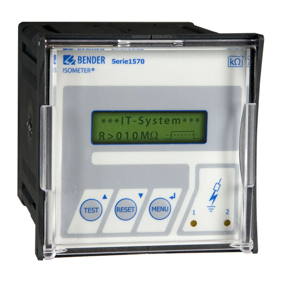
6. Operation and setting 6.1 Operating elements and displays IR1575PG1 1 Two-line display for standard and menu mode 2 TEST button: to activate the self test/ Up key: parameter change, moving up in the menu 3 RESET button: to delete insulation fault alarms/ Down key: parameter change, moving down in the menu 4 MENU key: activating the menu system/ Enter key: confirmation parameter change... -
Page 26: Display In The Standard Mode
Operation and setting 6.1.1 Display in the standard mode 1 Indication of the insulation resistance in kΩ 2 Additional information about the insulation resis- tance: „+“ = insulation fault at L+ „–“ = insulation fault at L– „s“ = new measurement is running = Polarity of the measuring pulse (AMP) 4 Messages: - Insulation fault... -
Page 27: Display In The Eds Mode
Operation and setting 6.1.3 Display in the EDS mode 1 Indication of an insulation fault 2 EDS operating modes: - EDS:on------- - EDS:on-auto-- - EDS:on-1cycle-- = Polarity of the test current 6.1.4 Function keys Two functions are assigned to each function key. In addition to the encircled basic func- tions, all keys allow navigation within the menu. -
Page 28: Menu Structure
Operation and setting Down key: Moving down in the menu, reducing a parameter. ENTER key Selecting a menu item or sub menu item, confirming or storing a parame- ter change and going back to the associated sub menu item or going to the next input area. - Page 29 Operation and setting Changing the parameters When password protection is activated, indicated by the symbol "padlock closed", the first thing to enter is the correct password before the parameters can be changed using the UP/DOWN keys. Entering the correct password once allows all parameters to be changed as long as you do not leave the menu.
-
Page 30: Diagram Menu Structure
Operation and setting 6.2.1 Diagram menu structure 6.3 ISO SETUP menu: ISOMETER® default settings The alarm functions Alarm1 and Alarm2 (prewarning and main alarm), the operating principle of the alarm relays K1 and K2 (N.O = N/O operation, N.C = N/C operation), and fault memory behaviour can be set in this menu. -
Page 31: Operating Principle Of The Alarm Relays
Operation and setting 6.3.2 Operating principle of the alarm relays By default K1/K2 is set to N.O Test, that means N/O operation. The supplement "Test" points out that the setting of the alarm relays changes during a manual self test. If, for any reason, the alarm relays are to be prevented from switching during a manual self test, select N.C or N.O. -
Page 32: Diagram Iso Setup
Operation and setting 6.3.3 Diagram ISO SETUP During the 24 h self test, the relays are not switched over. IR1575PG1_D00357_01_M_XXEN/12.2019... -
Page 33: Memory Setting (On/Off)
Operation and setting On the occurrence of a system fault, the Alarm LED 2 lights and relay K2 will be automatically activated as a system fault relay. 6.3.4 Memory setting (on/off) Memory: on = Fault memory os activated. Reset the device using the RESET button after clearing the fault. -
Page 34: Maxpuls: 10/25 Ma
Operation and setting 6.4.2 maxPuls: 10/25 mA The maximum test current can be set here. 10 mA and 25 mA for EDS460 systems, preferably 25 mA. 10 mA are recommended to be set when sensitive electrical equipment such as control relays are supplied by the system (factory setting 25mA). -
Page 35: Password Menu
Operation and setting 6.5 PASSWORD menu 6.5.1 Password activation and setting A "password" query can be activated in this menu to protect the ISOMETER® against un- authorized settings and modifications. Use the arrow keys to select the desired password (menu item 2. Password: xxx) and confirm with ENTER. -
Page 36: Diagram Password
Operation and setting 6.5.2 Diagram PASSWORD 6.6 LANGUAGE menu 6.6.1 Language setting This menu item offers a selection of two languages for the indication of fault messages. Choose between English and German language. The device menu is indicated in English language and cannot be changed by the lan- guage setting. -
Page 37: Diagram Language
Operation and setting 6.6.2 Diagram Language 6.7 SERVICE menu This menu item is intended for Bender service staff and is secured by a password against erroneous settings. It is intended to provide fast fault clearance by qualified experts. IR1575PG1_D00357_01_M_XXEN/12.2019... -
Page 38: Info Menu
Operation and setting 6.8 INFO menu This menu allows to query the type of the device addressed. In addition, the display in- dicates the software version applied. 6.8.1 Diagram INFO IR1575PG1_D00357_01_M_XXEN/12.2019... -
Page 39: Operation With Eds Device Eds460-D
7. Operation with EDS device EDS460-D-... The illustration below shows an IR1575PG1 in combination with EDS460-D-... without bus capability and the associated measuring current transformers for insulation fault location. In many cases, the device can be operated using the default settings. -
Page 40: Technical Data Ir1575Pg1
8. Technical data IR1575PG1 8.1 Data in tabular form Insulation coordination acc. to IEC 60664-1 Rated voltage ..........................AC 500 V Rated impulse voltage/pollution degree ..................4 kV/3 Voltage ranges IR1575PG1...: Nominal system voltage U ..................AC/3 AC 20…480 V Nominal frequency f ...................... - Page 41 Technical data IR1575PG1 Measuring circuit for insulation measurement Measuring voltage U ........................≤ 20 V Measuring current I (bei R = 0 W) ..................≤ 170 μA Internal DC resistance R ......................≥ 119 kΩ Internal impedance Z , at 50 Hz....................≥ 119 kΩ Permissible extraneous DC voltage U ..................≤...
- Page 42 Technical data IR1575PG1 Ambient temperature (during operation)..............-10 °C…+55 °C Storage temperature range.................... -40 °C…+70 °C Climatic class acc. to IEC 60721-3-3.....................3K5 Operating mode......................continuous operation Position ....................depending on the display position Connection........................plug-in terminals Wire cross section of connecting cable, rigid/flexible......0.2…4 mm /0.2…2.5 mm Connection, flexible with ferrules, without/with plastic collar........
-
Page 43: Standards And Approvals
Technical data IR1575PG1 8.2 Standards and approvals The ISOMETER® was designed in consideration of the following standards: EN 60664-1 EN 61326-2-4 EN 61557-1 EN 61557-8 Subject to change! The specified standards take into account the edition valid until 12.2019 unless otherwise indicated. -
Page 44: Characteristic Curves
Technical data IR1575PG1 8.3 Characteristic curves ISOMETER® reponse times in relation to system leakage capacitances: = 1…60 μF, U = 0…480 V/50 Hz IR1575PG1_D00357_01_M_XXEN/12.2019... - Page 45 Technical data IR1575PG1 Max. AC voltage between the IT system and earth in the frequency range < 50 Hz: 1000 [Hz] Response values for the insulation fault location system EDS460 are available in the de- vice documentation of EDS460 (EDS460-490_D00085...). IR1575PG1_D00357_01_M_XXEN/12.2019...
-
Page 46: Dimension Diagram Enclosure Ir1575Pg1
Technical data IR1575PG1 8.4 Dimension diagram enclosure IR1575PG1 All dimensions in mm suitable for panel mounting, the illustration below shows the necessary cutout: All dimensions in mm IR1575PG1_D00357_01_M_XXEN/12.2019... -
Page 47: Ordering Details
Technical data IR1575PG1 8.5 Ordering details 8.5.1 Standard version Nominal voltage Supply voltage Type Art. No. AC 88…264 V 3/(N) AC 20…480 V IR1575PG1-435 AC 340…460 V B91064002 AC 20…480 V DC 77…286 V AC 88…264 V 3/(N) AC 20…480 V IR1575PG1W-435 AC 340…460 V B91064002W... -
Page 48: Index
INDEX Intended use 11 Alarm LED 1 25 Menu - EDS SETUP 33 - INFO 38 Changing from menu mode to standard mode 29 - ISO SETUP 30 Characteristic curves 44 - LANGUAGE 36 Characteristics 13 - PASSWORD 35 Commissioning 17 - SERVICE 37 Connection 22 Menu structure 30... - Page 52 Bender GmbH & Co. KG P.O. Box 1161 • 35301 Grünberg • Germany Londorfer Str. 65 • 35305 Grünberg • Germany Tel.: +49 6401 807-0 • Fax: +49 6401 807-259 E-mail: info@bender.de • www.bender.de © Bender GmbH & Co. KG All rights reserved.
Need help?
Do you have a question about the ISOMETER IR1575PG1 and is the answer not in the manual?
Questions and answers