Bender ISOMETER isoMED427 Series Manual
Insulation monitoring device for medical applications
Hide thumbs
Also See for ISOMETER isoMED427 Series:

Related Manuals for Bender ISOMETER isoMED427 Series


Summary of Contents for Bender ISOMETER isoMED427 Series
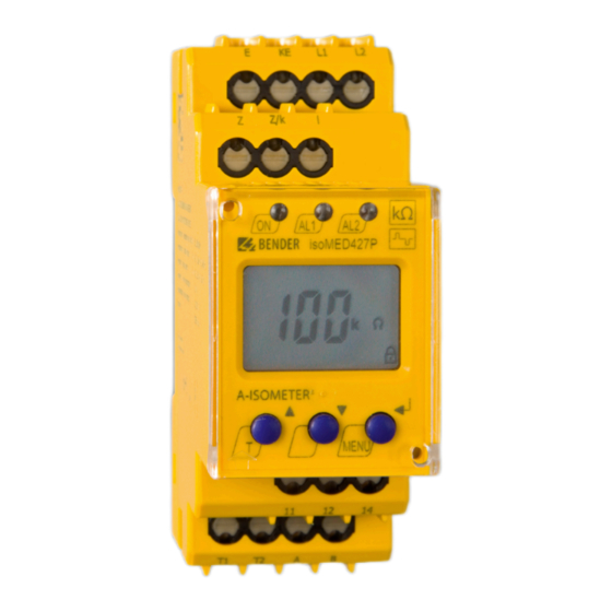
- Page 1 Manual EN ISOMETER® isoMED427x-(PT) Insulation monitoring device for medical applications isoMED427x-(PT)_D00440_02_M_XXEN/04.2024...
- Page 2 isoMED427x-(PT)_D00440_02_M_XXEN/04.2024...
-
Page 3: Table Of Contents
Signs and symbols............................5 Service and Support............................5 Training courses and seminars........................6 Delivery conditions............................6 Inspection, transport and storage......................6 Warranty and liability.............................6 Disposal of Bender devices..........................7 1.10 Safety..................................7 Device-specific safety information..................8 Intended use..............................8 Functional description..................... 9 Alarm and operating messages for each BMS channel..............10 Mounting and connection..................... - Page 4 Table of contents Technical data isoMED427(P)-(PT)................20 Factory settings isoMED427x-(PT)......................24 Ordering data..............................25 Recommended device combinations....................25 Standards and certifications........................25 Change log...............................26 isoMED427x-(PT)_D00440_02_M_XXEN/04.2024...
-
Page 5: General Information
Protect from dust Temperature range Recycling RoHS directives Service and Support Information and contact details about customer service, repair service or field service for Bender devices are available on the following website: Fast assistance | Bender GmbH & Co. KG. isoMED427x-(PT)_D00440_02_M_XXEN/04.2024... -
Page 6: Training Courses And Seminars
Regular face-to-face or online seminars for customers and other interested parties: www.bender.de > know-how > seminars. Delivery conditions The conditions of sale and delivery set out by Bender GmbH & Co. KG apply. These can be obtained in printed or electronic format. The following applies to software products: "Software clause in respect of the licensing of standard software as part of deliveries,... -
Page 7: Disposal Of Bender Devices
ISOMETER® isoMED427x-(PT) Disposal of Bender devices Abide by the national regulations and laws governing the disposal of this device. For more information on the disposal of Bender devices, refer to www.bender.de > service & support. 1.10 Safety If the device is used outside the Federal Republic of Germany, the applicable local standards and regulations must be complied with. -
Page 8: Device-Specific Safety Information
Device-specific safety information Device-specific safety information CAUTION Risk of property damage due to unprofessional installation! If more than one insulation monitoring device is connected to a conductively connected system, the system may be damaged. If several devices are connected, the device does not work and does not signal insulation faults. -
Page 9: Functional Description
Measuring current transformer interruption E.04 Measuring current transformer short circuit E.05…E.xx Internal device error, contact Bender service. Password protection If the password protection has been enabled, settings can only be made after entering the correct password. Factory settings FAC After restoring the factory settings, all settings previously changed are reset to the state upon delivery. -
Page 10: Alarm And Operating Messages For Each Bms Channel
Functional description Monitoring of the IT system transformer For temperature monitoring, the isoMED427P-PT device evaluates the resistance value of the temperature sensor. If the switching threshold of 4 k (isoMED427x) or the set temperature value (isoMED427P-PT) is reached, an overtemperature alarm is triggered. The display shows " > °C". ADVICE Temperature values are only displayed on the isoMED427P-PT. -
Page 11: Mounting And Connection
ISOMETER® isoMED427x-(PT) Mounting and connection DANGER Risk of fatal injury due to electric shock! Touching live parts of the system carries the risk of an electric shock. • Before installing and connecting the device, make sure that the installation has been de-energised. •... -
Page 12: Wiring Diagram
Mounting and connection Wiring diagram DANGER Risk of electrocution due to electric shock! If terminals L1, L2 of the device are connected to an energised IT system, terminals E and KE must not be disconnected from the protective conductor (PE). Connect the device according to the wiring diagram. -
Page 13: Operating Elements
ISOMETER® isoMED427x-(PT) Operating elements Device front Element Function Power on LED Alarm LED 1 is lit: Below response value R Alarm LED 2 is lit: Response value % I or/and °C exceeded "T": Start a self test (2 s) : Menu item up / increase value : Menu item down / decrease value Start menu mode (2 s) Enter button:... -
Page 14: Display In Standard Mode
Operating elements Display in standard mode If there is no alarm pending, the ON LED is lit and the currently measured values are shown on the display. The arrow-up/arrow-down buttons can be used to switch between the insulation resistance value, the percentage load current and the transformer temperature. -
Page 15: Parameter Settings
ISOMETER® isoMED427x-(PT) Parameter settings An example is given below on how to change the alarm response value R (< R). Proceed as follows: Press and hold the MENU/Enter button for 2 s. The flashing short symbol < R appears on the display. Confirm with Enter. -
Page 16: Menu Overview
Parameter settings Menu overview > < 1.5 s < R [k ] > > 1.5 s 1.5 s . . . > I [mA] > °C [°C] < t > 5 Min. < > 1.5 s < R [k ] >... -
Page 17: Setting The Response Value R An (
ISOMETER® isoMED427x-(PT) Setting the response value R (<R) Use this setting to define the insulation value below which an alarm is signalled. > > > > Setting the response value for load current monitoring > > > > > Setting the response value overtemperature ( >°C) (isoMED427P-PT) C °... -
Page 18: Deactivating The Ct Monitoring Function
Parameter settings a) Enabling the password protection > b) Changing the password > c) Disabling the password protection > Deactivating the CT monitoring function > isoMED427x-(PT)_D00440_02_M_XXEN/04.2024... -
Page 19: Resetting The Device To Factory Settings
ISOMETER® isoMED427x-(PT) 6.10 Resetting the device to factory settings > 6.11 Querying device information This function is used to query the software (1.xx) version. After activating this function, the data will be displayed as scrolling text. After completing the routine, individual data sections can be selected using the arrow-up/arrow-down buttons. -
Page 20: Technical Data Isomed427(P)-(Pt)
Technical data isoMED427(P)-(PT) Technical data isoMED427(P)-(PT) Insulation coordination acc. to IEC 60664-1/-3 Definitions Measuring circuit (IC1) L1, L2 Control circuit (IC2) E, KE, Z, Z/k, l, T1, T2, A, B Output circuit (IC3) 11, 12, 14 Rated voltage 250 V Overvoltage category Operating altitude <... - Page 21 ISOMETER® isoMED427x-(PT) Insulation monitoring acc. to IEC 61557-8: 2007-01 Response value R 50…500 k Relative uncertainty ±10 % Hysteresis 25 % Response time t at R = 0.5 × R and C = 0.5 F ≤ 5 s Response time for connection monitoring PE ≤...
- Page 22 Technical data isoMED427(P)-(PT) Temperature monitoring isoMED427x Sensor PTC resistors acc. to DIN 44081 (max. 6 in series) Response value Release value 1.6 k Relative uncertainty ± 10 % Response time, overtemperature < 2 s isoMED427P-PT Sensor PT100 (no series or parallel connections) Response value 50…150 °C Hysteresis...
- Page 23 ISOMETER® isoMED427x-(PT) Switching elements Number 1 changeover contact Operating principle N/C operation / N/O operation Electrical endurance under rated operating conditions 10,000 cycles Contact data acc. to IEC 60947-5-1 Utilisation category AC-13 / AC-14 / DC-12 / DC-12 / DC-12 Rated operational voltage 230 V / 230 V / 24 V / 110 V / 220 V Rated operational current...
-
Page 24: Factory Settings Isomed427X-(Pt)
Technical data isoMED427(P)-(PT) Connection type Screw-type terminals Nominal current ≤ 10 A Tightening torque 0.5…0.6 Nm (5…7 lb-in) Cross section AWG 24-12 Stripping length 8 mm Connection properties: rigid /flexible 0.25…2.5 mm Flexible with ferrules with/without plastic sleeve 0.25…2.5 mm Multi-conductor rigid/flexible 0.2…1.5 mm Multi-conductor flexible with ferrule without plastic... -
Page 25: Ordering Data
ISOMETER® isoMED427x-(PT) BMS address: Automatic insulation fault location: off, deactivated Password: 0, disabled CT monitoring: on, activated Termination: off, deactivated (120 ) Ordering data ISOMETER® Model Supply voltage U Article number Push-wire Screw-type terminals terminals isoMED427-2 AC 70…264 V; 47…63 Hz B72075306 B92075306 isoMED427P-2... -
Page 26: Change Log
Technical data isoMED427(P)-(PT) The Lloyd's Register certification is only valid for the spring-type terminal version of the isoMED427P-2 (B72075301). EU Declaration of Conformity The EU Declaration of Conformity is available at the following Internet address: https://www.bender.de/fileadmin/content/Products/CE/CEKO_isoMED427P-2.pdf Change log Date Document Valid from... - Page 27 ISOMETER® isoMED427x-(PT) isoMED427x-(PT)_D00440_02_M_XXEN/04.2024...
- Page 28 Alle Rechte vorbehalten. 35305 Grünberg Nachdruck und Vervielfältigung nur mit Germany Genehmigung des Herausgebers. © Bender GmbH & Co. KG, Germany Subject to change! The specified Tel.: +49 6401 807-0 All rights reserved. standards take into account the edition info@bender.de Reprinting and duplicating only with valid until 04.2024 unless otherwise...
Need help?
Do you have a question about the ISOMETER isoMED427 Series and is the answer not in the manual?
Questions and answers