Table of Contents

Related Manuals for Bender ISOMETER isoPV with AGH-PV


Summary of Contents for Bender ISOMETER isoPV with AGH-PV
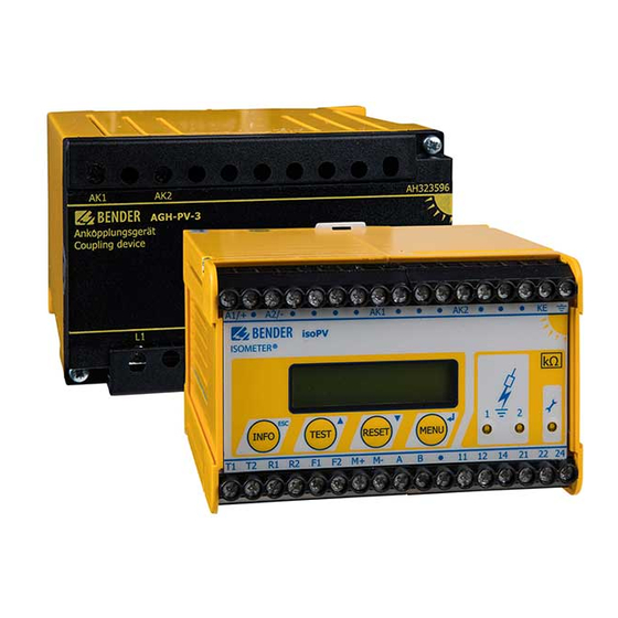
- Page 1 Manual ISOMETER® isoPV coupling device AGH-PV Insulation monitoring device for unearthed IT AC, AC/DC and DC systems for photovoltaic systems up to AC 793 V/DC 1100 V Software version: D351 V2.0 isoPV_D00024_02_M_XXEN/07.2018...
- Page 2 Bender GmbH & Co. KG Londorfer Str. 65 • 35305 Grünberg • Germany P.O. Box 1161 • 35301 Grünberg • Germany Tel.: +49 6401 807-0 • Fax: +49 6401 807-259 E-mail: info@bender.de • www.bender.de © Bender GmbH & Co. KG All rights reserved.
-
Page 3: Table Of Contents
Table of Contents 1. Important information ................7 How to use this manual ..................7 Technical support: service and support ............8 1.2.1 First level support ....................8 1.2.2 Repair service ......................8 1.2.3 Field service ....................... 9 Training courses ....................... 9 Delivery conditions .................... - Page 4 Table of Contents 3.4.4 Real-time clock ....................... 19 3.4.5 Coupled IT systems ....................19 3.4.6 Function input F1/F2 for connection or disconnection of IT systems being monitored ................19 3.4.7 ISOnet function (COM SETUP) ................21 4. Commissioning flow chart (threepart) ..........22 5.
- Page 5 Table of Contents 6.5.4 Setting the repetition time for the automatic self test (Autotest: 24h) ......................43 6.5.5 Setting the real-time clock (Clock) ..............44 6.5.6 Setting the date (Date) ..................44 6.5.7 Specifying the start-up time for the automatic self test (Test) ..... 44 6.5.8 Diagram ISO ADVANCED ..................
- Page 6 Table of Contents 9. Technical data isoPV with AGH-PV ............ 59 Data in tabular form isoPV .................. 59 Technical data in tabular form AGH-PV ............62 Standards, approvals and certifications ............63 Characteristic curves .................... 64 Ordering information ................... 68 isoPV_D00024_02_M_XXEN/07.2018...
-
Page 7: Important Information
1. Important information 1.1 How to use this manual This manual is intended for qualified personnel working in electrical engineering and electronics! Pleas read this manual before mounting, connecting and commissioning the device. Always keep this manual within easy reach for future reference. To make it easier for you to understand and revisit certain sections in this manual, we have used symbols to identify important instructions and information. -
Page 8: Technical Support: Service And Support
• Hardware and software update for Bender devices • Delivery of replacement devices in the event of faulty or incorrectly delivered Bender devices • Extended guarantee for Bender devices, which includes an in-house repair service or replacement devices at no extra cost Telephone:... -
Page 9: Field Service
ZVEI (Zentralverband Elektrotechnik- und Elektronikindustrie e. V.) (German Electrical and Electronic Manufacturer's Association) also applies. Sale and delivery conditions can be obtained from Bender in printed or electronic for- mat. 1.5 Inspection, transport and storage Inspect the dispatch and equipment packaging for damage, and compare the contents of the package with the delivery documents. -
Page 10: Warranty And Liability
13 August 2005 must be taken back by the manufacturer and disposed of properly. For more information on the disposal of Bender devices, refer to our homepage at www.bender-de.com -> Service & support. -
Page 11: Safety Instructions
• monitoring the insulation resistance of IT systems Use which deviates from or is beyond the scope of the intended use is considered non- compliant. The Bender companies shall not be liable for any losses or damage arising therefrom. Intended use also implies: •... -
Page 12: Personnel
Safety instructions 2.3.1 Personnel Only appropriately qualified personnel may work on the ISOMETER®. Qualified means familiar with the installation, commissioning and operation of the product and with training appropriate to the work. Personnel must have read and understood the safety section and warning information in this operating manual. -
Page 13: Directions For Installation
Safety instructions 2.4 Directions for installation Only one insulation monitoring device may be used in each interconnected IT system. When insulation or voltage tests are to be carried out, the device shall be isolated from the system for the test period.. The terminals and KE have to be connected by a separate wire to the protective con- ductor (PE). - Page 14 Safety instructions For systems ≤ 30 kVA it is imperative that: the insulation resistance between the inverter input and the earth is at least 500 k . For Ω mains voltages greater than 500 V the formula below applies: 1kΩ •...
-
Page 15: Function
• Memory with real-time clock to store alarm messages with date and time stamp • BMS interface (Bender Measuring Device Interface) for communication with other Bender devices (RS-485 galvanically isolated) • Internal disconnection of the ISOMETER® (via control signal; terminals F1/F2) from the IT system to be monitored (e.g. -
Page 16: Application
Function 3.3 Application ® The ISOMETER type isoPV in combination with the AGH-PV coupling device monitors the insulation resistance of IT systems. It is suitable for universal use in 3(N) AC, AC/DC and DC systems. AC systems may include extensive DC-supplied loads, such as conver- ters or thyristor-controlled DC drives. -
Page 17: Measurement Profiles
The fault memory behaviour can also be set in the "ISO SETUP“ menu, by selecting the submenu Memory: on/off. measurement method (Adaptive Measuring Pulse), a measurement method developed by Bender (European Patent: EP 0 654 673 B1). 3.4.1... -
Page 18: Current Output For External Measuring Instrument
Internal device error 2. Switch the supply voltage off and on 3. Please contact Bender If, for functional reasons, the supply voltage cannot be switched on and off, a reset of the sequence control system can be carried out by pressing the buttons "RESET", "MENU"... -
Page 19: Real-Time Clock
Function 3.4.4 Real-time clock The real-time clock serves as a time base for the memory and self test functions. First, the correct time and date must be set in the "ISO ADVANCED" menu. If time and date are not set, a "C" (clock) is flashing in the standard display. In the event of a supply vol- tage failure, time and date will be stored for at least 30 days. - Page 20 Function ® ISOMETER s would be deactivated. In order to prevent this, a BMS master (BMS addr. 1) monitors the condition of the function input F1/F2 of all slave ® ® ISOMETER s. When all slave ISOMETER s are in the STANDBY mode, the insulation mo- ®...
-
Page 21: Isonet Function (Com Setup)
Function 3.4.7 ISOnet function (COM SETUP) To activate this function, select "ISOnet=ON" in the COM SETUP menu. This function is a type of scanning function. The BMS master with activated ISOnet function controls ® the ISOnet slave devices via the BMS bus. When the master ISOMETER has finished one measuring cycle, the authorisation for insulation monitoring is passed on to the next ®... -
Page 22: Commissioning Flow Chart (Threepart)
4. Commissioning flow chart (threepart) ® Commissioning of the ISOMETER isoPV_D00024_02_M_XXEN/07.2018... - Page 23 Commissioning flow chart (threepart) ® Commissioning of the ISOMETER isoPV_D00024_02_M_XXEN/07.2018...
- Page 24 Commissioning flow chart (threepart) ® Commissioning of the ISOMETER isoPV_D00024_02_M_XXEN/07.2018...
-
Page 25: Installation And Connection
5. Installation and connection Risk of electrocution due to electric shock! Touching live parts of the system carries the risk of: • Electrocution due to an electric shock DANGER • Damage to the electrical installation • Destruction of the device Before installing and connecting the device, make sure that the installation has been de-energised. -
Page 26: Installation Of The Isopv
Installation and connection Check proper connection! Prior to commissioning of the installation, check that the device has been properly connected and check the device functions. Perform a functional test using an earth fault via a suitable resistance. Prevent measurement errors! When the AC system being monitored contains galvanically coupled DC circuits, take into consideration that: an insulation fault can only be detected correctly when the rectifier valves carry a minimum current of >... -
Page 27: Wiring Diagram
Installation and connection 5.2 Wiring diagram The terminals A1/+ and A2/- are to be connected to the supply voltage according to IEC 60364-4-43, that means, the connections are to be protected against short-circuit by means of a protective device (a 6 A fuse is recommended). For UL and CSA applications, the use of 5 A fuses is mandatory. - Page 28 Installation and connection isoPV_D00024_02_M_XXEN/07.2018...
- Page 29 Installation and connection Legend wiring diagram: Supply voltage U (see nameplate) via 6 A fuse; For UL and CSA applications, the use of 5 A fuses is mandatory. 2, 3 Connection to the 3 AC system to be monitored: Connect the terminals L1, L2 to neutral conductor N or terminals L1, L2 to conductor L1, L2.
-
Page 30: Operation And Setting
Operation and setting 6. Operation and setting 6.1 Display and operating elements "INFO" button: to query standard information/"ESC" button: back (menu function), to confirm parameter change "TEST" button: to call up the self test/arrow up button: parameter change, to move up in the menu "RESET"... -
Page 31: Display In Standard Mode
6.1.1 Display in standard mode Indication of the insulation resistance in kW Additional information about the insulation resis- tance: „+“ = Insulation fault at L+ „–“ = Insulation fault at L– „s" = New measurement is being started = Polarity of the measuring pulse, = Valid BMS bus communication, H = New entry in the memory data base C = Flashing, clock is to be set... - Page 32 Page 66 • COM-Setup (isoPV's own bus address) Please have the details above on hand if you have a problem and if you contact Bender for technical questions. Press the "TEST" button to start the self test of the ®...
- Page 33 Operation and setting For menu control, the arrow buttons, Enter button and the "ESC" button are used: Up button: To move up in the menu, to increase the parameter value Down button: To move down in the menu, to decrease the parameter value Enter button: To select a menu item or sub menu item, confirm or store a parameter change and to return to the associated sub menu item or skip to the next...
-
Page 34: Menu Structure And Menu Mode
Operation and setting 6.2 Menu structure and menu mode How to access the menu mode Press the "MENU" button to switch from the standard mode to the menu mode and to the main menu. From here you can branch to the different submenus. 6.2.1 Navigation within the menu Use the Up and Down buttons to select the appropriate menu item. -
Page 35: Diagram Menu Structure
Operation and setting 6.2.4 Diagram menu structure isoPV_D00024_02_M_XXEN/07.2018... -
Page 36: Menu History Info
Operation and setting 6.3 Menu HISTORY INFO 99 events with date and time stamp can be stored in the memory database. The data- base is designed as a ring memory, i.e. the eldest entry is overwritten. Data is written into a non-volatile memory and therefore is protected against voltage failure. To store the events with the actual date and time stamp, you need to set the real-time clock in the ISO ADVANCED menu first. -
Page 37: Diagram History Info
Operation and setting 6.3.1 Diagram HISTORY INFO isoPV_D00024_02_M_XXEN/07.2018... -
Page 38: Menu Iso Setup: Setting Of The Basic Isometer Functions
Operation and setting 6.4 Menu ISO SETUP: Setting of the basic ISOMETER functions This menu is used to set the alarm functions Alarm1 and Alarm2 (prewarning and alarm), the operating principle of the alarm relay K1 and K2 (N.O = N/O operation, N.C = N/C operation), the fault storage behaviour and a selection of two current output ranges. -
Page 39: Operating Principle Of The Alarm Relays
Operation and setting 6.4.2 Operating principle of the alarm relays K1/K2 are factory-set to N.O Test, that means N/O operation. When the supplement "Test" has been selected, the alarm relays switch over during a manual self test. If the operating principle of the alarm relays does not have to be changed during a ma- nual self test for any reason, N.C or N.O. - Page 40 Operation and setting ISO SETUP diagram During the automatic self test, the alarm relays are not switched over. isoPV_D00024_02_M_XXEN/07.2018...
-
Page 41: Memory Setting (On/Off)
Operation and setting When a device error occurs at the ISOMETER, the relay K2 will automatically be activated as a device error relay. 6.4.3 Memory setting (on/off) Memory: on = Fault memory is activated The device must be reset with the Reset button after clearing the fault. -
Page 42: Menu Iso Advanced: Setting Of The Extended Functions
Operation and setting 6.5 Menu ISO ADVANCED: Setting of the extended functions 6.5.1 External coupling device (AGH: PV) Use the isoPV only in combination with the coupling device AGH-PV. The menu setting AGH:PV is pre-defined. The current software version does not allow other settings. 6.5.2 Adaptation of the system leakage capacitance (Cemax: 2000 μF) ®... -
Page 43: Setting The Repetition Time For The Automatic Self Test
Operation and setting 6.5.4 Setting the repetition time for the automatic self test (Autotest: 24h) Setting the parameter e max 150μF 500μF 2000μF Response time Response time Response time (acc. to IEC Profile 61557-8) Description setting = 1kΩ = 1kΩ = 1kΩ... -
Page 44: Setting The Real-Time Clock (Clock)
Operation and setting 6.5.5 Setting the real-time clock (Clock) The time setting is the time base for the memory and the automatic self test. In case of supply voltage failure, the set real-time clock keeps running for approximately 30 days. When the device is switched on after this period, a flashing "C"... -
Page 45: Diagram Iso Advanced
Operation and setting 6.5.8 Diagram ISO ADVANCED isoPV_D00024_02_M_XXEN/07.2018... -
Page 46: Menu Com Setup: Setting The Bms Interface
Operation and setting 6.6 Menu COM SETUP: Setting the BMS interface 6.6.1 Bus address "Addr:" This menu is used to set the BMS bus address for isoPV. Take care that the bus address is not assigned twice. The device is factory set to address 3 and hence operates as a slave. Please note that the capacitance cannot be measured when using the profiles AMP3 or AMP4. -
Page 47: Diagram Com Setup
Operation and setting 6.6.4 Diagram COM SETUP isoPV_D00024_02_M_XXEN/07.2018... -
Page 48: Password Menu
Operation and setting 6.7 PASSWORD menu 6.7.1 Setting and activating the password This menu can be used to activate a "Password" query. This protects the ® ISOMETER against unauthorised settings and modifications. Set the desired password using the UP/DOWN buttons (menu item "2. Password: xxx") and confirm the setting with the ENTER button. -
Page 49: Language Menu
Language diagram 6.9 SERVICE menu This menu item is intended for the Bender service personnel and protected by a pass- word against erroneous settings. It is intended for fast fault clearance by qualified ex- perts in the event of a device error. -
Page 50: Serial Interface
Serial interface 7. Serial interface 7.1 RS-485 interface with BMS protocol The RS-485 interface electrically isolated from the device electronics and the current output serves as a physical transmission medium for the BMS protocol. If several isoPV or other bus-capable devices are interconnected in a network via the BMS bus, the BMS bus must be terminated at both ends with a 120 Ω... -
Page 51: Correct Arrangement
(z.B. J-Y(St)Y 2x0.6), shield connected to earth (PE) on one end. Connection to the terminals A and B. The number of bus nodes is restricted to 32 devices. When more devices are to be con- nected, Bender recommends to use a DI1 repeater. isoPV_D00024_02_M_XXEN/07.2018... -
Page 52: Bms Protocol
Serial interface 7.3 BMS protocol This protocol is an essential part of the Bender measuring device interface (BMS bus protocol). Data transmission generally makes use of ASCII characters. Interface data are: • Baud rate: 9,600 baud • Transmission: 1 start bit, 7 data bits, 1 parity bit, 1 stop bit (1, 7, E, 1) •... -
Page 53: Bms Slave
Serial interface 7.3.2 BMS slave All isoPV devices are factory-set to slave mode (address 3). In a BMS network, one address must be selected from the address range 2…30 for each slave. There may be no gaps of more than five subsequent addresses, so that all slaves can be scanned by the master. -
Page 54: Commissioning Of An Rs-485 Network With Bms Protocol
Serial interface 7.3.3 Commissioning of an RS-485 network with BMS protocol • Connect the terminals A and B of all bus devices in one line • Switch the terminating resistors on at the beginning and end of the RS-485 net- work or if there are devices which do not include a terminating switch at the end of the bus, place a 120 Ω... - Page 55 Serial interface BMS bus address ranges (internal bus) Addresses* Device Note There is no device with address 0 !. Information sent to address 0 applies to all devices connected to the interfaces (broadcast) IRDH275B/ 1…30 375B/575; Insulation monitoring devices isoPV 1…30 FTC4…...
-
Page 56: Coupled Pv Generators (Application Example)
Coupled PV generators (application example) 8. Coupled PV generators (application example) isoPV_D00024_02_M_XXEN/07.2018... - Page 57 isoPV_D00024_02_M_XXEN/07.2018...
- Page 58 Coupled PV generators (application example) isoPV_D00024_02_M_XXEN/07.2018...
-
Page 59: Technical Data Isopv With Agh-Pv
9. Technical data isoPV with AGH-PV 9.1 Data in tabular form isoPV The values marked with** are absolute values. ()* = factory setting Insulation coordination acc. to IEC 60664-1 Definitions: Supply circuit (IC2) ..............................A1, A2 Output circuit (IC3)............................... 11, 14, 24 Control circuit (IC4) ......................Up, KE, T/R, A, B, AK1, GND, AK2 Rated voltage ..................................240 V Overvoltage category................................. - Page 60 Technical data isoPV with AGH-PV Supply voltage U (also see nameplate)....................... DC 19.2…72 V** Power consumption ................................ ≤ 6 VA For UL-application Nominal system voltage U ............................. via AGH-PV isoPV-335: Supply voltage U (also see nameplate)......................AC 88…250 V Frequency range U ...............................
- Page 61 Technical data isoPV with AGH-PV Accuracy current output, related to the value indicated (1 kΩ … 100 kΩ) .................... ±15 %, ±1 k W Serial interface Interface/protocol..............................RS-485/BMS Connection ................................terminals A/B ≤ Cable length................................1,200 m Shielded cable (shield to PE on one end) ..............2-core, ≥ 0.6 mm , z.
-
Page 62: Technical Data In Tabular Form Agh-Pv
Technical data isoPV with AGH-PV Other Operating mode ............................continuous operation Mounting ................................display oriented Distance to adjacent devices ............................≥ 30 mm Degree of protection, internal components (DIN EN 60529)....................IP30 Degree of protection, terminals (DIN EN 60529)........................IP20 Type of enclosure...........................X112, free from halogen DIN rail mounting.......................... -
Page 63: Standards, Approvals And Certifications
Technical data isoPV with AGH-PV Tightening torque................................0.5 Nm Conductor sizes (AWG)..............................24…12 ≤ Cable length between isoPV and AGH-PV ........................0.5 m Other Operating mode ............................continuous operation Mounting ........................ cooling slots must be ventilated vertically! Distance to adjacent devices ............................≥ 30 mm Degree of protection, internal components (DIN EN 60529) ....................IP30 Degree of protection, terminals (DIN EN 60529)........................IP20 Type of enclosure.......................... -
Page 64: Characteristic Curves
Technical data isoPV with AGH-PV 9.4 Characteristic curves Current output 0…20 mA [k:] 1000,00 Rsk=28kOhm Rsk=120kOhm 100,00 10,00 1,00 10,0 15,0 20,0 25,0 I[mA] = Insulation fault in kW = Centre scale in kW I = Current output in mA isoPV_D00024_02_M_XXEN/07.2018... - Page 65 Technical data isoPV with AGH-PV Current output 4…20 mA [k:] 1000,00 Rsk=28kOhm Rsk=120kOhm 100,00 10,00 1,00 10,0 15,0 20,0 25,0 I[mA] = Insulation fault in kW = Centre scale in kW I = Current output in mA isoPV_D00024_02_M_XXEN/07.2018...
- Page 66 Technical data isoPV with AGH-PV Status number isoPV_D00024_02_M_XXEN/07.2018...
- Page 67 Technical data isoPV with AGH-PV Dimension diagram enclosure isoPV All dimensions in mm • DIN rail mounting according to DIN EN 60715/IEC 60715 • Screw fixing by means of a plug-in trapezoidal support Order-No. B990056 Dimension diagram enclosure AGH-PV All dimensions in mm Illustration with terminal covers isoPV_D00024_02_M_XXEN/07.2018...
-
Page 68: Ordering Information
Technical data isoPV with AGH-PV 9.5 Ordering information Nominal voltage U Supply voltage U Type Art.No. isoPV-327 3(N)AC 0…793 V AC 19.2…55 V B91065132W + AGH-PV DC 0…1100 V 42…460 Hz consisting of: DC 19.2…72 V isoPV-327 – – B91065130W AGH-PV –... - Page 69 Assigning the bus address for iso-PV 46 Flashing point 53 Automatic self test, setting 43 Function input F1/F2 19 Bender Measuring Device Interface (BMS) 52 History memory 36 BMS addresses 55 How to use this manual 7 BMS master 52...
- Page 70 INDEX Menü - ISO ADVANCED 42 Technical data 59 - structure 35 terminated RS-485 network 50 Minimum current rectifier 26 Terminating resistor 50 Test button 30 Topology RS-485 network 50 Operation Training courses 9 - Commissioning 26 Ordering information 68 wiring 51 Wiring diagram ISOMETER®...
- Page 72 Bender GmbH & Co. KG Londorfer Str. 65 • 35305 Grünberg • Germany P.O. Box 1161 • 35301 Grünberg • Germany Tel.: +49 6401 807-0 • Fax: +49 6401 807-259 E-mail: info@bender.de • www.bender.de © Bender GmbH & Co. KG All rights reserved.
Need help?
Do you have a question about the ISOMETER isoPV with AGH-PV and is the answer not in the manual?
Questions and answers