Table of Contents
Advertisement
Available languages
Available languages
Quick Links
Advertisement
Chapters
Table of Contents

Related Manuals for Bender ISOMETER IRDH275


Summary of Contents for Bender ISOMETER IRDH275
- Page 1 Handbuch ISOMETER® IRDH275 IRDH275B Isolationsüberwachungsgerät für IT-Wechselspannungssysteme mit galvanisch verbundenen Gleich- und Umrichtern und für IT-Gleichspannungssysteme Software-Version IRDH275: D0160 V1.8 IRDH275_D00122_03_M_XXDE/05.2017...
- Page 2 Bender GmbH & Co. KG Londorfer Str. 65 • 35305 Grünberg • Germany Postfach 1161 • 35301 Grünberg • Germany Tel.: +49 6401 807-0 Fax: +49 6401 807-259 E-Mail: info@bender.de Web: http://www.bender.de © Bender GmbH & Co. KG Alle Rechte vorbehalten.
-
Page 3: Table Of Contents
Inhaltsverzeichnis 1. Wichtig zu wissen ..................... 7 Hinweise zur Benutzung des Handbuchs ..........7 Technische Unterstützung: Service und Support ......... 8 1.2.1 First-Level-Support ..................8 1.2.2 Repair-Service ....................8 1.2.3 Field-Service ....................... 9 Schulungen ..................... 10 Lieferbedingungen ..................10 Kontrolle, Transport und Lagerung ............10 Gewährleistung und Haftung .............. - Page 4 Inhaltsverzeichnis 4. Anschluss ......................29 Zum Anschlussschaltbild ................29 Anschlussschaltbilder mit Ankoppelgeräten ........32 4.2.1 Anschluss mit AGH150W-4 ................ 32 4.2.2 Anschluss mit AGH520S ................33 4.2.3 Anschluss mit AGH204S-4 ................34 5. Inbetriebnahme-Schema (dreiteilig) ............37 6. Bedienung und Einstellung ................. 41 Bedienelemente und Anzeigen IRDH275(B) ........
- Page 5 Inhaltsverzeichnis 6.5.8 Diagramm ISO ADVANCED ................ 57 Menü COM SETUP: Einstellen der BMS-Schnittstelle ....... 58 6.6.1 Busadresse „Addr:“ (IRDH275B) ............... 58 6.6.2 ISOnet Funktion (IRDH275B) ..............58 6.6.3 ISO-Monitor (IRDH275B) ................59 6.6.4 Diagramm COM SETUP (IRDH275B) ............60 Menü PASSWORD ..................61 6.7.1 Passwort einstellen und aktivieren ............
- Page 6 Inhaltsverzeichnis 9. Technische Daten IRDH275(B) ..............75 Tabellarische Daten ..................75 Normen, Zulassungen und Zertifizierungen ........79 Kennlinien ......................80 Bestellangaben ....................87 9.4.1 ISOMETER® ....................... 87 9.4.2 Ankoppelgeräte ..................... 88 9.4.3 Messinstrumente ................... 88 INDEX ........................89 IRDH275_D00122_03_M_XXDE/05.2017...
-
Page 7: Wichtig Zu Wissen
1. Wichtig zu wissen 1.1 Hinweise zur Benutzung des Handbuchs Dieses Handbuch richtet sich an Fachpersonal der Elektrotechnik und Elektronik! Bewahren Sie dieses Handbuch zum Nachschlagen griffbereit auf. Um Ihnen das Verständnis und das Wiederfinden bestimmter Textstellen und Hinweise im Handbuch zu erleichtern, haben wir wichtige Hinweise und Infor- mationen mit Symbolen gekennzeichnet. -
Page 8: Technische Unterstützung: Service Und Support
Wichtig zu wissen Dieses Handbuch wurde mit größtmöglicher Sorgfalt erstellt. Dennoch sind Fehler und Irrtümer nicht vollständig auszuschließen. Bender übernimmt kei- nerlei Haftung für Personen- oder Sachschäden, die sich aus Fehlern oder Irr- tümern in diesem Handbuch herleiten. 1.2 Technische Unterstützung: Service und Support Für die Inbetriebnahme und Störungsbehebung bietet Bender an:... -
Page 9: Field-Service
Wichtig zu wissen Geräte für den Reparaturservice senden Sie bitte an folgende Adresse: Bender GmbH, Repair-Service, Londorfer Str. 65, 35305 Grünberg 1.2.3 Field-Service Vor-Ort-Service für alle Bender-Produkte • Inbetriebnahme, Parametrierung, Wartung, Störungsbeseitigung für Bender-Produkte • Analyse der Gebäudeinstallation (Netzqualitäts-Check, EMV-Check, Thermografie) •... -
Page 10: Schulungen
Wichtig zu wissen 1.3 Schulungen Bender bietet Ihnen gerne eine Einweisung in die Bedienung des Geräts an. Aktuelle Termine für Schulungen und Praxisseminare finden Sie im Internet unter www.bender-de.com -> Fachwissen -> Seminare. 1.4 Lieferbedingungen Es gelten die Liefer- und Zahlungsbedingungen der Firma Bender. -
Page 11: Gewährleistung Und Haftung
Wichtig zu wissen 1.6 Gewährleistung und Haftung Gewährleistung- und Haftungsansprüche bei Personen- und Sachschäden sind ausgeschlossen, wenn sie auf eine oder mehrere der folgenden Ursachen zurückzuführen sind: • Nicht bestimmungsgemäße Verwendung des Geräts. • Unsachgemäßes Montieren, Inbetriebnehmen, Bedienen und Warten des Geräts. -
Page 12: Entsorgung
Altgeräte anderer Nutzer als privater Haushalte, die als Neugeräte nach dem 13. August 2005 in Verkehr gebracht wurden, werden vom Her- steller zurückgenommen und einer fachgerechten Entsorgung zuge- führt. Weitere Hinweise zur Entsorgung von Bender-Geräten finden Sie auf unserer Homepage unter www.bender-de.com -> Service & Support. IRDH275_D00122_03_M_XXDE/05.2017... -
Page 13: Sicherheitshinweise
2. Sicherheitshinweise 2.1 Sicherheitshinweise allgemein Bestandteil der Gerätedokumentation sind neben diesem Handbuch die „Sicherheitshinweise für Bender-Produkte“. 2.2 Arbeiten an elektrischen Anlagen Alle zum Einbau, zur Inbetriebnahme und zum laufenden Betrieb eines Gerätes oder Systems erforderlichen Arbeiten sind durch geeignetes Fachpersonal auszuführen. -
Page 14: Sicherheitshinweise Gerätespezifisch
Sicherheitshinweise 2.3 Sicherheitshinweise gerätespezifisch Personen ohne die erforderliche Sachkunde, insbesondere Kinder, dürfen keinen Zugang und Zugriff zum ISOMETER® haben. WARNUNG Auf richtige Nennanschluss- und Versorgungsspannung achten! Vor Isolations- und Spannungsprüfungen müssen die ISOMETER® für die Dauer der Prüfung vom IT-System getrennt sein. - Page 15 Sicherheitshinweise Für den Einsatz von ISOMETER®n in IT-Systemen gilt generell, dass nur ein aktives ISOMETER® in einem galvanisch miteinander verbundenen System angeschlossen sein darf. Werden IT-Systeme über Koppelschalter zusammengeschaltet, muss über eine Steuerung sichergestellt werden, dass nicht benötigte ISOMETER® vom IT-System getrennt und inaktiv geschaltet werden.
-
Page 16: Bestimmungsgemäße Verwendung
Sicherheitshinweise 2.4 Bestimmungsgemäße Verwendung Das ISOMETER® ist bestimmt: • zur Überwachung des Isolationswiderstandes von IT-Systemen Zur bestimmungsgemäßen Verwendung gehört auch • das Beachten aller Hinweise aus der Bedienungsanleitung und • die Einhaltung eventueller Prüfintervalle. Durch individuelle Parametrierung ist in jedem Falle die Anpassung an die An- lagen- und Einsatzbedingungen vor Ort vorzunehmen, um die Forderungen der Normen zu erfüllen. -
Page 17: Installationshinweis
Sicherheitshinweise 2.5 Installationshinweis Gefahr Sachschaden durch unsachgemäße Installation! Die Anlage kann Schaden nehmen, wenn Sie in einem leitend verbundenen System mehr als ein Isolationsüberwachungs- gerät anschließen. Sind mehrere Geräte angeschlossen, VORSICHT funktioniert Gerät nicht meldet keine Isolationsfehler. Schließen Sie in jedem leitend verbundenen System nur ein Isolationsüberwachungsgerät an. - Page 18 Sicherheitshinweise Messfehler verhindern! Wenn ein überwachtes AC-System galvanisch gekoppelte Gleichstromkreise enthält, gilt: Ein Isolationsfehler kann nur dann wertrichtig erfasst werden, wenn über die Gleichrichterventile ein Mindeststrom von 5…10 mA fließt. IRDH275_D00122_03_M_XXDE/05.2017...
-
Page 19: Funktion
Historienspeicher mit Echtzeituhr zur Speicherung von Alarmmeldun- gen mit Datum und Uhrzeit • BMS-Schnittstelle (Bender-Messgeräte-Schnittstelle) zum Datenaus- tausch mit anderen Bender-Komponenten (RS485 galvanisch getrennt) • Interne Trennung des ISOMETER®s (durch Steuersignal; Klemmen F1/ F2) vom zu überwachenden IT-System (z. B. bei Kopplung mehrerer ISOMETER®) -
Page 20: Produktbeschreibung
Funktion 3.3 Produktbeschreibung Das ISOMETER® Typ IRDH275 überwacht den Isolationswiderstand von IT-Sys- temen. Es ist universell in 3(N) AC-, AC/DC- und DC-Systemen einsetzbar. In AC-Systemen können auch umfangreiche gleichstromgespeiste Anlagenteile vorhanden sein (z.B. Stromrichter, Umrichter, thyristorgeregelte Gleichstrom- antriebe). Die Anpassung an die vorhandene Netzableitkapazität erfolgt auto- matisch. - Page 21 Die Anschlüsse für eine externe kΩ-Anzeige, gespeist durch den Stromaus- gang 0…400 μA oder 0(4)…20 mA (IRDH275B) an M+/M-, sind galvanisch ge- trennt ausgeführt. -Messverfahren (Adaptiver-Mess-Puls), ein von Bender entwi- ckeltes und patentiertes Messverfahren (Europäisches Patent: EP 0 654 673 B1). Selbsttest Ein Selbsttest kann manuell mit der TEST-Taste oder automatisch ausgeführt...
- Page 22 Funktion Wird ein Geräte- oder Anschlussfehler festgestellt, erscheint auf dem LC-Dis- play die Meldung „!Error!“, die Gerätefehler-LED leuchtet, Relais K2 (21-22-24) schaltet und die entsprechende Fehlermeldung (siehe Tabelle) wird angezeigt. In einem solchen Gerätefehlerfall wird periodisch nach ca. 1 Minute ein erneuter Selbsttest gestartet. Wird keine Fehlfunktion mehr fest- gestellt, wird die Fehlermeldung automatisch gelöscht, die Gerätefehler-LED erlischt.
- Page 23 Versorgungsspannung aus- und Gerätefehler x Interner Gerätefehler einschalten Mit Bender in Verbindung setzen Falls das Aus- und Einschalten der Versorgungsspannung aus betriebstechnischen Gründen nicht möglich ist, kann durch gleichzeitige Betätigung der Tasten „INFO“, „RESET“ und „MENU“ ein Zurücksetzen der Ablaufsteuerung durchgeführt werden.
-
Page 24: Zusatzfunktionen Irdh275B
Funktion 3.5 Zusatzfunktionen IRDH275B Stromausgang für externes Messinstrument Beim IRDH275B ist der Stromausgang mit 0(4)…20 mA dimensioniert. Der Stromausgang ist galvanisch getrennt ausgeführt gegen die Geräte-Elektro- nik und die RS485-Schnittstelle. Mit Hilfe des Menüs ISO SETUP, siehe Seite 50, kann zwischen den Bereichen 0…20 mA und 4…20 mA umgeschaltet wer- den. - Page 25 Funktion Funktionseingang F1/F2 zur Ankopplung und Trennung von über- wachten IT-Systemen Mit dem Funktionseingang F1/F2 kann das ISOMETER® vom IT-System ge- trennt und in einen STANDBY-Modus gesetzt werden. Wird der Eingang F1/F2 gebrückt, werden die Anschlüsse L1/L2 über interne Koppelrelais abgeschal- tet, die Messfunktion angehalten sowie auf dem Display die Meldung „STANDBY“...
- Page 26 Funktion IRDH275_D00122_03_M_XXDE/05.2017...
- Page 27 Funktion ISOnet-Funktion (COM SETUP) Um diese Funktion zu aktivieren, muss „ISOnet=ON“ im Menü COM SETUP ein- gestellt werden. Bei dieser Funktion handelt es sich um eine Art Scanning- Funktion. Der BMS-Master, bei dem die ISOnet-Funktion aktiviert wurde, steu- ert über den BMS-Bus die ISOnet-Slave-Geräte. Hat ein ISOMETER® einen Messzyklus beendet, wird die Berechtigung zur Isolationsmessung von dem ISOnet-Master an den nächsten Slave weitergegeben.
- Page 28 Funktion IRDH275_D00122_03_M_XXDE/05.2017...
-
Page 29: Anschluss
4. Anschluss Alle zum Einbau, zur Inbetriebnahme und zum laufenden Betrieb eines Gerätes oder Systems erforderlichen Arbeiten sind durch geeignetes Fachpersonal auszuführen. Lebensgefahr durch Stromschlag! Bei Berühren von unter Spannung stehenden Anlagenteilen besteht die Gefahr • eines elektrischen Schlages, • von Sachschäden an der elektrischen Anlage, •... - Page 30 Anschluss Mit einer externen TEST-Taste oder einer externen RESET-Taste darf nur ein ISOMETER® angesteuert werden. Eine galvanische Parallelschaltung mehrerer TEST- oder RESET-Eingänge für Sammelprüfungen von ISOMETER®n ist nicht erlaubt. Externe Ankoppelgeräte, die über die Klemme AK angeschlossen werden, können nicht über die internen Koppelrelais abgeschaltet werden. Wird kein Ankoppelgerät benötigt, bleibt die Klemme AK frei.
- Page 31 Anschluss Legende Anschlussplan: Versorgungsspannung U (siehe Typenschild) über Schmelzsicherung 6 A; für UL- und CSA-Applikationen sind 5 A-Vorsicherungen zwingend zu verwenden Anschluss an das zu überwachende 3 AC-System: Klemmen L1, L2 mit Neutral-Leiter N oder Klemmen L1, L2 mit Leiter L1, L2 verbinden Anschluss an das zu überwachende AC-System: Klemmen L1, L2 mit Leiter L1, L2 verbinden Anschluss an das zu überwachende DC-System:...
-
Page 32: Anschlussschaltbilder Mit Ankoppelgeräten
Anschluss 4.2 Anschlussschaltbilder mit Ankoppelgeräten Beachten Sie die Einstellungen im Menü „ISO ADVANCED AGH“! Passen Sie die Einstellungen an das verwendete Ankoppelgerät an. 4.2.1 Anschluss mit AGH150W-4 Dieses Ankoppelgerät erweitert den Nennspannungsbereich des ISOMETER®s in DC-Systemen auf 1760 V. IRDH275_D00122_03_M_XXDE/05.2017... -
Page 33: Anschluss Mit Agh520S
Anschluss 4.2.2 Anschluss mit AGH520S Dieses Ankoppelgerät erweitert den Nennspannungsbereich des überwa- chenden ISOMETER®s in reinen AC-Systemen auf 7200 V. Bei 3AC-Systemen ist Pin 2 des AGH520S mit L1 zu verbinden, bei 3/N AC-System ist Pin 2 mit dem N-Leiter zu verbinden. IRDH275_D00122_03_M_XXDE/05.2017... -
Page 34: Anschluss Mit Agh204S-4
Anschluss 4.2.3 Anschluss mit AGH204S-4 Dieses Ankoppelgerät erweitert den Nennspannungsbereich des ISOMETER®s, das in AC-Systemen mit Gleichrichtern eingesetzt wird. 1 ohne Stromrichter U = 3 AC 0….1650 V (DC max. 1000 V) = 3 AC 0…1300 V (Spitzen-Spannung hinter dem 2 mit Stromrichter Gleichrichter- oder Zwischenkreisspannung max. - Page 35 Anschluss Die maximale Gleichspannung ist die Spannung, die im AC-Teil eines IT-Sys- tems gegen PE auftreten darf, wenn das IRDH275 mit AGH204S-4 dort ange- koppelt wird. Diese Spannung ist abhängig von der Höhe der Nenn- spannung, der Art der Gleichrichtung (6-puls, 12-puls,…), der Art des Umrich- terzwischenkreises (Strom…...
- Page 36 Anschluss IRDH275_D00122_03_M_XXDE/05.2017...
-
Page 37: Inbetriebnahme-Schema (Dreiteilig)
5. Inbetriebnahme-Schema (dreiteilig) Eingekreiste Ziffern im Schema korrespondieren mit den Legenden-Ziffern im Anschlussplan. Inbetriebnahme des ISOMETER®s (1) IRDH275_D00122_03_M_XXDE/05.2017... - Page 38 Inbetriebnahme-Schema (dreiteilig) Inbetriebnahme des ISOMETER®s (2) IRDH275_D00122_03_M_XXDE/05.2017...
- Page 39 Inbetriebnahme-Schema (dreiteilig) Inbetriebnahme des ISOMETER®s (3) Zur Kontrolle des ordnungsge- mäßen Anschlusses ist eine Funktionsprüfung mittels eines für die Netzspannung geeigneten Widerstandes durchzuführen. Größe des Widerstandes: 50% des eingestellten Ansprechwertes Alarm2. IRDH275_D00122_03_M_XXDE/05.2017...
- Page 40 Inbetriebnahme-Schema (dreiteilig) IRDH275_D00122_03_M_XXDE/05.2017...
-
Page 41: Bedienung Und Einstellung
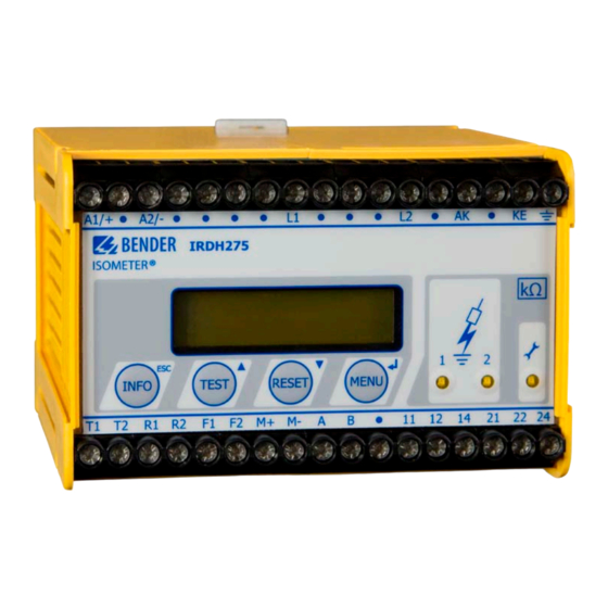
6. Bedienung und Einstellung 6.1 Bedienelemente und Anzeigen IRDH275(B) INFO-Taste: Abfragen von Standardinformation / ESC-Taste: Zurück (Menü-Funktion), Bestätigung Parameteränderung TEST-Taste: Selbsttest aufrufen/ Aufwärts-Taste: Parameteränderung, im Menü aufwärts bewegen RESET-Taste: Löschen gespeicherter Isolationsfehler-Alarme Abwärts-Taste: Parameteränderung, im Menü abwärts bewegen Menü-Taste: Aufruf Menüsystem Eingabe-Taste: Bestätigung Parameteränderung Alarm-LED 1 leuchtet: Isolationsfehler, erste Warnschwelle erreicht Alarm-LED 2 leuchtet: Isolationsfehler, zweite Warnschwelle erreicht... -
Page 42: Display Im Standard-Betrieb
Bedienung und Einstellung 6.1.1 Display im Standard-Betrieb Anzeige des Isolationswiderstands in kΩ Zusätzlicher Hinweis zum Isolationswiderstand: „+“ = Isolationsfehler an L+ „–“ = Isolationsfehler an L– „s“ = neue Messung hat begonnen = Polarität des Messpulses = gültiger BMS-Busverkehr = Neuer Eintrag im Historienspeicher = blinkend, wenn Uhr einzustellen ist Meldungen: - Isolation Fehler... -
Page 43: Display Im Menü-Betrieb
(Anzeige nur bei Isolationswerten > 20 kΩ) • Setup Status (Die Bedeutung der Status-Nummer kann aus der Statustabelle auf Seite 85 entnommen werden • COM-Setup (eigene Busadresse) Die oben genannten Informationen sollten im Problemfall notiert werden und bei Rückfragen an Bender vorliegen. IRDH275_D00122_03_M_XXDE/05.2017... - Page 44 Bedienung und Einstellung Mit der TEST-Taste wird die Selbsttestfunk- tion des ISOMETER®s gestartet. Mit der RESET-Taste werden im ISOMETER® gespeicherte Isolationsfehler-Alarme zu- rückgesetzt. Die Speicher-Funktion ist nur verfügbar, wenn zuvor der Fehlerspeicher im Menü ISO-Setup eingeschaltet wurde oder die Klemmen R1/R2 gebrückt waren. Außerdem lässt sich der Feh- lerspeicher des ISOMETER®s nur dann zurücksetzen, wenn der gemessene Iso- lationswert mindestens 25 % höher liegt, als der eingestellte Ansprechwert.
-
Page 45: Menüstruktur Und Menübetrieb
Bedienung und Einstellung EINGABE-Taste Auswahl eines Menüpunktes oder Unter-Menüpunkts, Bestätigung und Speicherung einer Parameteränderung mit Rücksprung zum zugehörigen Unter-Menüpunkt oder Sprung zum nächsten Eingabefeld. ESC-Taste: Rücksprung zur übergeordneten Menüebene. Wird das Menü nicht beendet, schaltet das Gerät nach ca. 5 Minuten wieder in den Standard-Betrieb. In den nachfolgenden Menü-Diagrammen werden zwecks übersichtlicherer Darstellung für EINGABE, Aufwärts/Abwärts und ESCAPE nur die folgenden Symbole verwendet:... - Page 46 Bedienung und Einstellung Navigieren im Menü Mit Hilfe der Aufwärts/Abwärts-Tasten wählt man den gewünschten Menü- punkt aus. Die Auswahl wird durch einen blinkenden Cursor angezeigt. Durch Betätigen der EINGABE-Taste wird das zum Menüpunkt gehörende Unterme- nü aufgerufen. Auch in den Untermenüs werden die gewünschten Parameter mit den Auf- wärts/Abwärts-Tasten ausgewählt.
-
Page 47: Diagramm Menüstruktur
Bedienung und Einstellung 6.2.1 Diagramm Menüstruktur IRDH275_D00122_03_M_XXDE/05.2017... -
Page 48: Menü History Info (Irdh275B)
Bedienung und Einstellung 6.3 Menü HISTORY INFO (IRDH275B) In der Datenbank des Historienspeichers können 99 Ereignisse mit Datum und Uhrzeit gespeichert werden. Die Datenbank ist als Ringspeicher ausgeführt, d.h. der älteste Eintrag wird überschrieben. Die Daten werden in einen nicht- flüchtigen Speicher geschrieben und sind somit auch gegen Spannungsaus- fall geschützt. -
Page 49: Diagramm History Info (Irdh275B)
Bedienung und Einstellung 6.3.1 Diagramm HISTORY INFO (IRDH275B) IRDH275_D00122_03_M_XXDE/05.2017... -
Page 50: Menü Iso Setup: Einstellen Der Isometer® -Grundfunktionen
Bedienung und Einstellung 6.4 Menü ISO SETUP: Einstellen der ISOMETER® - Grundfunktionen Mit diesem Menüpunkt werden die Alarm-Meldungen Alarm1 und Alarm2 (Vorwarnung und Hauptmeldung), die Arbeitsweise der Alarm-Relais K1 und K2 (N.O = Arbeitsstromschaltung, N.C = Ruhestromschaltung) und die Fehler- speicherung eingestellt. - Page 51 Bedienung und Einstellung K1: N.C Test = Ruhestromschaltung Kontakte 11-12-14, mit Relaistest (das Alarm-Relais ist im Normalbetrieb angezogen) K1: N.O Test = Arbeitsstromschaltung Kontakte 11-12-14, mit Relaistest (das Alarm-Relais ist im Normalbetrieb nicht angezogen) K1: N.C = Ruhestromschaltung Kontakte 11-12-14, ohne Relaistest (das Alarm-Relais ist im Normalbetrieb angezogen) K1: N.O = Arbeitsstromschaltung Kontakte 11-12-14, ohne Relaistest...
- Page 52 Bedienung und Einstellung Diagramm ISO SETUP IRDH275_D00122_03_M_XXDE/05.2017...
-
Page 53: Memory-Einstellung (On/Off)
Bedienung und Einstellung Während des automatischen Selbsttests werden die Alarm- Relais nicht umgeschaltet. Bei Defekt des ISOMETER®s wird das Relais K2 automatisch als Gerätefehler-Relais aktiviert. 6.4.3 Memory-Einstellung (on/off) Memory: on = Fehlerspeicherung ist eingeschaltet Nach Beseitigung der Fehlerursache muss das Gerät mit der RESET-Taste zurückgesetzt werden. -
Page 54: Menü Iso Advanced: Einstellen Der Erweiterten Funktionen
Bedienung und Einstellung 6.5 Menü ISO ADVANCED: Einstellen der erweiterten Funktionen 6.5.1 Externe Ankoppelgeräte (AGH: no) Einstellung „no“, wenn kein Ankoppelgerät verwendet wird (Werkseinstel- lung). AGH: 204 AK80 Das IRDH275 wird mit der Klemme AK an die Klemme AK80 des AGH204S-4 angeschlossen. -
Page 55: Netzableitkapazität Anpassen (Cemax: 150 Μf)
Bedienung und Einstellung 6.5.2 Netzableitkapazität anpassen (Cemax: 150 μF) Hiermit kann das ISOMETER® an die max. Netzableitkapazität angepasst wer- den (max. 500 μF). Bitte beachten Sie, dass sich bei der Einstellung C = 500 μF die Grundmesszeit auf ca. 10 s erhöht. Werkseinstellung = 150 μF 6.5.3 Messverfahren von AMP auf DC umschalten... -
Page 56: Startzeit Des Automatischen Selbsttests Festlegen (Test)
Bedienung und Einstellung 6.5.7 Startzeit des automatischen Selbsttests festlegen (Test) (IRDH275B) Ist im Unter-Menü ISO ADVANCED der 24 h-Selbsttest aktiviert, kann mit Hilfe des Menüpunkts „TEST: 12:00“ ein Zeitpunkt für die Ausführung des Selbsttest eingestellt werden. Danach wird der Selbsttest automatisch einmal am Tag zur angegebenen Zeit gestartet. -
Page 57: Diagramm Iso Advanced
Bedienung und Einstellung 6.5.8 Diagramm ISO ADVANCED IRDH275_D00122_03_M_XXDE/05.2017... -
Page 58: Menü Com Setup: Einstellen Der Bms-Schnittstelle
Bedienung und Einstellung 6.6 Menü COM SETUP: Einstellen der BMS-Schnittstelle 6.6.1 Busadresse „Addr:“ (IRDH275B) Mit Hilfe dieses Menüpunktes wird die BMS-Busadresse des IRDH275B einge- stellt. Es ist darauf zu achten, dass keine Busadresse doppelt vergeben wird. Werksseitig ist Adresse 3 eingestellt, hierdurch arbeitet das Gerät als Slave. Funktionsstörungen durch falsche Adressvergabe! Werden mehrere ISOMETER®... -
Page 59: Iso-Monitor (Irdh275B)
Bedienung und Einstellung 6.6.3 ISO-Monitor (IRDH275B) Mit dieser Funktion ist es möglich, von allen busfähigen ISOMETER®n im BMS- Netzwerk, deren aktuell gemessenen Isolationswert sowie evtl. vorhandene Meldungen abzufragen. Nach Auswahl der Busadresse werden die Informati- onen, die das selektierte Gerät gespeichert hat, auf dem Display angezeigt. Die Monitoranzeige ist ähnlich wie die Standardanzeige aufgebaut, statt des Messpulses wird aber die ausgewählte Busadresse angezeigt. -
Page 60: Diagramm Com Setup (Irdh275B)
Bedienung und Einstellung 6.6.4 Diagramm COM SETUP (IRDH275B) IRDH275_D00122_03_M_XXDE/05.2017... -
Page 61: Menü Password
Bedienung und Einstellung 6.7 Menü PASSWORD 6.7.1 Passwort einstellen und aktivieren Mit diesem Menüpunkt kann eine „Password“-Abfrage aktiviert werden. Da- mit kann das ISOMETER® gegen unbefugte Änderungen der Einstellungen ge- schützt werden. Mit den AUFWÄRTS/ABWÄRTS-Tasten kann man das gewünschte Passwort (Menüpunkt „2. -
Page 62: Diagramm Passwort
Bedienung und Einstellung 6.7.2 Diagramm PASSWORT IRDH275_D00122_03_M_XXDE/05.2017... -
Page 63: Menü Language (Sprache)
Bedienung und Einstellung 6.8 Menü LANGUAGE (Sprache) 6.8.1 Einstellung der Sprache Mit Hilfe des Menüpunkts „Language“ können die Fehlermeldungen des ISOMETER®s auf verschiedene Sprachen eingestellt werden. Zur Auswahl ste- hen „Deutsch“ oder „English“. Das Geräte-Menü wird von der Sprach-Einstel- lung nicht berührt. 6.8.2 Diagramm Language (Sprache) IRDH275_D00122_03_M_XXDE/05.2017... -
Page 64: Menü Service
Bedienung und Einstellung 6.9 Menü SERVICE Dieser Menüpunkt ist für das Bender-Servicepersonal vorgesehen und durch ein Passwort gegen irrtümliche Falscheinstellungen gesichert. Er dient bei ei- nem eventuell auftretenden Fehler des Gerätes der schnellen und fachge- rechten Fehlerbeseitigung. 6.10 Parametrieren über das Internet Sie können die nachfolgend angegebenen Parameter eines IRDH275B mittels... -
Page 65: Serielle Schnittstellen
Zur Auswertung der Daten mittels PC oder Laptop wird die Terminal-Software „IsoData“ und ein Schnittstellen-Konverter ASCII-RS485/RS232 benötigt. Um die Software zu erhalten, kontaktieren Sie den Bender Service, siehe Seite 8. Daten der Schnittstelle: • RS485-Schnittstelle galvanisch getrennt von der Geräte-Elektronik •... - Page 66 Serielle Schnittstellen IRDH275_D00122_03_M_XXDE/05.2017...
-
Page 67: Rs485-Schnittstelle Mit Bms-Protokoll (Irdh275B)
Serielle Schnittstellen 7.2 RS485-Schnittstelle mit BMS-Protokoll (IRDH275B) Die von Geräteelektronik und Stromausgang galvanisch getrennte RS485- Schnittstelle dient als physikalisches Übertragungsmedium für das BMS-Bus- protokoll. Wenn mehrere IRDH275B oder andere busfähige Geräte über den BMS-Bus zu einem Netzwerk verbunden werden, muss der BMS-Bus an seinen beiden Enden mit Abschlusswiderständen von jeweils 120 Ω... -
Page 68: Topologie Rs485-Netzwerk (Irdh275B)
Geschirmte Leitung, Ader-Durchmesser ≥ 0,6 mm (z.B. J-Y(St)Y 2x0,6), Schirm einseitig an Erde (PE). Anschluss an die Klemmen A und B. Die maximale Bus-Teilnehmerzahl ist auf 32 Geräte beschränkt. Sollen weitere Geräte angeschlossen werden, hält Bender hierfür den Schnittstellenverstär- ker DI1 bereit. IRDH275_D00122_03_M_XXDE/05.2017... -
Page 69: Bms-Protokoll (Irdh275B)
Serielle Schnittstellen 7.4 BMS-Protokoll (IRDH275B) Dieses Protokoll ist wesentlicher Bestandteil der Bender-Messgeräte-Schnitt- stelle (BMS-Busprotokoll). Die Datenübertragung erfolgt mit ASCII-Zeichen. Die Schnittstellendaten sind: • Baudrate: 9600 Baud • Übertragung: 1 Startbit, 7 Datenbits, 1 Paritätsbit, 1 Stoppbit (1, 7, E, 1) •... -
Page 70: Bms-Slave
Serielle Schnittstellen Folgende Fehlerursachen könnten vorliegen: • Adressen doppelt vergeben • ein zweiter Master befindet sich im BMS-Bus • Störsignale auf den Busleitungen • Defektes Gerät ist am Bus angeschlossen • Terminierungswiderstände nicht eingeschaltet 7.4.2 BMS-Slave Die Werkseinstellung aller IRDH275B ist Slave-Betrieb (Adresse 3). In einem BMS-Netzwerk muss für jeden Slave eine eigene Adresse zwischen 2…30 ein- gestellt werden. -
Page 71: Inbetriebnahme Rs485-Netzwerk Mit Bms-Protokoll
Serielle Schnittstellen Die folgende Tabelle gibt einen Überblick über die wichtigsten Alarmmeldun- gen und die Zuordnung der Meldung bei Ausgabe über Display und Bedien- tableaus, z. B. PRC1470. Meldung Kanal Bemerkung Isolation Fehler Isolationswiderstand < Einstellwert Alarm 1 Isolation Fehler Isolationswiderstand <... - Page 72 Serielle Schnittstellen BMS-Bus-Adressbereiche Adressen* Gerät Bemerkung Es gibt kein Gerät mit der Adresse 0 ! Informationen, die an die Adresse 0 gesendet werden, gelten für alle an die Schnittstellen angeschlossenen Geräte (Broadcast) 1 PRC1470 Steuer- und Anzeigegerät IRDH275B/ 1…30 Isolationsüberwachungsgeräte 375B/575 1…30 COM465 Protokollwandler...
-
Page 73: Werkseinstellungen
8. Werkseinstellungen Menü Untermenü Werkseinstellung 1. EXIT 2. HISTORY INFO 3. ISO SETUP 1. Exit 2. Alarm1: 40 kΩ 3. Alarm2: 10 kΩ 4. K1: N.O Test 5. K2: N.O Test 6. Memory: 7. M+/M-:* 0-20 mA* 4. ISO ADVANCED 1. - Page 74 Werkseinstellung 3. Status: 7. LANGUAGE 1. Exit 2. Text: Deutsch 8. SERVICE (Zugang nur für Bender-Servicepersonal) * Einstellungen gelten nur für das IRDH275B. Bitte überprüfen Sie, ob die Grundeinstellung des ISOMETER®s den Anforde- rungen des zu überwachenden IT-Systems entspricht. IRDH275_D00122_03_M_XXDE/05.2017...
-
Page 75: Technische Daten Irdh275(B)
9. Technische Daten IRDH275(B) 9.1 Tabellarische Daten Die mit * gekennzeichneten Angaben sind Absolutwerte Isolationskoordination nach IEC 60664-1 Bemessungsspannung ............................. AC 800 V Bemessungsstoßspannung/Verschmutzungsgrad ................... 8 kV / 3 Spannungsbereiche IRDH275… : Netznennspannung U ..................... AC / 3/(N) AC 0…793 V* Nennfrequenz f <... - Page 76 Technische Daten IRDH275(B) Messkreis .............................. ≤ 50 V Messspannung U = 0 Ω).......................... ≤ 280 μA Messstrom I (bei R ............................ ≥ 180 kΩ Innenwiderstand DC R bei 50 Hz............................. ≥ 180 kΩ Impedanz Z ......................≤ DC 1200 V Zulässige Fremdgleichspannung U ........................
- Page 77 Technische Daten IRDH275(B) Schaltglieder Schaltglieder ................2 Wechsler: K1 (Alarm 1), K2 (Alarm 2, Gerätefehler) Arbeitsweise K1, K2 (Alarm 1 / Alarm 2) .............. Arbeits- oder Ruhestromschaltung Werksseitige Einstellung (Alarm 1 / Alarm 2)................Arbeitsstromschaltung Elektrische Lebensdauer........................12 000 Schaltspiele Kontaktklasse..........................
- Page 78 Technische Daten IRDH275(B) Software-Version IRDH275B ......................... D159 V1.8 Gewicht ................................ca. 510 g Option „W“ Schockfestigkeit nach IEC 60068-2-27 (Gerät in Betrieb)................. 30 g / 11 ms Dauerschocken nach IEC 60068-2-29 (Transport) ..................40 g / 6 ms Schwingungsbeanspruchung IEC 60068-2-6................1,6 mm / 10…25 Hz ................................
-
Page 79: Normen, Zulassungen Und Zertifizierungen
Technische Daten IRDH275(B) 9.2 Normen, Zulassungen und Zertifizierungen Das ISOMETER® wurde unter Beachtung folgender Normen entwickelt: - DIN EN 61557-8 (VDE 0413-8):2007-12 - IEC 61557-8:2007 + Corrigendum 2007-05 - IEC 61326-2-4:2006-06 Ed. 1.0 - DIN EN 60664-1 (VDE 0110-1):2008-01 - DIN EN 60664-3 (VDE 0110-3):2003-09 - ASTM F1669M-96(2007) - ASTM F1207M-96(2007) IRDH275_D00122_03_M_XXDE/05.2017... -
Page 80: Kennlinien
Technische Daten IRDH275(B) 9.3 Kennlinien ISOMETER®-Ansprechzeiten in Abhängigkeit von den Ableitkapa- zitäten: = 1…500 μF, U = 0…793 V / 50 Hz 1000 ≤ Ω 10 M ≥ Ω 1000 [μF] IRDH275_D00122_03_M_XXDE/05.2017... - Page 81 Technische Daten IRDH275(B) Max. Wechselspannung zwischen IT-System und PE im Frequenz- bereich < 50 Hz IRDH275_D00122_03_M_XXDE/05.2017...
- Page 82 Technische Daten IRDH275(B) Stromausgang 0…400 μA (nur IRDH275) μ Ω Ω = Isolationsfehler in kΩ I = Stromausgang in mA IRDH275_D00122_03_M_XXDE/05.2017...
- Page 83 Technische Daten IRDH275(B) Stromausgang 0…20 mA (IRDH275B) Ω Ω = Isolationsfehler in kΩ I = Stromausgang in mA IRDH275_D00122_03_M_XXDE/05.2017...
- Page 84 Technische Daten IRDH275(B) Stromausgang 4…20 mA (IRDH275B) Ω Ω = Isolationsfehler in kΩ I = Stromausgang in mA IRDH275_D00122_03_M_XXDE/05.2017...
- Page 85 Technische Daten IRDH275(B) Statusnummer IRDH275_D00122_03_M_XXDE/05.2017...
- Page 86 Technische Daten IRDH275(B) Gehäusemaßbild IRDH275(B) • Schnellbefestigung auf Hutprofilschiene nach DIN EN 60715 / IEC 60715 oder • Schraub-Befestigung mittels einzuschiebender trapezförmiger Halterung Bestell-Nr.: B990056 (Option W) IRDH275_D00122_03_M_XXDE/05.2017...
-
Page 87: Bestellangaben
Technische Daten IRDH275(B) 9.4 Bestellangaben 9.4.1 ISOMETER® Nennspg. Versorg.-Spg. Art.-Nr. IRDH275-435 3(N) AC 0…793 V AC 88…264 V B91065100 DC 0…650 V DC 77…286 V IRDH275W-435 „ „ B91065100W IRDH275B-435 „ „ B91065101 IRDH275BW-435 „ „ B91065101W IRDH275-427 AC 19,2…55 V B91065104 DC 19,2…72 V 42…460 HZ... -
Page 88: Ankoppelgeräte
Technische Daten IRDH275(B) Option W Die Geräte mit der Endung „W“ entsprechen erhöhter Schock- und Rüttelfes- tigkeit. Durch eine besondere Lackierung der Elektronik wird ein höherer Schutz gegen mechanische Belastung und gegen Feuchtigkeit erreicht. Dies ermöglicht den Einsatz der Geräte auf Schiffen, in Schienenfahrzeugen und auch in erdbebengefährdeten Gebieten. -
Page 89: Index
50 Arbeiten an elektrischen Anlagen 13 Funktionsbeschreibung 20 Arbeitsweise Alarm-Relais einstellen 50 Automatischer Selbsttest, Einstellung 55 Gehäusemaßbild 86 Gerätefehler-LED 22 Bender-Messgeräte-Schnittstelle (BMS) 69 Benutzungshinweise 7 Bestellangaben 87 Historienspeicher 48 Bestimmungsgemäße Verwendung 16 Blinkender Punkt 70 BMS-Adressen 72 Inbetriebnahme BMS-Netzwerk 71... - Page 90 Kennlinien 80 RESET-Taste 21 Kurzanleitung 17 RS485-Netzwerk - Falsche Verlegung 68 - Richtige Verlegung 68 Menü RS485-Schnittstelle 67 - COM SETUP 58 - HISTORY INFO 49 - ISO ADVANCED 54 Schnittstellen 65 - ISO SETUP 50 Schulungen 10 - LANGUAGE (Sprache) 63 Selbsttest, Isometer 41 - PASSWORD 61 Serie ...B...
- Page 91 Werkseinstellungen 73 Zulassungen 79 IRDH275_D00122_03_M_XXDE/05.2017...
- Page 92 Bender GmbH & Co. KG Londorfer Str. 65 • 35305 Grünberg • Germany Postfach 1161 • 35301 Grünberg • Germany Tel.: +49 6401 807-0 Fax: +49 6401 807-259 E-Mail: info@bender.de Web: http://www.bender.de Fotos: Bender Archiv.
- Page 93 Manual ISOMETER®IRDH275 IRDH275B Insulation monitoring device for IT AC systems with galvanically connected rectifiers and converters and for IT DC systems Software version IRDH275: D0160 V1.8 IRDH275_D00122_03_M_XXEN/05.2017...
- Page 94 Bender GmbH & Co. KG Londorfer Str. 65 • 35305 Grünberg • Germany Postfach 1161 • 35301 Grünberg • Germany Tel.: +49 6401 807-0 Fax: +49 6401 807-259 Email: info@bender.de Web: http://www.bender.de © Bender GmbH & Co. KG All rights reserved.
- Page 95 Table of Contents 1. Important information ..................7 How to use this manual ................. 7 Technical support: service and support ........... 8 1.2.1 First level support ..................... 8 1.2.2 Repair service ..................... 8 1.2.3 Field service ......................9 Training courses ..................... 10 Delivery conditions ..................
- Page 96 Table of Contents 4. Connection ..................... 29 Wiring ........................ 29 Wiring diagrams with coupling devices ..........32 4.2.1 Connection with AGH150W-4 ..............32 4.2.2 Connection with AGH520S ................ 33 4.2.3 Connection with AGH204S-4 ..............34 5. Commissioning flow chart (threepart) ............37 6.
- Page 97 Table of Contents 6.5.6 Setting the date (Date) (IRDH275B) ............55 6.5.7 Specifying the starting time of the automatic self test (Test) (IRDH275B) ....................... 56 6.5.8 Diagram ISO ADVANCED ................57 Menu COM SETUP: Setting the BMS interface ........58 6.6.1 Bus address „Addr:“...
- Page 98 Table of Contents 9. Technical data IRDH275(B) ................75 Data in tabular form ..................75 Standards, approvals and certifications ..........79 Characteristic curves ..................80 Ordering details ..................... 87 9.4.1 ISOMETER® ....................... 87 9.4.2 Coupling devices ................... 88 9.4.3 Measuring instruments ................88 INDEX ........................
-
Page 99: Important Information
1. Important information 1.1 How to use this manual This manual is intended for qualified personnel working in electrical engineering and electronics! Always keep this manual within easy reach for future reference. To make it easier for you to understand and revisit certain sections in this man- ual, we have used symbols to identify important instructions and information. -
Page 100: Technical Support: Service And Support
Important information This manual has been compiled with great care. It might nevertheless contain errors and mistakes. Bender cannot accept any liability for injury to persons or damage to property resulting from errors or mistakes in this manual. 1.2 Technical support: service and support For commissioning and troubleshooting Bender offers you: 1.2.1... -
Page 101: Field Service
Please send the devices for repair to the following address: Bender GmbH, Repair-Service, Londorfer Str. 65, 35305 Grünberg 1.2.3 Field service On-site service for all Bender products • Commissioning, configuring, maintenance, troubleshooting of Bender products • Analysis of the electrical installation in the building (power quality test, EMC test, thermography) •... -
Page 102: Training Courses
ZVEI (Zentralverband Elektrotechnik- und Elektronikindustrie e. V.) (German Electrical and Electron- ic Manufacturer's Association) also applies. Sale and delivery conditions can be obtained from Bender in printed or elec- tronic format. 1.5 Inspection, transport and storage Inspect the dispatch and equipment packaging for damage, and compare the contents of the package with the delivery documents. -
Page 103: Warranty And Liability
Important information 1.6 Warranty and liability Warranty and liability claims in the event of injury to persons or damage to property are excluded if they can be attributed to one or more of the follow- ing causes: • Improper use of the device. •... -
Page 104: Disposal
13 August 2005 must be taken back by the manufacturer and disposed of properly. For more information on the disposal of Bender devices, refer to our homepage at www.bender-de.com -> Service & support. -
Page 105: Safety Instructions
2. Safety instructions 2.1 General safety instructions Part of the device documentation in addition to this manual is the enclosed "Safety instructions for Bender products". 2.2 Work activities on electrical installations Only qualified personnel are permitted to carry out the work necessary to install, commission and run a device or system. -
Page 106: Device-Specific Safety Information
Safety instructions 2.3 Device-specific safety information Children and unauthorised persons must not have access to or contact with the ISOMETER®. WARNING Make sure that the operating voltage is correct! Prior to insulation and voltage tests, the ISOMETER® must be disconnected from the IT system for the duration of the test. In order to check the correct connection of the device, a CAUTION functional test has to be carried out before starting the... - Page 107 Safety instructions When using ISOMETER®s in IT systems, make sure that only one active ISOMETER® is connected in each interconnected system. If IT systems are interconnected via coupling switches, make sure that ISOMETER®s not currently used are disconnected from the IT system and deactivated. IT systems coupled via diodes or capacitances may also influence the insulation monitoring process so that a central control of the different ISOMETER®s is required.
-
Page 108: Intended Use
Safety instructions 2.4 Intended use The ISOMETER® is intended for: • monitoring the insulation resistance of IT systems Use for the intended purpose also includes • compliance with all information in the operating instructions, and • compliance with test intervals. In order to meet the requirements of the applicable standards, customised pa- rameter settings must be made on the equipment in order to adapt it to local equipment and operating conditions. -
Page 109: Directions For Installation
Safety instructions 2.5 Directions for installation Risk of property damage due to unprofessional installation! If more than one insulation monitoring device is connected to a conductively connected system, the system can be damaged. If several devices are connected, the device does CAUTION not function and does not signal insulation faults. - Page 110 Safety instructions Prevent measurement errors! When an AC system being monitored contains galvanically coupled DC circuits, take into consideration that: an insulation fault can only be detected correctly when the rectifier valves carry a minimum current of 5…10 mA. IRDH275_D00122_03_M_XXEN/05.2017...
-
Page 111: Function
Memory with real-time clock to store all alarm messages with date and time stamp. • BMS interface (BMS protocol) for data exchange with other Bender devices (RS485 electrically isolated). • Internal disconnection of the ISOMETER from the IT system to be moni- tored (using a control signal;... -
Page 112: Product Description
Suitable coupling devices are available to extend the nominal voltage range U The IRDH275B can be used in combination with a control and indicating de- vice, e.g. PRC1470 version 2 or higher, on the BMS (BMS = Bender Measuring Device Interface) bus. - Page 113 0…400 μA or 0/4…20 mA (IRDH275B) at M+/M- are galvanically isolated. measuring principle "adaptive measuring pulse", a measuring principle developed by Bender (European Patent: EP 0 654 673 B1). Self test A self test can be carried out manually using the TEST button or automatically.
- Page 114 Function When a device error or connection fault is found, the message "!Error!" ap- pears on the display, the device fault LED lights up, the relay K2 (21-22-24) switches and the respective fault message (see table) is indicated. If such a de- vice fault occurs, a self test is started again every minute.
- Page 115 Press TEST button 2. Switch the supply voltage off and on 3. Contact Bender If the on/off switching of the supply voltage is not possible for technical reasons, a RESET of the process control can be carried out by pressing the "INFO“, "RESET“ and "MENU“ key.
-
Page 116: Additional Functions Irdh275B
Function 3.5 Additional functions IRDH275B Current output for external measuring instrument The current output of IRDH275B provides 0(4)…20 mA. The current output is galvanically isolated from the device electronics and the RS485 interface. The ISO SETUP menu, on page 50, allows to switch over between 0…20 mA and 4…20 mA. - Page 117 Function Function input F1/F2 for connection or disconnection of IT systems being monitored The ISOMETER® can be disconnected from the IT system and set to STANDBY mode with the function input F1/F2. If the input F1/F2 is bridged, the connec- tions L1/L2 are switched off via internal coupling relays, the measuring func- tion is stopped and the message "STANDBY"...
- Page 118 Function IRDH275_D00122_03_M_XXEN/05.2017...
- Page 119 Function ISOnet Function (COM SETUP) Select "ISOnet=ON" from the COM SETUP menu to activate this function. This function is a type of scanning function. The BMS Master activated via the ISOnet function controls the ISOnet slave devices via the BMS bus. Once an ISOMETER®...
- Page 120 Function IRDH275_D00122_03_M_XXEN/05.2017...
-
Page 121: Connection
4. Connection Only qualified personnel are permitted to carry out the work necessary to install, commission and run a device or system. Risk of electrocution due to electric shock! Touching live parts of the system carries the risk of: • An electric shock •... - Page 122 Connection Only one ISOMETER® may be connected to an external TEST or RESET button. A galvanic parallel connection of several TEST and RESET inputs for collective testing of ISOMETER®s is not permitted. External coupling devices connected via the terminal AK cannot be switched off via the internal coupling relays.
- Page 123 Connection Legend to wiring diagram: Supply voltage U (see nameplate) via 6 A fuse For UL and CSA applications, the use of 5 A fuses is mandatory 2, 3 Connection to the 3AC system to be monitored: connect terminals L1, L2 to neutral conductor N or terminals L1, L2 to conductor L1, L2 Connection to the AC system to be monitored: connect terminals L1, L2 to conductor L1, L2...
-
Page 124: Wiring Diagrams With Coupling Devices
Connection 4.2 Wiring diagrams with coupling devices Please observe the settings in the "ISO ADVANCED AGH“ menu ! Adapt the settings to the coupling device to be used. 4.2.1 Connection with AGH150W-4 Connected to the ISOMETER® this coupling device extends the nominal volt- age range to DC 1760 V in DC systems. -
Page 125: Connection With Agh520S
Connection 4.2.2 Connection with AGH520S Connected to the ISOMETER® this coupling device extends the nominal volt- age range to AC 7200 V in pure AC systems. In case of 3 AC systems, Pin 2 of AGH520S must be connected to L1, in case of 3/N/AC systems, Pin 2 must be connected to the N conductor. -
Page 126: Connection With Agh204S-4
Connection 4.2.3 Connection with AGH204S-4 This coupling device extends the nominal voltage range of ISOMETER®s used in AC systems including rectifiers. 1 without rectifiers = 3AC 0….1650 V (DC max. 1000 V) = 3AC 0….1300 V (max. AC voltage; max. DC vol- 2 with rectifiers tage after rectifiers in intermediate circuits of fre- quency converters:1840 V) - Page 127 Connection The maximum DC voltage is the voltage permitted to occur in the AC part of an IT system to PE when the IRDH275 is coupled with AGH204S-4 in this part of the system. This voltage is dependent on the level of the nominal voltage, the type of rectification 6 pulse, 12 pulse,…), the type of converter intermedi- ate circuit (current…...
- Page 128 Connection IRDH275_D00122_03_M_XXEN/05.2017...
-
Page 129: Commissioning Flow Chart (Threepart)
5. Commissioning flow chart (threepart) The encircled figures in the flow chart correspond to the figures in the legend to the wiring diagram. Commissioning of the ISOMETER® (1) IRDH275_D00122_03_M_XXEN/05.2017... - Page 130 Commissioning flow chart (threepart) Commissioning of the ISOMETER® (2) IRDH275_D00122_03_M_XXEN/05.2017...
- Page 131 Commissioning flow chart (threepart) Commissioning of the ISOMETER® (3) In order to check the proper connection, a functional test using a resistance that is suitable for the mains voltage is to be carried out. Size of the resistance: 50% of the present response value Alarm2.
- Page 132 Commissioning flow chart (threepart) IRDH275_D00122_03_M_XXEN/05.2017...
-
Page 133: Operation And Setting
6. Operation and setting 6.1 Operating features and displays IRDH275(B) INFO key: to query standard information / ESC key: back (menu function), confirmation parameter change TEST button: to call up the self test / Up key: parameter change, moving up in the menu RESET button: to delete insulation fault alarms Down key: parameter change, moving down in the menu MENU key: to activate the menu system /... -
Page 134: Display In The Standard Mode
Operation and setting 6.1.1 Display in the standard mode Indication of the insulation resistance in kΩ Additional information about the insulation resistance: "+" = insulation fault at L+ "–" = insulation fault at L– "s" = new measurement has started = polarity of the measuring pulse = valid bus communication signals = new entry in the memory data base... -
Page 135: Display In The Menu Mode
• Setup status (for details refer to the table of the status numbers on page 85) • COM-Setup (IRDH275 bus address) Please have the details above on hand if you have a problem and if you con- tact Bender for technical questions. IRDH275_D00122_03_M_XXEN/05.2017... - Page 136 Operation and setting Activating the TEST button starts the ISOMETER® self test. Pressing the RESET button resets insula- tion fault alarms stored in the ISOMETER®. The memory function is only available af- ter activating the fault memory in the ISO SETUP menu or after bridging the terminals R1/R2.
- Page 137 Operation and setting ENTER key Selecting a menu item or sub menu item, confirming or stor- ing a parameter change and going back to the associated sub menu item or going to the next input area. ESC key: Returning from a sub menu to the previous menu. If you do not quit the menu, the device automatically returns to the standard mode again after approximately five minutes.
-
Page 138: Menu Structure And Menu Mode
Operation and setting 6.2 Menu structure and menu mode Switchover to the menu mode After pressing the MENU key, you can change from the standard mode to the menu mode. From the menu mode you can link to the different sub menus. Navigation within the menu Select the desired menu item using the UP/DOWN keys. -
Page 139: Diagram Menu Structure
Operation and setting 6.2.1 Diagram menu structure IRDH275_D00122_03_M_XXEN/05.2017... -
Page 140: Menu History Info (Irdh275B)
Operation and setting 6.3 Menu HISTORY INFO (IRDH275B) 99 events with date and time stamp can be stored in the memory database. The database is designed as a ring memory, i.e. the eldest entry is overwritten. Data is written into a non-volatile memory and therefore provides protection against voltage failure. -
Page 141: Diagram History Info (Irdh275B)
Operation and setting 6.3.1 Diagram HISTORY INFO (IRDH275B) IRDH275_D00122_03_M_XXEN/05.2017... -
Page 142: Menu Iso Setup: Setting Of The Basic Isometer® Functions
Operation and setting 6.4 Menu ISO SETUP: Setting of the basic ISOMETER® functions All alarm functions such as Alarm 1 and Alarm 2 (prewarning and main alarm), the operating principle of the alarm relays K1 and K2 (N.O = N/O operation, N.C = N/C operation) and the fault storage behaviour are set in this menu. - Page 143 Operation and setting K1: N.C Test = N/C operation contacts 11-12-14, with relay test (the alarm relay is energized during normal operation) K1: N.O Test = N/O operation contacts 11-12-14, with relay test (the alarm relay is deenergized during normal operation) K1: N.C = N/C operation contacts 11-12-14, without relay test (the alarm relay is energized during normal operation)
- Page 144 Operation and setting Diagram ISO SETUP IRDH275_D00122_03_M_XXEN/05.2017...
-
Page 145: Memory Setting (On/Off)
Operation and setting During the automatic self test, the alarm relays are not switched over. When a device fault occurs at the ISOMETER®, the relay K2 will automatically be activated as a device fault relay. 6.4.3 Memory setting (on/off) Memory: on = Fault memory is activated The device must be reset with the RESET button after clearing the fault. -
Page 146: Menu Iso Advanced: Setting Of The Extended Functions
Operation and setting 6.5 Menu ISO ADVANCED: Setting of the extended functions 6.5.1 External coupling devices (AGH: no) Basic setting "no", when no coupling device is used (factory setting). AGH: 204 AK80 Terminal AK of the IRDH275 is connected to terminal AK80 of the AGH204S-4. -
Page 147: Adaptation To The System Leakage Capacitance
Operation and setting 6.5.2 Adaptation to the system leakage capacitance (Cemax: 150 μF) This menu allows to adapt the ISOMETER® to the maximum system leakage capacitance (max. 500 μF). Please note that the basic measuring time will be increased to approximately 10 seconds when the setting is C = 500 μF. -
Page 148: Specifying The Starting Time Of The Automatic Self Test (Test) (Irdh275B)
Operation and setting 6.5.7 Specifying the starting time of the automatic self test (Test) (IRDH275B) If the 24h self test is activated in the ISO ADVANCED menu, it is possible to set the time (hour) when the self test is to be carried out by means of the "TEST: 12:00"... -
Page 149: Diagram Iso Advanced
Operation and setting 6.5.8 Diagram ISO ADVANCED IRDH275_D00122_03_M_XXEN/05.2017... -
Page 150: Menu Com Setup: Setting The Bms Interface
Operation and setting 6.6 Menu COM SETUP: Setting the BMS interface 6.6.1 Bus address „Addr:“ (IRDH275B) This menu item is used to set the BMS bus address of the IRDH275. Since there are several ISOMETERs in one system, take care that the bus address is not as- signed twice. -
Page 151: Iso Monitor (Irdh275B)
Operation and setting 6.6.3 ISO monitor (IRDH275B) This function allows to query the current measured value as well as the mes- sages of all bus-capable ISOMETERs existing in the BMS network. After select- ing the bus address, the entire information stored by the selected device is indicated on the display. -
Page 152: Diagram Com Setup (Irdh275B)
Operation and setting 6.6.4 Diagram COM SETUP (IRDH275B) IRDH275_D00122_03_M_XXEN/05.2017... -
Page 153: Menu Password
Operation and setting 6.7 Menu PASSWORD 6.7.1 Activating and setting the password This menu can be used to activate a "Password" query. This protects the ISOMETER® against unauthorized settings and modifications. The desired password (menu item 2. Password: xxx) can be set with the UP/DOWN keys and confirmed with the ENTER key. -
Page 154: Diagram Password
Operation and setting 6.7.2 Diagram PASSWORD IRDH275_D00122_03_M_XXEN/05.2017... -
Page 155: Menu Language
Operation and setting 6.8 Menu LANGUAGE 6.8.1 Setting the national language The menu item "Language" allows fault messages of the ISOMETER® to be set to different languages. There is the choice of "German" and "English". The device menu is not influenced by the language selection. 6.8.2 Diagram Language IRDH275_D00122_03_M_XXEN/05.2017... -
Page 156: Menu Service
Operation and setting 6.9 Menu SERVICE This menu item is provided for the Bender service personnel and is protected by a password against erroneous settings. It is intended to provide fast fault clearance by qualified experts in the event of a device error. -
Page 157: Serial Interfaces
BMS protocol. For data evaluation via PC or Laptop, the terminal software "IsoData" and an interface converter of the ASCII-RS485/RS232 type is required. To obtain the software, please contact Bender Service. Contact details are found on page 8. Interface data: •... - Page 158 Serial interfaces IRDH275_D00122_03_M_XXEN/05.2017...
-
Page 159: Rs485 Interface With Bms Protocol (Irdh275B)
Serial interfaces 7.2 RS485 interface with BMS protocol (IRDH275B) The RS485 interface galvanically isolated from the device electronics and cur- rent output serves as a physical transmission medium for the BMS protocol. If several IRDH275B or other bus-capable devices are interconnected in a net- work via the BMS bus, the BMS bus must be terminated at both ends with a 120 Ω... -
Page 160: Topology Rs485 Network (Irdh275B)
(e.g. J-Y(St)Y 2 x 0.6), screen on one side connected to earth (PE). Connection to the terminals A and B. The number of bus nodes is restricted to 32 devices. When more devices are to be connected, Bender recommends to use an RS485 repeater DI1. IRDH275_D00122_03_M_XXEN/05.2017... -
Page 161: Bms Protocol (Irdh275B)
Serial interfaces 7.4 BMS protocol (IRDH275B) This protocol is an essential part of the Bender Measuring Device Interface. Data transmission generally makes use of ASCII characters. Interface data are: • Baud rate: 9600 baud • transmission: 1 start bit, 7 data bits, 1 parity bit, 1 stop bit (1, 7, E, 1) •... -
Page 162: Bms Slave
Serial interfaces Faults may be caused when: • addresses are assigned twice • a second master exists on the BMS bus • interference signals occur on the bus lines • a defective device is connected to the bus • terminating resistors are not activated 7.4.2 BMS Slave All IRDH275B are factory set to slave mode (address 3). -
Page 163: Commissioning Of An Rs485 Network With Bms Protocol
Serial interfaces The following table gives an overview about essential alarm messages and the assignment of the messages indicated on the display or operator panels, e.g. PRC1470. Channel Message Meaning Insulation Fault Insulation resistance < setting Alarm 1 Insulation Fault Insulation resistance <... - Page 164 Serial interfaces BMS-bus address ranges Addresses* Device Meaning There is no device with address 0 ! Information sent to address 0 applies to all devices connected to the interface (broadcast) 1 PRC1470 Control and indicating device 1…30 IRDH275B/ Insulation monitoring device 375B/575 1…30 COM465 Protocol converter...
-
Page 165: Factory Settings
8. Factory settings Menu Submenu Factory setting 1. EXIT 2. HISTORY INFO 3. ISO SETUP 1. Exit 2. Alarm1: 40 kΩ 3. Alarm2: 10 kΩ 4. K1: 5. K2: 6. Memory: 7. M+/M-:* 0-20 mA* 4. ISO ADVANCED 1. Exit 2. - Page 166 7. LANGUAGE 1. Exit 2. Text: German 8. SERVICE (Access only for Bender service personell) * Settings apply only to IRDH275B. Please check if the basic setting of the ISOMETER® complies with the require- ments of the system to be monitored.
-
Page 167: Technical Data Irdh275(B)
9. Technical data IRDH275(B) 9.1 Data in tabular form The values marked with * are absolute values Insulation coordination acc. to IEC 60664-1 Rated voltage..............................AC 800 V Rated impulse voltage/pollution degree......................8 kV / 3 Voltage ranges IRDH275..: Nominal voltage range U ....................1AC / 3 (N) AC 0…793 V* Nominal frequency f (for f <... - Page 168 Technical data IRDH275(B) Measuring circuit Measuring voltage U ............................≤ 50 V Measuring current I max. (at R = 0 Ω)...................... ≤ 280 μA Internal DC resistance R ..........................≥ 180 kΩ Internal impedance Z at50 Hz......................... ≥ 180 kΩ Permissible extraneous DC voltage U ....................
- Page 169 Technical data IRDH275(B) Switching components Switching components..........2 changeover contacts: K1 (Alarm 1), K2 (Alarm 2, device fault) Operating principle K1, K2 (Alarm 1, Alarm 2)................N/O or N/C operation Factory setting (Alarm 1/Alarm 2)......................N/O operation Electrical endurance......................12 000 switching operations Contact class ............................
- Page 170 Technical data IRDH275(B) Software version IRDH275B .......................... D159 V1.8 Weight approx............................... 510 g Option „W“ Shock resistance IEC 60068-2-27 (Device in operation) ................30 g / 11 ms Bumping IEC 60068-2-29 (during transport)....................40 g / 6 ms Vibration resistance IEC 60068-2-6 .....................1.6 mm / 10…25 Hz ................................
-
Page 171: Standards, Approvals And Certifications
Technical data IRDH275(B) 9.2 Standards, approvals and certifications The ISOMETER® was designed under consideration of the following standards: - DIN EN 61557-8 (VDE 0413-8):2007-12 - IEC 61557-8:2007 + Corrigendum 2007-05 - IEC 61326-2-4:2006-06 Ed. 1.0 - DIN EN 60664-1 (VDE 0110-1):2008-01 - DIN EN 60664-3 (VDE 0110-3):2003-09 - ASTM F1669M-96 (2007) - ASTM F1207M-96 (2007) -
Page 172: Characteristic Curves
Technical data IRDH275(B) 9.3 Characteristic curves ISOMETER® response times in relation to system leakage capacitances of: = 1…500 μF, U = 0…793 V / 50 Hz 1000 ≤ Ω 10 M ≥ Ω 1000 [μF] IRDH275_D00122_03_M_XXEN/05.2017... - Page 173 Technical data IRDH275(B) Max. AC voltage between the IT system and earth in the frequency range <50 Hz IRDH275_D00122_03_M_XXEN/05.2017...
- Page 174 Technical data IRDH275(B) Current output 0…400 μA (only IRDH275) Ω μ Ω =Insulation fault in kΩ I =Current output in mA IRDH275_D00122_03_M_XXEN/05.2017...
- Page 175 Technical data IRDH275(B) Current output 0…20 mA (IRDH275B) Ω Ω =Insulation fault in kΩ I =Current output in mA IRDH275_D00122_03_M_XXEN/05.2017...
- Page 176 Technical data IRDH275(B) Current output 4…20 mA (IRDH275B) Ω Ω =Insulation fault in kΩ I =Current output in mA IRDH275_D00122_03_M_XXEN/05.2017...
- Page 177 Technical data IRDH275(B) Status number IRDH275_D00122_03_M_XXEN/05.2017...
- Page 178 Technical data IRDH275(B) Dimension diagram enclosure IRDH275(B) • DIN rail mounting according to IEC 60715 • Screw mounting by means of a plug-in trapezoidal support Order No.: B990056 (Option W) IRDH275_D00122_03_M_XXEN/05.2017...
-
Page 179: Ordering Details
Technical data IRDH275(B) 9.4 Ordering details 9.4.1 ISOMETER® Nominal Supply Type Art.-No. voltage voltage IRDH275-435 3(N)AC 0…793 V AC 88…264 V B91065100 DC 0…650 V DC 77…286 V IRDH275W-435 „ „ B91065100W IRDH275B-435 „ „ B91065101 IRDH275BW-435 „ „ B91065101W IRDH275-427 AC 19.2…55 V B91065104... -
Page 180: Coupling Devices
Technical data IRDH275(B) Option "W" Devices with ending "W" provide improved shock and vibration resistance. A special varnish of the electronics provides higher resistance against mechan- ical stress and moisture. This makes the devices suitable for use in ships, on rolling stock and in seismic environment. -
Page 181: Index
Directions for installation 19 Approvals 79 Display in the menu mode 43 Automatic self test 55 Display in the standard mode 42 Bender Measuring Device Interface 69 Explanations of symbols and warnings 19 BMS bus External coupling devices 54 - correct arrangement 68... - Page 182 Intended use 16 Interconnected systems 24 Self test, ISOMETER 41 ISO monitor (IRDH275B) 59 Service 8 IsoData protocol 65 Setting the bus address for IRDH275B 58 Setting the date (IRDH275B) 55 Setting the language of the fault message Measuring instruments 88 Memory database 48 Setting the operating principle of the alarm Menu...
- Page 183 IRDH275_D00122_03_M_XXEN/04.2017...
- Page 184 Bender GmbH & Co. KG Londorfer Str. 65 • 35305 Grünberg • Germany Postfach 1161 • 35301 Grünberg • Germany Tel.: +49 6401 807-0 Fax: +49 6401 807-259 Email: info@bender.de Web: http://www.bender.de Photos: Bender archives.
Need help?
Do you have a question about the ISOMETER IRDH275 and is the answer not in the manual?
Questions and answers