
Related Manuals for RoboLabs VPM-RGM2


Summary of Contents for RoboLabs VPM-RGM2
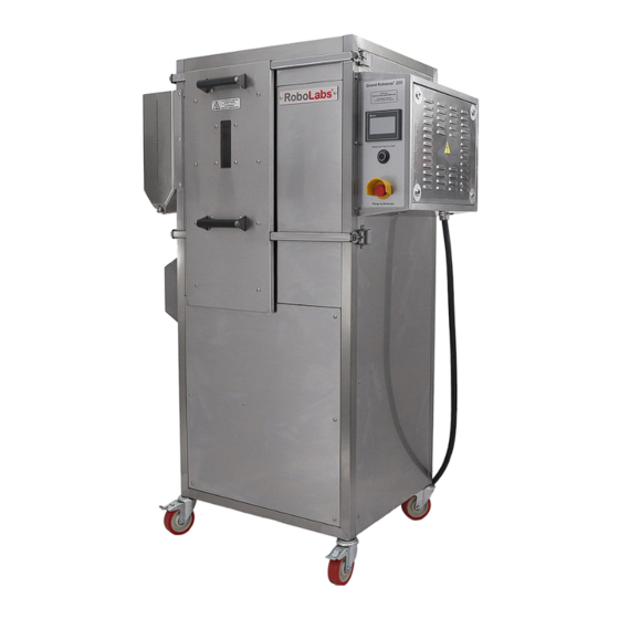
- Page 1 Popcorn machine VPM-RGM2 User manual Read this manual before use and keep for future reference! PDF version of this manual is available on www.robolabs.pro...
- Page 2 Safety requirements This is the safety alert symbol. It is used to alert you to potential physical injury hazards. Obey all safety messages that follow this symbol to avoid possible injury or death. DANGER • Not grounded equipment can cause electric shock. Power outlet MUST HAVE PROPER GROUNDING to avoid electric shock.
-
Page 3: Table Of Contents
Contents 1 General information 1.1 Technical specifications ........1.2 Manufacturer details . -
Page 4: General Information
1 General information VPM-RGM2 is a hot-air popcorn making machine (hereinafter “the machine” or “the popper”, or “the equipment”). It can process both Butterfly and Mushroom popcorn kernels. Commercial use only. 1.1 Technical specifications Throughput up to 100 kg/h Rated voltage... -
Page 5: Warranty Obligations
(in accordance with transport documentation); or, in case of purchase directly through Trapeza LLC or RoboLabs Ltd., from the date of purchase, given that terms of using, transportation, and storage are met. -
Page 6: Assembling And Installation
2 Assembling and installation 2.1 Delivery set Popcorn machine Electric panel key Cleaning brush Spare halogen lamp Documentation set 2.2 Assembling 1. Unpack the machine carefully. 2. Check the delivery set. 3. Remove protective film from all surfaces. 4. Wipe all surfaces with a clean soft cloth dampen with mild soap. Then remove soap residues with a clean cloth dampen with water. -
Page 7: Design And Principle Of Operation
3 Design and principle of operation 3.1 Main components Figure 1: Main components Main components of machine is represented on Fig. 1. Motor with turbine causes air circulation inside the machine. Air goes from the turbine to the working chamber, then to the heating elements area, where it is heated, and finally goes back to the turbine. -
Page 8: Controls
From the corn bin, corn kernels goes to working chamber, through the corn supply tube, see Fig. 3. Perforated bowl has many holes of spe- cial shape, which cause air vortex inside the chamber as airflow goes through the bowl. Due to air vortex, corn kernels are constantly moving inside the chamber around center of the bowl. -
Page 9: Stages Of Operation
3.3 Stages of operation Whenever the machine is turned on, it is in one of the following stages of operation. Standby mode Once the machine is turned on, the HMI panel boots up, and the machine is waiting for operator action. -
Page 10: Intended Use
4 Intended use DANGER • DO NOT USE if power cord, or plug, or wall outlet are damaged, and also if chamber lamp is blown out. WARNING • DO NOT USE emergency stop switch for routine stop. Doing so might lead to machine failure and smoke formation. - Page 11 5. Press to start heating up. The display reads HEATING: v 1.1 6. Once warmed up, the machine begins to execute production cycle. Each stage of the cycle is represented as ’FEEDING’ , ’POPPING’ and ’PURGE’ . 7. To suspend the operation, press .
-
Page 12: Chamber Clogging
4.2 Chamber clogging DANGER • NEVER USE WATER in case of smoke formation. WARNING • DO NOT OPEN in case of smoke formation. • DO NOT USE fire extinguishers. Machine is made of stainless steel, as long as chamber is closed, popcorn won’t get fire. The chamber may be clogged due to the following reasons: •... -
Page 13: Hmi Interface
5 HMI interface The HMI interface consists a range of screens (see Fig. 5), that provide ability of controlling and monitoring of machine operation, changing parameters of operation and settings of the machine, and also testing of the machine. MIN: 190.0 MAX: 250.0 210.0 ATTENTION! -
Page 14: Initial Screen
5.1 Initial screen The initial screen (Fig. 6) appears first after machine turned on. Figure 6: Initial screen Figure 7: Error messages v1.1 – version of software. 154.2 PV – current temperature in the chamber. – press to start popping process. v 1.1 –... -
Page 15: Testing Screen
5.2 Testing screen Figure 8: Testing screen Operation time 14.2 – Total operation time in hours. LOW CORN – Corn bin sensor indicator. Yellow when tripped. CLOGGING – Chamber optical sensor indicator. Yellow when tripped. DEFAULT – Reset all settings to default (password required, see below). –... -
Page 16: Settings Screen
5.3 Settings screen Figure 9: Settings screen Corn auger rpm/time – Speed of corn auger and duration of feeding cycle, in seconds. Popping time – duration of popping stage, in seconds. add.popping freq. – increment for turbine speed during popping stage, in Hz. freq.increase start/step –... -
Page 17: Operation Process Screens
5.4 Operation process screens LOW CORN – error message (if error condition presents). the following options are possible: • LOW CORN – Photoelectric sensor in the corn hopper is tripped. Refill the hopper. • VFD ERROR – Turbine drive (VFD) has an error. •... -
Page 18: Process Monitoring Screen
Figure 13: Process monitoring screen 5.5 Process monitoring screen 210.0 – working temperature set value. Press to change the value. 203.5 PV – current temperature in the chamber. 27.50 – set value for basic turbine speed. Press to change the value. 27.50 PV –... -
Page 19: Temperature Graph Screen
5.6 Temperature graph screen Figure 14: Temperature graph screen 11:33 – Current time. 201.5 – Temperature value at the point where the vertical dashed line intersects the temper- ature graph. Touch the line and drag left or right to move across the graph. DT:30.0 –... -
Page 20: Maintenance And Cleaning
6 Maintenance and cleaning DANGER • DO NOT USE EXCESSIVE WATER OR WATERJET for cleaning. • DO NOT SPILL WATER on the machine. • ALWAYS KEEP power cord plug off the floor and water. WARNING • Inner and outer surfaces of the chamber, as well as corn supply tube are very hot.
Need help?
Do you have a question about the VPM-RGM2 and is the answer not in the manual?
Questions and answers