
Related Manuals for RoboLabs Vortex Popcorn Robopop 60


Summary of Contents for RoboLabs Vortex Popcorn Robopop 60
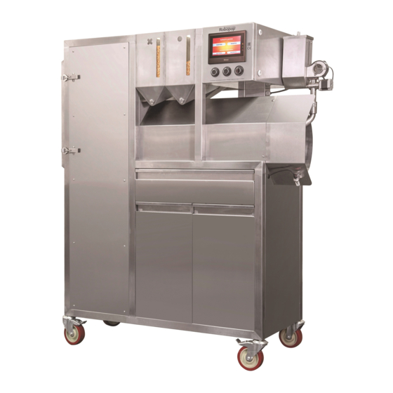
- Page 1 Vortex popcorn machine Robopop 60 (VPM-RM4) Technical service manual Read this manual before use and keep for future reference! PDF version of this manual is available on www.robolabs.pro...
- Page 2 Safety requirements This is the safety alert symbol. It is used to alert you to potential physical injury haz- ards. Obey all safety messages that follow this symbol to avoid possible injury or death. DANGER • THIS MANUAL IS FOR SKILLED TECHNICIANS ONLY! •...
-
Page 3: Table Of Contents
Contents 1 Backlight 2 VFD (inverter) 3 Fiber amplifier 4 Voltage control relay 5 Temperature limiter 6 Chamber deep cleaning 7 Heating circuit 7.1 Heating elements check ........7.2 Solid-state relays check . -
Page 4: Backlight
1 Backlight DANGER • Electric shock hazard! Unplug the machine before servicing. WARNING • Burn hazard! Wait until machine is cooled down. 1. Unplug the machine. Wait until it cools down. 2. Open the chamber. Locate the backlight (Fig.1). 3. Remove two screws that holds protective screen (1); take the screen o . -
Page 5: Vfd (Inverter)
2 VFD (inverter) DANGER • Electric shock hazard! High voltage inside electric panel. DO NOT touch bare terminals and/or wires. NOTE 1: VFD setup must be performed only when the drive is stopped. NOTE 2: After setting parameter 02.00 to 9, VFD displays End , and gets back to the main indication mode. -
Page 6: Fiber Amplifier
3 Fiber amplifier DANGER • Electric shock hazard! High voltage inside electric panel. DO NOT touch bare terminals and/or wires. Figure 3: Paper screen Figure 4: Fiber amplifier 1. Put a folded sheet of white paper in the chamber as shown on Fig.3, so the light ray of the sensor is screened. -
Page 7: Voltage Control Relay
4 Voltage control relay DANGER • Electric shock hazard! High voltage inside electric panel. DO NOT touch bare terminals and/or wires. Voltage control relay (Fig.5) is intended to protect the ma- chine from improper connection and from voltage devia- tions in the service grid. Set-up procedure 1. -
Page 8: Temperature Limiter
5 Temperature limiter DANGER • Electric shock hazard! High voltage inside electric panel. DO NOT touch bare terminals and/or wires. TC4SP unit (Fig.6) has three setting groups: 1st setting group, 2nd setting group, and SV setting group (the main indication mode). The settings must be changed in the same order as they appear in the list. -
Page 9: Chamber Deep Cleaning
6 Chamber deep cleaning Over time, corn dust and husk might be accumulated in hidden areas of the chamber. This negatively a ects normal airflow in the corn supply tube. If corn supply tube clogged with popcorn frequently, then it is necessary to clean those areas of the chamber. Chamber section view Figure 7: Chamber deep cleaning 1. -
Page 10: Heating Circuit
7 Heating circuit Figure 8: Elements of heating circuit 7.1 Heating elements check 1. Unplug the machine and see Fig.8. 2. Measure the resistance between T1 and T2; it must be 20-22 Ohms. (a) If it reads OL, then check heaters wiring, busbars, and the heaters directly. (b) If it reads 30-31 Ohms, then one of the heating elements is fault, see the next steps. -
Page 11: Solid-State Relays Check
7.2 Solid-state relays check 1. Turn the machine on. 2. Make sure LED indicators are o . 3. Check to see if the mains voltage (208 Vac) presents at L1. (a) If negative, perform Contactor check, see below. (b) If Contactor check positive, then disconnect the machine and check the consistency be- tween L1 and 1. -
Page 12: Temperature Limiter Output Check
(a) If no mains voltage presents at 2, 4, 6 then unplug the machine, open the plastic hatch covering armature plunger Y; use a suitable tool to press the plunger inside the contactor. While pressed terminals 1,3,5 must be closed to 2,4,6, respectively. If the plunger cannot be moved inside smoothly, or doesn’t close the terminals, the contactor must be replaced.
Need help?
Do you have a question about the Vortex Popcorn Robopop 60 and is the answer not in the manual?
Questions and answers