
Related Manuals for RoboLabs Robopop 75


Summary of Contents for RoboLabs Robopop 75
- Page 1 Vortex popcorn machine Robopop 75 (VPM-RM4LT) (VPM-RM4LTUS) User manual Read this manual carefully before use and keep for future reference! PDF version of this manual is available on www.robolabs.pro...
- Page 2 Safety requirements DO NOT use excessive water while cleaning! DO NOT disassemble the machine while it is con- nected to the mains! Some parts might be hot while in operation! DO NOT process other kernels than corn! Only instructed personnel is allowed to operate the equipment! DO NOT not leave running machine unattended! Read and understand all instructions before use!
-
Page 3: Table Of Contents
Contents 1 Overview 1.1 Purpose ......1.2 Technical specifications ....1.3 Delivery set . - Page 4 6.5 Sifter rollers cleaning ..... . 6.6 Feeder cleaning ......6.7 Conservation .
-
Page 5: Overview
Overview Purpose Vortex Popcorn™ machine Robopop 75 is a hot-air popcorn making ma- chine (hereinafter "machine"). It can process both Butterfly and Mush- room popcorn varieties. Machine is based on patented Vortex technology that has following advantages: • No oil is used at all. As a result, popcorn has no carcinogens and trans-fats;... -
Page 6: Assembling And Installation
Assembling and Installation Unpack the machine carefully. Check the delivery set. Remove protective film from all surfaces. Put at the dedicated place, lock all four swivel casters. Power requirements Power outlet must have grounding contact! Presence of grounding connection must be checked on regular basis! If supply cord damaged, it must be replaced by manufacturer, service agent, or qualified persons... -
Page 7: Design And Operating Principle
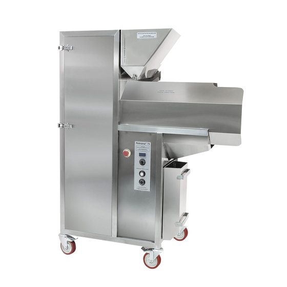
Main components of the machine are: 1 – Turbine; 2 – Chamber; 3 – Hopper with feeder; 4 – Sifter (perforated drum); 5 – Popcorn cart with plastic bag; 6 – Scrap tray; 7 – Control panel, see Figure 1. Figure 1: Robopop 75 main components... -
Page 8: Turbine (Blower)
Turbine (blower) The turbine provides constantly circulating airflow inside the machine. This is a direct type drive; the blower sits on motor’s shaft. Rotational speed is controlled by the main controller of the machine. Chamber This is where popping happens. Airflow circulates through the chamber; air is being heated by heating elements. -
Page 9: Hopper
Hopper Corn hopper can fit one standard bag of corn (22,68 kg / 50 Lbs). Equipped with feeding auger. Control panel 1. EMERGENCY STOP push button. 2. 4-digit LED display. Shows parameter values, alerts and notifications. 3. TEMPERATURE adjusting buttons, marked with up and down arrows. -
Page 10: Intended Use
Intended use Modes of operation During operation, the machine is operated in different modes: Heating mode Once machine is turned on, it automatically starts to heat up. Upon reaching certain temperature machine switches automatically to popping mode. Popping mode This is the main operating mode. Machine operates in cyclic way, process- ing corn kernels batch by batch. -
Page 11: Operating Parameters
Setup mode This mode is used for fine adjustment of the machine and also to test feeder and sifter. For more details see Technical manual section. Operating parameters Properly chosen parameters are essential for good quality product and stable operation process. Popping temperature and basic turbine speed are the parameters available for an operator. -
Page 12: Quick Start Instructions
Quick start instructions 1. Empty the scrap tray. 2. Fill the hopper with corn kernels. 3. Put empty plastic bag into popcorn cart and put the cart under the sifter. 4. Press the START/PAUSE push button to turn the machine on. 5. -
Page 13: Display Notifications
Display notifications Popper has 4-digit 7-segment LED indicator located on the front panel. During the operation, the following messages may appear: Reading Meaning Action required Machine is in heating mode None HHHH Machine is in cooling mode None CCCC POPP (glows) Machine is in popping mode None POPP (blinks) -
Page 14: Popcorn Quality
Popcorn quality Popcorn is a product that requires ultimate attention towards many as- pects. Understanding popcorn processing technology is essential to get high quality product. Raw corn It is impossible to get good stable result using low quality supplies, first of all, raw corn kernels. -
Page 15: Maintenance And Cleaning
Maintenance and cleaning DO NOT use excessive water while cleaning! ALWAYS unplug the machine from the mains before cleaning! DO NOT use sharp tools or abrasives! Wait until machine is cool before cleaning! The purpose of maintenance and cleaning is to keep machine in good condi- tion during all the lifetime and to meet safety requirements. -
Page 16: Clogged Chamber
dust is accumulated in the chamber. It is important to clean mesh screen. Use a soft brush or a vacuum cleaner to remove dust from the mesh screen. In case of severe clogged mesh screen do the following. 1. Open the chamber. 2. -
Page 17: Sifter Cleaning
6. Use the tube cleaning brush from the delivery set to clean the corn supply tube. Sifter cleaning Take out the sifter drum. Wash it with suitable mild detergents, wipe dry immediately. Sifter rollers cleaning During operation, the sifter rollers might accumulate corn dust and oil, be- coming greasy and slippery, affecting normal sifter operation. -
Page 18: Troubleshooting
Troubleshooting Too much scrap Possible reasons Solution Low quality corn Use high quality corn Too high turbine speed Decrease turbine speed Popcorn is not crispy Possible reasons Solution Low quality corn Use high quality corn Extreme ambient conditions Provide proper ambient conditions No exhausting hood Provide exhausting hood Popcorn is still hot... -
Page 19: Technical Manual
Technical manual This section is for qualified technical personnel only! Sifter and feeder testing Turn the machine off. Press and hold COOLING button and press START/PAUSE button once; release COOLING button as you see St-S on the display. Sifter testing Press and hold COOLING push button. The display will show St-S message and sifter starts to rotate as long as the button is kept pressed. - Page 20 tP (Time_Popping) Maximal duration of popping stage. Fr (Feeder_RPM) Corn auger speed (in rpm). The higher the value, the more corn supplied per batch. tF (Time_Feeder) Duration of auger operation (in seconds). The higher the value the more corn supplied per batch. tb (Time_Boost) Duration of purging stage (in seconds).
- Page 21 dEF (reset to default) List parameters until you see dEF on the dis- play, press and hold COOLING button and press START button once. All parameters, except basic turbine speed will be reset to its default values, and the machine will be shut off. NOTE: only available if the turbine is not running.
-
Page 22: Light Bulb Replacement
Light bulb replacement 1. Turn off the machine and disconnect it from the mains. Wait until the machine cools down. 2. Open the chamber. 3. Lamp is located on the left sidewall of the chamber. 4. Remove two screws that holds lamp screen (1) and take the screen off. -
Page 23: Vfd Unit
VFD unit Basic speed F 1. Open electric box and locate the VFD control panel: 2. Turn the machine on. 3. Use ‘up’ and ‘down’ arrow keys on VFD control panel to set the desired value. New figure will be shown on the display in real time, in format "FXX.X". - Page 24 VFD unit setup Run the machine in setup mode (the drive must be stopped). To change or view parameter value, press ENTER, the display shows 00.__ Then use up or down keys to choose the first two digits of the parameter (for example, 02.).
-
Page 25: Temperature Limiter Setup
Temperature limiter setup Temperature limiter have three setting groups: first setting group, second setting group, and SV setting group (the main indication mode). The set- tings must be changed in the same order as they appear in the list. Note that after changing In-t (temperature sensor type) or UnI-t (temperature unit) values, parameters H-Su, L-Su, AL1, AL2, AHYS must be set again. -
Page 26: Optical Amplifier Setup
Optical amplifier setup 1. Operation indicator 2. Incident level scale 3. Adjustment knob (8-turn) 4. Timer switch (must be in OFF position) 5. Mode switch (must be in L position) To adjust the optical amplifier, put a folded sheet of white paper in the chamber as shown on the picture below, so the sight line of the sensor is interrupted with this paper screen. -
Page 27: Electric Box Layout
Electric box layout VPM-RM4LT machine (3N 230/400V 50 Hz) 1 – BL optical amplifier 11 – KM1 contactor 2 – DC4 temperature limiter 12 – KM2 contactor 3 – K1, K2 relays 13 – VS1, VS2 solid-state relays 4 – DC2 temperature controller 14 –... - Page 28 VPM-RM4LTUS machine (3P 208–240 V 60 Hz) 1 – BL optical amplifier 11 – KM1 contactor 2 – DC4 temperature limiter 12 – KM2 contactor 3 – K1, K2 relays 13 – VS1, VS2 solid-state relays 4 – DC2 temperature controller 14 –...
-
Page 29: Transportation And Storage
Transportation and storage The equipment may be transported by any kind of covered vehicle, in accordance with transportation rules for this kind of vehicle. Ambient temperature during the transportation and storage must be between mi- nus 25 C and +55 C (minus 13 F and +131 F). Quality control check ——————————————–... -
Page 30: Warranty Obligations
12 months from the date of receiving the equipment by a dealer (in accordance with transport documentation); or, in case of purchase directly through RoboLabs LLC, from the date of purchase, given that terms of using, transportation, and storage are met.
Need help?
Do you have a question about the Robopop 75 and is the answer not in the manual?
Questions and answers