
Related Manuals for WAGO 2789-9023


Summary of Contents for WAGO 2789-9023
- Page 1 Communication Modules EtherNet/IP Communication Module 2789-9023 Product manual | Version 1.0.0...
- Page 2 We wish to point out that the software and hardware terms as well as the trademarks of companies used and/or mentioned in the present manual are generally protected by trademark or patent. WAGO is a registered trademark of WAGO Verwaltungsgesellschaft mbH. Product manual | Version: 1.0.0 EtherNet/IP Communication Module...
-
Page 3: Table Of Contents
2789-9023 Table of Contents Table of Contents Provisions ........................ 6 Intended Use ...................... 6 Typographical Conventions .................. 7 Legal Information ..................... 9 Safety .......................... 10 General Safety Rules .................... 10 Electrical Safety ..................... 10 Mechanical Safety .................... 10 Thermal Safety ...................... 11 Indirect Safety...................... - Page 4 Device Parameter Object ................ 31 4.2.7 4.2.7.1 General Device Parameters of Lower-Level Devices...... 31 4.2.7.2 Device Parameters of the WAGO Pro 2 Power Supply....... 33 4.2.7.3 General Services................. 35 Module Parameter Object ................ 36 4.2.8 Measurement Data Object ................ 38 4.2.9...
- Page 5 2789-9023 Table of Contents Exporting WBM Certificates................ 80 11.1.5 Exporting MQTT Certificates ................ 82 11.1.6 Installing WBM Certificates on the Client and Product ......... 85 11.1.7 Installing MQTT Certificates on the Broker and Product ...... 86 11.1.8 11.2 Accessories ...................... 87 11.3 Protected Rights ....................
-
Page 6: Provisions
The terms set forth in the General Business and Contract Conditions for Delivery and Service of WAGO GmbH & Co. KG and the terms for software products and products with integrated software stated in the WAGO Software License Contract – both available at ü www.wago.com... -
Page 7: Typographical Conventions
2789-9023 Provisions • The deficiency (hardware and software configurations) is due to special instructions. • Modifications to the hardware or software have been made by the user or third parties that are not described in this documentation and that has contributed to the fault. - Page 8 Provisions 2789-9023 ð This symbol identifies the result of an action. • Individual action step Lists • Lists, first level – Lists, second level Figures Figures in this documentation are for better understanding and may differ from the actual product design.
-
Page 9: Legal Information
1.3 Legal Information Intellectual property The intellectual property of this document belongs to WAGO GmbH & Co. KG. The repro- duction and distribution of its content (in whole or in part) is prohibited, unless otherwise provided by statutory provisions, written agreements or this document. In case of doubt, the written consent of WAGO GmbH &... -
Page 10: Safety
Safety 2789-9023 Safety 2.1 General Safety Rules • This documentation is part of the product. Therefore, retain the documentation during the entire service life of the product. Pass on the documentation to any subsequent user of the product. In addition, ensure that any supplement to this documentation is included, if necessary. -
Page 11: Thermal Safety
• Clean tools and materials are imperative for handling the product. • The product contains no parts that can be serviced by the user. Always have all ser- vice, maintenance and repair work performed by specialists authorized by WAGO. • Replace any defective or damaged devices. -
Page 12: Properties
Properties 3.1 Overview This product supports ETHERNET-based communication with a lower-level device (such as a WAGO Power Supply Pro 2 with firmware version 01.04.xx or higher). It functions as a gateway. The following protocols are supported: • EtherNet/IP (Industrial Protocol) •... -
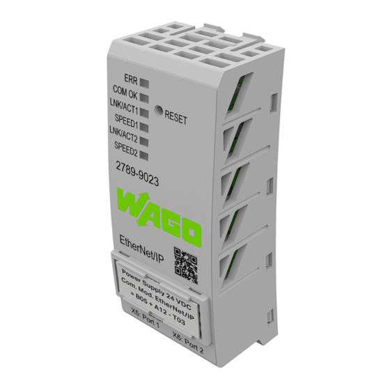
Page 13: Type Label
2789-9023 Properties 3.3 Type label The product’s type plate contains the following information: Position Comment Details Company logo and address – Item number – Product name – Warning notice symbols 8 Safety [} 10] QR link with link to website – Reference to product documentation –... -
Page 14: Product-Specific Information
2D data matrix code Contains the information for positions 2 … 5 Key number Fixed information (37S) ID number per D-U-N-S® Fixed information (WAGO Minden) WAGO item number or internal SAP number Product-specific Consecutive number Product-specific Production date and revision • Production date •... -
Page 15: Connections
2789-9023 Properties 3.5 Connections 3.5.1 RJ-45 Interfaces The connection to ETHERNET-based fieldbuses is established via two RJ45 connectors (see figure “RJ45 Interface, X5/X6”), also called “Western plugs,” which are connected to the fieldbus controller via an integrated switch. The integrated switch works in store-and-forward mode and supports 10/100 Mbit/s trans- mission speeds, as well as full and half-duplex transmission modes, for each port. -
Page 16: Indicators
Properties 2789-9023 3.6 Indicators The product has a visual status indicator. This indicator consists of six LEDs. COM OK LNK/ACT1 SPEED1 LNK/ACT2 SPEED2 Figure 4: Visual Status Indicator Table 2: Operating Status Indication Indicator LED Description State Description Error Ready for operation; no error General error/system error Flashing (8 Hz) -
Page 17: Power Loss
Protection type IP20 When the EtherNet/IP™ communication module is used in combination with a WAGO Power Supply Pro 2 ap- proved for a maximum ambient temperature of +70 °C, a maximum ambient temperature of +55 °C must not be exceeded during operation. -
Page 18: Approvals
Properties 2789-9023 3.9.2 Approvals The following approvals have been granted for the product: Table 7: Approvals Logo Certification Body Standard Underwriters Laboratories Inc. UL 61010-1 (Ordinary Locations) Underwriters Laboratories Inc. UL 61010-2-201 (Ordinary Locations) Underwriters Laboratories Inc. UL 121201 (Hazardous Locations) -
Page 19: Standards
2789-9023 Properties 3.9.3 Standards Table 8: Mechanical and Climatic Environmental Conditions Standard Test Value Mechanical Environmental Conditions EN 60068-2-6 f = 5 …150 Hz: 1g, 3.5 m IEC 60068-2-27, Shock 15g, 11 ms, 6 shocks per axis and direction, half-sine EN 61131-2, Section 4.3 Freefall ≤ 300 mm (packaged in the product packaging) -
Page 20: Fieldbus Description
EDS file for the configuration software you are using. Note Downloading the EDS file You can download the EDS file from the download area of the WAGO website: ü www.wago.com/2789-9023. Product manual | Version: 1.0.0... -
Page 21: Overview Of The Objects
2789-9023 Fieldbus Description 4.2 Overview of the Objects The CIP objects are specified in the CIP specification of ODVA. WAGO uses classes 0x01, 0x04, 0x05, 0xF4, 0xF5 and 0xF6. In addition, three specific WAGO objects are available. All listed CIP common objects and WAGO-specific objects are described below. -
Page 22: Identity Object
Fieldbus Description 2789-9023 Data type Description STRUCT of: Combines multiple parameters into one structure Electronic Key Segment 4.2.1 Identity Object The Identity object (Class 0x01) provides general information about the product that can be used to clearly identify it. 4.2.1.1 Instances Table 15: Identity Object –... - Page 23 2789-9023 Fieldbus Description Attribute Access Name Data type Description Factory setting Product Name CHAR[ ] Product name WAGO Communication Module Product manual | Version: 1.0.0 EtherNet/IP Communication Module...
-
Page 24: General Services
For example, these might include input and output data, status and control information or diagnostic information. WAGO uses the manufacturer-specific instances to provide these objects for you in various ar- rangements. -
Page 25: Instances
2789-9023 Fieldbus Description 4.2.2.1 Instances Assembly instance 101 (attribute ID 3) contains the process input data. Table 18: Assembly Object – Instance 101, Attribute ID 3 Access Name Data type Description EtherNet/IP module UINT16 Bit 0 Communication with lower- status level device OK Bits 1 …... -
Page 26: General Services
Fieldbus Description 2789-9023 4.2.2.2 General Services This object supports the following common services. Table 20: Common Services Service Code Service Available Service Name Description Class Instance 0x0E Get_Attribute_All Returns the content of all attributes 0x10 Get_Attribute_Single Returns the content of the respec- tive attribute 4.2.3 Connection Object... -
Page 27: Table 22: Tcp/Ip Interface Object - Instance 1
2789-9023 Fieldbus Description Attribute Access Name Data type Description Factory setting Number of In- UINT16 Number of connections currently stances instantiated Table 22: TCP/IP Interface Object – Instance 1 Attribute Access Name Data type Description Factory setting Status UINT32 Interface status... -
Page 28: General Services
Fieldbus Description 2789-9023 4.2.5.2 General Services This object supports the following common services. Note Changes made via “Set_Attribute_Single” do not take effect immediately! Attributes that you change via the “Set_Attribute_Single” service do not take effect until the next time the product is restarted. -
Page 29: Table 25 Ethernet Link Object - Instance 1 (Port 1)
2789-9023 Fieldbus Description Table 25: Ethernet Link Object – Instance 1 (Port 1) Attribute Name Data type Description Factory set- cess ting Interface UINT32 Transmission rate 0x0000000A Speed 0x00000064 Interface UINT32 Interface configuration/status information Dependent Flags on ETHER- Bit 0 Link Status... -
Page 30: Table 26 Ethernet Link Object - Instance 2 (Port 2)
Fieldbus Description 2789-9023 Table 26: Ethernet Link Object – Instance 2 (Port 2) Attribute Name Data Description Factory set- cess type ting Interface UINT32 Transmission rate 0x0000000A Speed 0x00000064 Interface UINT32 Interface configuration/status information Dependent Flags on ETHER- Bit 0 Link Status... -
Page 31: General Services
2789-9023 Fieldbus Description 4.2.6.2 General Services This object supports the following common services. Note Changes made via “Set_Attribute_Single” do not take effect immediately! Attributes that you change via the “Set_Attribute_Single” service do not take effect until the next time the product is restarted. -
Page 32: Table 29 General Device Parameters - "Password Level" Parameter
Fieldbus Description 2789-9023 „Password“ Parameter Note The device must be locked manually! After the lower-level device is unlocked, it is not automatically relocked. The device lock must be performed manually. The parameter is used in big-endian format. Only ASCII characters may be used (e.g., for password “123,”... -
Page 33: Device Parameters Of The Wago Pro 2 Power Supply
Middle-endian (B2, B3, B0, Little-endian (B3, B2, B1, 4.2.7.2 Device Parameters of the WAGO Pro 2 Power Supply The following parameters of the WAGO Pro 2 Power Supply can be edited via the prod- uct. Product manual | Version: 1.0.0... -
Page 34: Table 31 Parameters - Dc Output
Fieldbus Description 2789-9023 DC Output Table 31: Parameters – DC Output Attribute ID Access Data type Description Get/Set UINT16 Output voltage (unit: mV) Get/Set UINT16 Warning threshold (unit: mA) Get/Set UINT16 Bit 0 Switch output on Bit 1 “Active droop” parallel switching mode... -
Page 35: General Services
2789-9023 Fieldbus Description Attribute ID Access Data type Description Bit 4 Activation of the readout function of the digital output via the process data Bit 5 Switching digital output on and off Bits 6 … 9 Reserved Bit 10 Inversion Bits 11 …... -
Page 36: Module Parameter Object
Fieldbus Description 2789-9023 4.2.8 Module Parameter Object The Module Parameter object (Class 0x78) provides access to the internal module pa- rameters and module information. Only instance ID 1 is implemented for this object. Cross-Device Information for Identification Table 37: Internal Module Parameters – Cross-Device Information for Identification... -
Page 37: Table 39 Internal Module Parameters - Switch Settings For Channel
2789-9023 Fieldbus Description Attribute Access Data type Description Value Limits Factory setting Min. Max. Get/Set UINT16 Enables BroadcastStormProtection (0 = off, 1 = on) Switch Settings for Channel 2 Table 40: Internal Module Parameters – Switch Settings for Channel 2 Attribute... -
Page 38: Measurement Data Object
Only instance ID 1 is implemented for this object. 4.2.9.1 Events and Measured Values The object outputs the WAGO-specific events and measured values listed below. Process Output Data Table 44: Events and Measured Values – Process Input Data... -
Page 39: Table 45 Events And Measured Values - Status Messages
2789-9023 Fieldbus Description Status Messages Table 45: Events and Measured Values – Status Messages Attribute ID Access Data type Description UINT16 Bit 0 DC status OK Bit 1 Overtemperature Bit 2 No output voltage Bit 3 Short circuit at output Bit 4... -
Page 40: General Services
Fieldbus Description 2789-9023 Power/Energy Table 48: Events and Measured Values – Power/Energy Attribute ID Access Data type Description UINT32 Output power (unit: W) UINT32 Output level of previous second (unit: Ws) UINT32 Output level of previous minute (unit: Ws) UINT32 Output level of previous hour (unit: Wh) 4.2.9.2 General Services... -
Page 41: Mqtt
2789-9023 Fieldbus Description 4.3 MQTT “Message Queuing Telemetry Transport” (MQTT) defines an open network protocol that is the preferred choice for exchanging data between IoT (“Internet of Things”) devices. The product is an MQTT client that can be connected to a local broker. -
Page 42: Table 52 Writing Process Data In Json Format
"Output" : { "Device standby" : "value" "Digital out on" : "value" } 1 Not yet supported by the WAGO Pro 2 Power Supply The following process data can be written in JSON format (communication module “Sub- scribe” from the broker): Table 52: Writing Process Data in JSON Format... -
Page 43: Table 53 Reading Out Process Data In Binary Format
Bit 0 Device standby Bit 1 Digital output on 1 Not yet supported by the WAGO Pro 2 Power Supply The following process data can be written in binary format: Table 54: Writing Process Data in Binary Format Byte Data type... -
Page 44: Application Examples
Figure 5: Raspberry Pi as MQTT Broker • The product serves as an MQTT client. • A WAGO PFC200 (e.g., item no. 750-8212) serves as an MQTT client for integrating the communication modules into CODESYS or e!COCKPIT. • Any computer (e.g., a Raspberry Pi with a Mosquitto MQTT broker) can serve as the MQTT broker. -
Page 45: Transport And Storage
2789-9023 Transport and Storage Transport and Storage The original packaging offers optimal protection during transport and storage. • Store the product in suitable packaging, preferably the original packaging. • Only transport the product in suitable containers/packaging. • Make sure the product contacts are not contaminated or damaged during packing or unpacking. -
Page 46: Installation And Removal
Mounting Figure 7: Mounting Install the product by snapping it onto the WAGO Power Supply Pro 2 (see figure “Instal- lation”): 1. Remove the cap from the communication interface on the WAGO Power Supply Pro 2. Keep the cap in a safe place so that you can cover the communication interface again when this interface is not required. - Page 47 Only remove the product when it is switched off. Figure 8: Removal 1. Press the top locking tab (a) of the product [C]. 2. Pivot the product to remove it from the WAGO Power Supply Pro 2 [D]. NOTICE Avoid electrostatic discharge! The products are equipped with electronic components that you may destroy by electro- static discharge when you touch.
-
Page 48: Commissioning
Commissioning 2789-9023 Commissioning 7.1 Setting an IP address 7.1.1 Assigning an IP Address Using DHCP ü Snap the product onto a lower-level device. ü Connect the product to a computer via a network cable and integrate it into a network. -
Page 49: Setting A Static Ip Address
2789-9023 Commissioning 7.1.2 Setting a Static IP Address To use the IP address permanently, you can switch the addressing to “static.” The follow- ing options are available for this: • Setting the IP address via the WBM • Setting the default IP address with the reset button •... - Page 50 Commissioning 2789-9023 Figure 10: Module Settings > System Setting the Default IP Address with the Reset Button Note If you no longer have the IP address of the module, you can reset the network settings with the reset button on the module.
-
Page 51: Operation
2789-9023 Operation Operation 8.1 Operating via Reset Button The reset button can be used to reset the product. The following settings options are available: Table 55: Using the Reset Button Settings Options Description Signaling via Visual Status Display Hold reset button down for eight... -
Page 52: Configuration
Configuration 2789-9023 Configuration 9.1 Configuring with WBM Using the Web-Based Management (WBM), you can view parameters and measured val- ues of the communication module and the lower-level device and make changes via a Web browser. 9.1.1 Logging In If the lower-level device is password-protected, one of the following messages appears, depending on the password level: Figure 11: Login with Read/Write Protection... -
Page 53: Module Settings
2789-9023 Configuration Figure 13: Menu Page On the menu page, you will see tiles offering the following entry points: • Module Settings • Module Information • Device Settings • Device Information • Device Measurements 9.1.3 Module Settings System Figure 14: Module Settings > System Date / Time: Here you can set the module’s date and time. - Page 54 Configuration 2789-9023 Firmware Update: You can also update the module’s firmware. Clicking the [Start] but- ton takes you out of the application and launches the internal firmware loader. Note Please note the version of the firmware loader! Below, examplary images of a particular version are used. Therefore, note that your WBM interface differs depending on the version you're using.
- Page 55 2789-9023 Configuration MQTT 8 MQTT You can change the MQTT settings here; see [} 41]. Figure 15: Module Settings > MQTT • ID: client ID used for connecting to the broker; can only be used once if multiple clients are used • User/Password: If the broker requires authentication with a username and password, these can be configured here •...
- Page 56 Configuration 2789-9023 • Encapsulation Inactivity Timeout: time interval for closing an inactive connection Network Figure 17: Module Settings > Network Note Restart after modifying the network settings! After settings are modified on this page, the product must be restarted with [Reboot Module] or by power cycling it.
- Page 57 2789-9023 Configuration Figure 18: Module Settings > Parameter Management • Parameter Export: module and device parameter settings can be exported • Parameter Import: module and device parameters can be imported Switch Settings Figure 19: Module Settings > Switch settings • Enable Autonegotiation: Autonegotiation allows the UTP (Unshielded Twisted Pair) link partners to select the best common operating mode in accordance with Clause 28 of the IEEE 802.3u specification.
- Page 58 Configuration 2789-9023 Figure 20: Module Information > General • Connection to Device: Green means the connection is established; red means the connection is disrupted. Customer Users can enter system and location information here: Figure 21: Module Information > Customer 9.1.5 Device Settings The individual menu pages of the Device Settings are shown below.
- Page 59 2789-9023 Configuration Figure 22: Device Settings > DC Output • General: Here you can make general settings concerning how DC output switches on or off, and with Output On, the current output voltage is also displayed. • Overload Behavior: Here you can specify how the product should behave in case of overload.
- Page 60 Configuration 2789-9023 Figure 23: Device Settings > Signalization • Digital Input: Here you can switch the power supply on and off and make additional settings. • Digital Output: This contains various setting options for the digital output; Digital Out- put On and Inversion are locked and cannot be selected at the same time as other settings.
- Page 61 2789-9023 Configuration System Figure 24: Device Settings > System • Power On Behavior: Here you can configure the behavior when power is applied. • User Interface: Here you can set locks for the user. • Date / Time: The date and time can be taken from the PC used.
-
Page 62: Device Measurement
Configuration 2789-9023 Modbus Figure 26: Device Settings > Modbus • General: In this area, you can set specific parameters for the communication module. See also 2 Device Parameter Object [} 31] 9.1.6 Device Information Here you can see the information on the lower-level device. -
Page 63: Configuration Of Communication With Broker
2789-9023 Configuration • Green: function or state OK • Red: function or state faulty/tripped A history of the last error and warning messages can be viewed on the Logging page: Figure 29: Device Measurement > Logging 9.1.8 Configuration of Communication with Broker The communication between the communication module and a broker can be configured 8 Mod-... - Page 64 Configuration 2789-9023 Figure 31: Application-Specific Settings 3. In the Client Settings > MQTT Connection area, select the Enable without TLS/ SSL option to connect to the broker. Figure 32: Enabling without TLS/SSL ð The current status of the connection is shown under MQTT Connection Status.
- Page 65 2789-9023 Configuration Figure 35: Application-Specific Settings 8 User Certificates 3. Create certificate (see [} 67]). 4. Update the module date/time (see 8 Module Settings [} 53]). 5. In the Broker Settings > Certificate Upload area, upload the CA file that has been created. Figure 36: Selecting the Certificate File 6.
-
Page 66: Decommissioning
Decommissioning 2789-9023 Decommissioning 10.1 Disposal and Recycling WEEE Mark Electrical and electronic equipment may not be disposed of with household waste. This also applies to products without this mark. Electrical and electronic equipment contain materials and substances that can be harmful to the environment and health. -
Page 67: Appendix
2789-9023 Appendix Appendix 11.1 User Certificates A certificate allows a secure connection for network communication and is used for au- thenticating the remote host. The lock icon in the browser indicates that this website has a valid, trusted certificate and that the connection is secure. We recommend replacing the self-signed certificates generated in the product with your own. -
Page 68: Creating And Replacing Certificates
Appendix 2789-9023 11.1.1 Creating and Replacing Certificates The following table lists the available cipher suites Table 56: Available Cipher Suites IANA No. Cipher Suite TLS1.3 0x13, 0x01 TLS_AES_128_GCM_SHA256 0x13, 0x02 TLS_AES_256_GCM_SHA384 0x13, 0x04 TLS_AES_128_CCM_SHA256 0x13, 0x05 TLS_AES_128_CCM_8_SHA256 TLS1.2 0xC0, 0xAC TLS_ECDHE_ECDSA_WITH_AES_128_CCM... - Page 69 2789-9023 Appendix Figure 40: XCA Database 4. On the Templates tab, click the [New Template] button. 5. Select the “[Default] Blank Template” setting in the Preset Template Values dialog that opens. 6. Click [OK] to confirm the selection. 7. In the Change XCA Template dialog that opens, switch to the Owner tab.
- Page 70 Appendix 2789-9023 Figure 41: Owner Tab Input Field Explanation Internal name The value in this field serves as an internal reference and should identify the cer- tificate uniquely countryName Country code (e.g., DE for Germany) stateOrProvinceName State or province (e.g., NRW for North Rhine-Westphalia)
-
Page 71: Creating The Root Ca Certificate
2789-9023 Appendix Figure 42: Creating a Template 11.1.3 Creating the Root CA Certificate 1. Switch to the Certificates tab to create the Root CA certificate. Click the [New Cer- tificate] button. ð The following dialog appears. Product manual | Version: 1.0.0... - Page 72 Appendix 2789-9023 Figure 43: Creating a Certificate – Selecting a Template 2. Select your created template from the Template for the New Certificate selection field. 3. Click the [Apply Subject] button. 4. Select the [Default] CA template from the Template for the New Certificate selec- tion field.
- Page 73 2789-9023 Appendix Figure 44: Creating a Certificate – Entering a Name 7. Enter an identifier in the CommonName input field (e.g., “Root_CA”). 8. Click the [Create a New Key] button. Product manual | Version: 1.0.0 EtherNet/IP Communication Module...
- Page 74 Appendix 2789-9023 Figure 45: Creating a New Key 9. Set the key type to “EC” and select an EC curve for the root CA. The name is preset. The assignment depends on whether the key is generated for the root CA or for the module.
-
Page 75: Creating The Device Certificate
2789-9023 Appendix Figure 46: New Certificate Created 11.1.4 Creating the Device Certificate 1. Go to the Certificates tab to create the device certificate. 2. Click the [New Certificate] button. ð The following dialog appears. Product manual | Version: 1.0.0 EtherNet/IP Communication Module... - Page 76 Appendix 2789-9023 Figure 47: Creating a New Device Certificate 3. Check the Use This Certificate for Signing box and select the root CA certificate that has been created. 4. In the Signature Algorithm selection field, select the value “SHA 512” (see the BSI TR-02102 technical guidelines).
- Page 77 2789-9023 Appendix Figure 48: Creating a New Key 12. Change the key type to elliptic curve and select the prime256v1 curve. 13. Click the [Create] button to create the key. 14. Switch to the Extensions tab. Product manual | Version: 1.0.0...
- Page 78 Appendix 2789-9023 Figure 49: “Extensions” Tab 15. Set the validity of the device certificate. Please note the recommendations of the BSI TR-02102-2 technical guidelines. 16. Add the IP address and/or host name in the X509v3 Subject Alternative Name in- put field.
- Page 79 2789-9023 Appendix Figure 50: New Certificate Request, “Client” Key Use 19. Click [OK] to confirm the entries. The new certificate is shown below the root CA certificate on the Certificates tab. Product manual | Version: 1.0.0 EtherNet/IP Communication Module...
-
Page 80: Exporting Wbm Certificates
Appendix 2789-9023 Figure 51: Device Certificate Created 11.1.5 Exporting WBM Certificates 1. In the main window, switch to the Certificates tab and expand the tree structure fully. 2. Select your root CA certificate and open the context menu by right-clicking. 3. Select Export > File. - Page 81 2789-9023 Appendix Figure 52: Exporting Root CA Certificate 1 Figure 53: Exporting Root CA Certificate 2 4. Select the storage location by clicking the [ … ] button. 5. From the Export Format selection list, select the “PEM (*.crt)” entry. Product manual | Version: 1.0.0...
-
Page 82: Exporting Mqtt Certificates
Appendix 2789-9023 6. Click [OK] to confirm. 7. Select your device certificate and right-click to open the context menu. 8. Select Export > File. Figure 54: Exporting the Device Certificate 9. Select a storage location by clicking the [ … ] button. - Page 83 2789-9023 Appendix Figure 55: Exporting Root CA Certificate 1 Figure 56: Exporting Root CA Certificate 2 4. Click the [ … ] button to select the storage location. 5. From the Export Format selection list, select the “PEM (*.crt)” item. Product manual | Version: 1.0.0...
- Page 84 Appendix 2789-9023 6. Click [OK] to confirm. 7. Select your device certificate and right-click to open the context menu. 8. Select Export > File. Figure 57: Exporting Broker Certificate 9. Select a storage location by clicking the [ … ] button.
-
Page 85: Installing Wbm Certificates On The Client And Product
2789-9023 Appendix 11.1.7 Installing WBM Certificates on the Client and Product Note New device certificate is necessary if IP address/host name changes! If the IP address or host name has changed, the certificate must be recreated for the de- vice with the correct IP address or host name (see 8 Creating the Device Certificate... -
Page 86: Installing Mqtt Certificates On The Broker And Product
Appendix 2789-9023 Figure 60: Importing the Device Certificate – Secure Connection 11.1.8 Installing MQTT Certificates on the Broker and Product Note New broker certificate is necessary if IP address/host name changes! If the IP address or host name of the broker has changed, the certificate must be recre- 8 Creating the Device Certificate... -
Page 87: Accessories
2789-9023 Appendix 11.2 Accessories The following accessories are available for the product: Accessories – Marking Table 57: Accessories – Marking Description Item Number Marker Carrier 2789-1233 Marking System 2009-0110 WMB Multi Marking System 2009-0115 2009-0115/0000-0002 Accessories – Other Table 58: Accessories – Other... - Page 88 Appendix 2789-9023 ® • BACnet is a registered trademark of the American Society of Heating, Refrigerating and Air Conditioning Engineers, Inc. (ASHRAE). ® • Bluetooth is a registered trademark of Bluetooth SIG, Inc. ® ® • CiA and CANopen are registered trademarks of CAN in AUTOMATION – Interna- tional Users and Manufacturers Group e.V.
- Page 89 Table 10 EMC – Emission of Interference ..................Table 11 Overview of CIP Common Classes..................Table 12 Overview of WAGO-Specific Classes ................Table 13 Explanation of the Table Headings in the Object Descriptions .......... Table 14 Data Types Used .......................
- Page 90 List of Tables 2789-9023 Table 37 Internal Module Parameters – Cross-Device Information for Identification......Table 38 Internal Module Parameters – General ETHERNET Settings ........... Table 39 Internal Module Parameters – Switch Settings for Channel 1 ........... Table 40 Internal Module Parameters – Switch Settings for Channel 2 ...........
- Page 91 Figure 3 RJ45 Interface, X5/X6....................Figure 4 Visual Status Indicator ....................Figure 5 Raspberry Pi as MQTT Broker ..................Figure 6 WAGO PFC 200 as MQTT Broker................Figure 7 Mounting ........................Figure 8 Removal........................Figure 9 Module Settings > Network...................
- Page 92 List of Figures 2789-9023 Figure 37 Enabling with TLS/SSL ....................Figure 38 Connection Status ......................Figure 39 Browser warning message due to self-signed certificate..........Figure 40 XCA Database ......................Figure 41 Owner Tab ........................Figure 42 Creating a Template .....................
- Page 93 2789-9023 List of Figures Product manual | Version: 1.0.0 EtherNet/IP Communication Module...
- Page 94 WAGO is a registered trademark of WAGO Verwaltungsgesellschaft mbH. Copyright – WAGO GmbH & Co. KG – All rights reserved. The content and structure of the WAGO websites, catalogs, videos and other WAGO media are subject to copyright. Distri- bution or modification of the contents of these pages and videos is prohibited. Furthermore, the content may neither be copied nor made available to third parties for commercial pur-...
Need help?
Do you have a question about the 2789-9023 and is the answer not in the manual?
Questions and answers