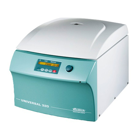
Hettich UNIVERSAL 320 Operating Instructions Manual
Hide thumbs Also See for UNIVERSAL 320:
Table of Contents

Advertisement

UNIVERSAL 320 / 320 R
Inhalt des Dokuments / content of the document
Operating instructions (EN)
Rotoren und Zubehör / Rotors and accessories
AB1401en_SA
Rev.: 04 / 11.2023

Advertisement

Table of Contents
loading
Need help?

Need help?

Do you have a question about the UNIVERSAL 320 and is the answer not in the manual?

Questions and answers

Subscribe to Our Youtube Channel

Summary of Contents for Hettich UNIVERSAL 320

  • Page 1 UNIVERSAL 320 / 320 R Inhalt des Dokuments / content of the document Operating instructions (EN) Rotoren und Zubehör / Rotors and accessories AB1401en_SA Rev.: 04 / 11.2023...
  • Page 2 Rev.: 04 / 11.2023 AB1401en_SA...
  • Page 3 Operating instructions UNIVERSAL 320 / 320 R Translation of the original operating instructions AB1401en_SA Rev.: 04 / 11.2023 1 / 44...
  • Page 4 ©2022 – All rights reserved Andreas Hettich GmbH & Co. KG Föhrenstrasse 12 D-78532 Tuttlingen, Germany Telephone: +49 (0)7461 705-0 Fax: +49 (0)7461 705-1125 Email: info@hettichlab.com, service@hettichlab.com Internet: www.hettichlab.com 2 / 44 Rev.: 04 / 11.2023 AB1401en_SA...
  • Page 5: Table Of Contents

    Table of contents Table of contents About this document........1.1 Use of this document.
  • Page 6 Table of contents 6.7 Centrifugation........6.7.1 Centrifugation in continuous operation.
  • Page 7: About This Document

    Intended use Intended use The centrifuge UNIVERSAL 320 / 320 R is an in vitro diagnostic medical device in accordance with the In Vitro Diagnostic Medical Devices Regula- tion (EU) 2017/746. The device is used for centrifugation as well as enrich- ment of sample material of human origin for subsequent further processing for diagnostic purposes.
  • Page 8: Personnel Requirements

    Any other use or use beyond this is considered improper. Andreas Hettich GmbH & Co. KG shall not be liable for any damage arising from this.
  • Page 9: Operator's Responsibility

    Safety Operator's responsibility Follow the instructions in this document for proper and safe use of the device. Keep the user manual for future reference. ■ Provide information Following the instructions in this document will help: – To avoid dangerous situations. –...
  • Page 10 Safety WARNING Dangers due to insufficient maintenance or maintenance not carried out on time. − Follow maintenance intervals. − Check the device for visible damage or defects. If any visible damage or defects are present, take the device out of service and inform a service technician. WARNING Risk of electric shock due to ingress of water or other liq- uids.
  • Page 11: Device Overview

    Do not trigger the emergency release on the device while the program is running. − Do not pull out the mains plug while the program is running. Device overview Technical data Manufacturer Andreas Hettich GmbH & Co. KG, D-78532 Tuttlingen Model UNIVERSAL 320 Type 1401 1401-01 Mains voltage (±10%) 200-240 V 1~...
  • Page 12 £68 dB(A) Noise level (rotor-dependent) Dimensions: Width 401 mm Depth 529 mm Altitude 346 mm Weight approx. 31 kg Manufacturer Andreas Hettich GmbH & Co. KG, D-78532 Tuttlingen Model UNIVERSAL 320 R Type 1406 1406-01 Mains voltage (±10%) 200-240 V 1~ 240 V 1~ 115-127 V 1~ Mains frequency 50 Hz...
  • Page 13 Device overview max. speed (RPM) 16000 max. acceleration (RCF) 24900 max. kinetic energy 9800 Nm Obligation to perform checks (DGUV Rules 100-500) (valid only in Germany) Ambient conditions (EN / IEC 61010-1): Installation site indoors only Altitude up to 2000 m above sea level Ambient temperature 5 °C to 35 °C Humidity...
  • Page 14: European Registration

    Device overview Rating plate Fig. 1: Rating plate Item number Serial number Revision Equipment number Data matrix code any labelling indicating whether medical device or in vitro diagnostic medical device Global Trade Item Number (GTIN) Date of manufacture Serial number 10 any EAC mark, CE mark 11 Country of manufacture 12 Date of manufacture...
  • Page 15: Important Labels On The Packaging

    Device overview Basic-UDI-DI Basic-UDI-DI Device assignment 040506740100139R UNIVERSAL 320 / 320 R (in vitro diag- nostic medical device) Important labels on the packaging This is the correct upright position of the shipping container for transport and/or storage. FRAGILE GOODS The contents of the shipping container are fragile, so it must be handled with care.
  • Page 16: Operating And Indicator Elements

    Device overview Attention, general danger area. Ensure you read the instructions for commissioning and operation and observe the safety instruc- tions before using the device. Biohazard warning. Direction of rotation of the rotor. The orientation of the arrow indicates the rotor's direction of rotation. Symbol for the separate collection of electrical and electronic equipment, in accordance with Directive 2012/19/EU (WEEE).
  • Page 17: Indicator Elements

    Device overview 3.5.2 Indicator elements ■ The button lights up during the centrifugation run for as long as the rotor is not yet at a standstill. Fig. 4: [START/IMPULS] button ■ The right side of the button lights up when the centrifuge is in ramp- down.
  • Page 18: Scope Of Supply

    Transport and storage Scope of supply The following accessories are supplied with the centrifuge: ■ 1 hex key (SW5 x 100) ■ 1 grease for the trunnions ■ 1 power cable ■ 1 user manual ■ 1 instruction sheet, transport lock Rotors and the corresponding accessories are supplied depending on the order.
  • Page 19: Fastening The Transport Lock

    Fastening the transport lock Personnel: ■ Trained user Open the lid. For UNIVERSAL 320 R: 3  ) underneath the motor cover for correct Check the bellows ( seating. 3  ) must be placed over the edge of the motor cover ( 1  ) The bellows ( 2  ).
  • Page 20: Commissioning

    Commissioning 1  ). Insert 3 transport locks ( 2  ) with spacer sleeves ( 3  ). Screw in 3 screws ( Commissioning Unpacking the centrifuge CAUTION Danger of crushing due to parts falling out of the transport packaging. − Keep the device balanced during the unpacking process.
  • Page 21: Setting Up And Connecting The Centrifuge

    Remove 3 transport locks ( Keep the screws, spacer sleeves and transport locks in a safe place. Place the device upright. Open the lid. For UNIVERSAL 320 R: Check the bellows ( 3  ) underneath the motor cover for correct seating.
  • Page 22 Commissioning CAUTION Risk of crushing and damage to the device due to it falling down because of vibration-induced position alterations. − Place the device on a stable and level surface. − Select the installation surface dependent on the weight of the device. NOTICE Damage to the samples and the device if the ambient temperature exceeds or falls below the respective max-...
  • Page 23: Switching The Centrifuge On And Off

    Operation Check whether the mains voltage matches the specification on the rating plate. Connect the device to a standard mains socket using the mains cable. Switching the centrifuge on and off. Personnel: Switching the centrifuge on ■ Trained user [I] . Set the mains switch to ��...
  • Page 24: Removing And Installing The Rotor

    Operation When the left side of the [STOP/OPEN] button flashes, press the [STOP/OPEN] button so that the motorised lid lock assumes the home position (open). Personnel: ■ Trained user Close the lid and press the front edge of the lid down gently. ��...
  • Page 25 Operation 1  ) of the lid and lift it off the hub Hold the rotor by the rotary handle ( 2  ). Fig. 16: Rotor installation and removal Rotary handle Removing the hub Open the lid. Unscrew the clamping nut. 1  ) ��...
  • Page 26: Inserting And Removing Buckets

    Operation Inserting and removing buckets Inserting buckets NOTICE Damage to the device due to imbalances caused by incor- rect loading of the rotor. − Load all swing-out rotor locations with the same buckets. Buckets marked with the number of the rotor location may only be used there.
  • Page 27: Loading

    Operation Adapter with positioning pin Fig. 18: Adapter with positioning Inserting Positioning pin Groove 1  ) into the bucket the adapter Insert the adapter ( 2  ) must be in the groove ( 3  ) of the bucket. The positioning pin ( 1  ) vertically upwards out of the bucket.
  • Page 28 Operation Fill centrifuge tubes outside the centrifuge. The maximum capacity of the centrifuge tubes specified by the manu- facturer must not be exceeded. With angle rotors, the centrifuge tubes must only be filled to the extent that no liquid can be ejected from the tubes during the centrifu- gation run.
  • Page 29: Opening And Closing The Biosafety System

    Operation Check that the rotor is firmly seated. The centrifuge tubes must be distributed evenly over all locations on the rotor. No liquid must be allowed to enter the rotor and the centrifuging chamber when loading the rotor. With rotors, the centrifuge tubes must only be filled to the extent that no liquid can be ejected from the tubes during the centrifugation run.
  • Page 30: Lid With Screw Cap And Hole

    Operation 6.6.2 Lid with screw cap and hole Fig. 19: Biosafety system Rotary handle Rotor 3  ) centrally on the rotor ( 2  ). Closing Place the lid ( 4  ) into the hole in the rotary handle ( 1  ). Insert the supplied key ( Turn the lid ( 3  ) at the key ( 4  ) clockwise until it is tightly closed.
  • Page 31: Lid With Screw Cap

    Operation For transport or when inserting and removing the bucket, swing the 4  ) and hold the bucket by the bucket into the carrying position ( bracket. �� The tightness of the biosafety system is also guaranteed in the carrying position. Do not rock the biosafety system back and forth during transport, otherwise leak-tightness is no longer ensured.
  • Page 32: Centrifugation With Time Preselection

    Operation 6.7.2 Centrifugation with time preselection Personnel: ■ Trained user Set centrifugation parameters or retrieve a program. [START/IMPULS] button. Press the �� The centrifugation run is started. [START] button lights up during the centrifugation run. The rotor speed or the RCF value, the temperature in the cen- trifuging chamber (only for centrifuges with cooling) and the remaining time are displayed during the centrifugation run.
  • Page 33: Software Operation

    Software operation Software operation Centrifugation parameters 7.1.1 Relative centrifugal force, RCF The relative centrifugal force RCF is dependent on the speed and the centri- fuging radius. The relative centrifugal force RCF is stated as a multiple of the acceleration due to gravity (g). The relative centrifugal force RCF is a dimensionless numerical value and is used to compare the separation and sedimentation performance.
  • Page 34: Programming

    Software operation Programming 7.2.1 Write protection for programs The programs can be protected to prevent unintentional changes. When the rotor is at a standstill, write protection can be enabled or disabled as follows: [SELECT] button. Press and hold the ‘SOUND/BELL’ is displayed after 8 seconds. ��...
  • Page 35: Rotor Detection

    Software operation Rotor detection ■ Rotor detection is performed after starting a centrifugation run. ■ If the rotor has been changed, the centrifugation run is cancelled after rotor detection. The rotor code (red) is displayed. ■ If the maximum speed of the rotor used is less than the set speed, the speed is limited to the maximum rotor speed.
  • Page 36: Machine Menu

    Software operation [START/IMPULS] button. Press the �� The setting is stored. ‘*** ok ***’ is displayed briefly. [STOP/OPEN] button twice or wait 8 seconds to exit the Press the menu. Machine Menu 7.5.1 Querying system information The rotor is stationary. Parameter query [SELECT] button for 8 seconds.
  • Page 37: Audible Signal

    Cleaning and care 7.5.3 Audible signal 7.5.3.1 General The audible signal sounds: ■ after a problem occurs in the 2 s interval. ■ after completion of the centrifugation run and rotor standstill in the 30 s interval. Opening the lid or pressing any button stops the audible signal. 7.5.3.2 Setting an audible signal [SELECT] button.
  • Page 38: Cleaning And Disinfection Instructions

    Cleaning and care Chap. Task to execute Checking the accessories       Checking the biosafety system       Inspecting the centrifuging chamber for damage       Greasing the motor shaft       Accessories with a limited service life  ...
  • Page 39: Disinfection

    Cleaning and care The surfaces must be dried immediately after cleaning. Dry the centrifuging chamber with an absorbent cloth if condensation forms. Cleaning the biosafety sys- Clean the biosafety system using the detergent and a damp cloth. tems Remove any detergent residues with a damp cloth after using deter- gents.
  • Page 40: Maintenance

    Clean the trunnions. Remove any detergent residues with a damp cloth after using deter- gents. Grease the trunnions and suspension with Hettich Tubenfett 4051. Excess grease in the centrifuging chamber must be removed. Checking the accessories The accessories are to be checked for wear and corrosion damage.
  • Page 41: Troubleshooting

    Troubleshooting Grease the motor shaft with Hettich Tubenfett 4051. Excess grease in the centrifuging chamber must be removed. Accessories with a limited The use of certain accessories is time-limited. For safety reasons, the service life accessories must no longer be used when either the maximum number of permissible run cycles marked on them or the expiry date marked on them has been reached.
  • Page 42: Perform A Mains Reset

    Troubleshooting Fault description Cause Remedy ■ CONTROL - ERROR 8 Lid lock error Open the lid. ■ [0] . Set the mains switch to ■ Wait at least 10 seconds. ■ Turn the rotor vigorously by hand. ■ [I] . The rotor Set the mains switch to must rotate while switching on.
  • Page 43: Emergency Release

    The device can be disposed of via the manufacturer. A Return Material Authorisation (RMA) form must always be requested for a return. If necessary, contact the Technical Service Department of the manufacturer. − Andreas Hettich GmbH & Co. KG − Föhrenstrasse 12 − 78532 Tuttlingen, Germany −...
  • Page 44 Disposal WARNING Risk of pollution and contamination for people and the envi- ronment. When disposing of the centrifuge, people and the environ- ment may be polluted or contaminated by incorrect or improper disposal. − Removal and disposal may be carried out only by a trained and authorised service personnel.
  • Page 45: Index

    Index Index Personnel qualifications..... . 6 Pflege Intervalle......35 Akustisches Signal Programm aktivieren/deaktivieren.
  • Page 46 Index Zentrifugation im Dauerlauf......29 mit höherer Stoffdichte....31 mit Zeitvorwahl.
  • Page 47 Rotoren und Zubehör / Rotors and accessories AB1401en_SA Rev.: 04 / 11.2023...
  • Page 48 1324 1490 1492 Ausschwingrotor 4-fach / Swing out rotor 4-times mit Bioabdichtung / with bio-containment 1329 1330 1331 0765 0534 0535 90° 9 - 10 Kapazität / capacity Maße / dimensions  x L 44 x 105 14 x 100 17 x 100 16 x 92 15 x 102...
  • Page 49 1324 1490 1492 Ausschwingrotor 4-fach / Swing out rotor 4-times mit Bioabdichtung / with bio-containment 1339 1343 1347 1348 Rhesus 90° 4 – 5,5 Kapazität / capacity 4 - 7 Maße / dimensions  x L 6 x 45 10 x 60 10 x 88 17 x 120 16 x 80...
  • Page 50 1324 1490 1492 Ausschwingrotor 4-fach / Swing out rotor 4-times mit Bioabdichtung / with bio-containment 1383 1384 1396 1457 90° 2,6 – 2,9 4 –7 1,1 – 1,4 4,5 - 5 1 -5 Kapazität / capacity Maße / dimensions  x L 13 x 65 13 x 90 11 x 92...
  • Page 51 1324 1398 Ausschwingrotor 4-fach / Swing out rotor 4-times 1482A + 2 x 0716 1482A (2 x) 90° 2,6 –3,4 4 – 5,5 9 – 10 5 – 10 4 - 7 Kapazität / capacity Maße / dimensions  x L 13 x 65 15 x 75 16 x 92...
  • Page 52 1494 1427 1421 Ausschwingrotor 4-fach / Swing out rotor 4-times 1357 5229 5230 5230 5231 5231 1326 5229 Rhe- 90° 4,5 – 5 4,5 – 5 2,7 - 3 5 - 10 Kapazität / capacity 12 x 12 x Maße / dimensions  x L 6 x 45 11 x 92 11x 66...
  • Page 53 1494 1427 1421 Ausschwingrotor 4-fach / Swing out rotor 4-times 5279 5278 1327 5233 5271 5232 5275 90° 7,5 – 8,2 1,1 – 1,4 9 - 10 4 - 7 Kapazität / capacity Maße / dimensions  x L 15 x 92 8 x 66 10 x 60 34 x 100...
  • Page 54 1494 1425 Ausschwingrotor 4-fach / Swing out rotor 4-times 1431 1436 1437 1458 1435 1439 90° 1,1 – 1,4 9 – 10 7,5 - 8,2 Kapazität / capacity Maße / dimensions  x L 14 x 100 17 x 100 15 x 92 34 x 100 44 x 100...
  • Page 55 1494 1425 Ausschwingrotor 4-fach / Swing out rotor 4-times 1441 1443 1444 1737 90° 4 – 5,5 7,5 – 8,2 4 – 7 8,5 – 10 Kapazität / capacity Maße / dimensions  x L 15 x 75 15 x 92 16 x 75 16 x 100 29 x 115...
  • Page 56 1494 1495 1492 Ausschwingrotor 4-fach / Swing out rotor 4-times mit Bioabdichtung / with bio-containment 1339 1343 1329 1330 1459 Rhe- 90° 9 - 10 4 - 5,5 7,5 - 8,2 Kapazität / capacity 10 x 10 x Maße / dimensions  x L 6 x 45 14 x 100 17 x 100...
  • Page 57 1494 1495 1492 Ausschwingrotor 4-fach / Swing out rotor 4-times mit Bioabdichtung / with bio-containment 1383 90° 2,6 – 2,9 2,7 – 3 4,5 - 5 Kapazität / capacity Maße / dimensions  x L 13 x 65 11 x 66 13 x 90 11 x 92 12 x 82...
  • Page 58 1554 1560 1561 1565 Ausschwingrotor 4-fach / Swing out rotor 4-times mit Bioabdichtung / with bio-containment ----- max. Laufzyklen / max. cycles: 80000 max. Beladung / max. load: 290 g 1571 1593 1589 1588 90° max. Laufzyklen / max. cycles 100 000 Kapazität / capacity Maße / dimensions ...
  • Page 59 1554 1560 1561 1565 Ausschwingrotor 4-fach / Swing out rotor 4-times mit Bioabdichtung / with bio-containment ---- max. Laufzyklen / max. cycles: 80000 max. Beladung / max. load: 290 g 1589 1588 90° max. Laufzyklen / max. cycles 100 000 Kapazität / capacity 1,1 - 1,4 2,6 - 3,4...
  • Page 60 1554 1560 1561 1565 Ausschwingrotor 4-fach / Swing out rotor 4-times mit Bioabdichtung / with bio-containment ---- max. Laufzyklen / max. cycles: 80000 max. Beladung / max. load: 290 g 1578 1579 1581 1582 1583 1584 1585 90° max. Laufzyklen / max.
  • Page 61 1554 1559 Ausschwingrotor 4-fach / Swing out rotor 4-times max. Laufzyklen / max. cycles: 80000 max. Beladung / max. load: 200 g 1486 1482A 1482A + 4 x 0715 1486 1482A (4x) 90° max. Laufzyklen / max. cycles 100 000 2,6 - 2,7 - 4,5-...
  • Page 62 1554 1563 Ausschwingrotor 4-fach / Swing out rotor 4-times max. Laufzyklen / max. cycles: 80000 max. Beladung / max. load: 160 1592 1592 + E2109 E2110-A 90° max. Laufzyklen / max. cycles 100 000 Kapazität / capacity Maße / dimensions  x L 17 x 100 17 x 120 29 x 115...
  • Page 63 1624 1308 1345 1346 1366 Ausschwingrotor 4-fach / Swing out rotor 4-times 1326 1357 5277 Rhe- 90° Kapazität / capacity Maße / dimensions  x L 34 x 100 31 x 100 21 x 100 12 x 60 6 x 45 10 x 60 11 x 38 Anzahl p.
  • Page 64 1624 1481 + 1492 Ausschwingrotor 4-fach / Swing out rotor 4-times mit Bioabdichtung / with bio-containment 1329 1330 1331 1339 1347 Rhesus 90° 9 - 10 Kapazität / capacity Maße / dimensions  x L 14 x 100 17 x 100 16 x 92 15 x 102 24 x 100...
  • Page 65 1624 1481 1492 Ausschwingrotor 4-fach / Swing out rotor 4-times mit Bioabdichtung / with bio-containment 1383 90° 2,7 – 3,0 2,6 – 2,9 1 – 5 4,5 - 5,0 Kapazität / capacity Maße / dimensions  x L 12 x 82 12 x 100 13 x 90 11 x 92...
  • Page 66 1624 1481 1492 Ausschwingrotor 4-fach / Swing out rotor 4-times mit Bioabdichtung / with bio-containment 1459 4416 4417 1745 1746 0761 0765 0534 0535 90° 4,0 - 7,5 - Kapazität / capacity 15 x 15 x 24 x 26 x Maße / dimensions ...
  • Page 67 1611 1131-A 1132-A Ausschwingrotor 8-fach / Swing out rotor 8-times 90° 2,7 – 3,0 2,6 – 2,9 4 – 5,5 1– 5 4 - 7 Kapazität / capacity Maße / dimensions  x L 12 x 82 11 x 66 13 x 65 13 x 75 15 x 75...
  • Page 68 1617 Ausschwingrotor 8-fach / Swing out rotor 8-times 1462-A 45° Kapazität / capacity Maße / dimensions  x L 17 x 120 29 x 115 Anzahl p. Rotor / number p. rotor 5000 5000 Drehzahl / speed RZB / RCF 3857 3857 Radius / radius...
  • Page 69 1460 1453-A 1453-A + 1485 Ausschwingrotor 2-fach / Swing out rotor 2-times PCR-Platte, 96-fach PCR-Strips PCR plate, 96 wells 90° Kapazität / capacity Maße / dimensions 86 x 128 x 86 x 128 x 15 86 x 128 x 22 86 x 128 x 46 82x124x20 TxBxH / DxWxH...
  • Page 70 1418 1467 Winkelrotor 8-fach / Angle rotor 8-times 1054-A 0716 1054-A + 0701 45° 1,1 – 1,4 2,6 – 2,9 Kapazität / capacity 2,7 - 3 1 - 5 9-10 Maße / dimensions  x L 12 x 60 12 x 75 8 x 66 11 x 66 13 x 65...
  • Page 71 1551 Winkelrotor 8-fach / Angle rotor 8-times 45° mit Bioabdichtung / with bio-containment Kapazität / capacity Maße / dimensions  x L 6 x 18 8 x 8 Anzahl p. Rotor / number p. rotor Drehzahl / speed 13000 RZB / RCF 13604 max.
  • Page 72 1553 2031 2023 2024 0788 Winkelrotor 30-fach / Angle rotor 30-times ---- 45° mit Bioabdichtung / with bio-containment Kapazität / capacity Maße / dimensions  x L 11 x 38 11 x 38 8 x 45 8 x 30 6 x 45 6 x 18 10,7 x 46 Anzahl p.
  • Page 73 1556 1449 1477 1478 Winkelrotor 6-fach / Angle rotor 6-times 35° mit Bioabdichtung / with bio-containment 7,5 – 8,2 9 - 10 5 - 10 Kapazität / capacity Maße / dimensions  x L 11 x 38 10,7x46 16 x 80 17 x 100 15 x 92 16 x 92...
  • Page 74 1613 1054-A 1054-A /0701 Winkelrotor 12-fach / Angle rotor 12-times 35° 2,6 – 2,7 - 1 – 5 1,1 – 1,4 8,5 - 10 Kapazität / capacity 13 x 11 x Maße / dimensions  x L 13 x 75 12 x 82 8 x 66 12 x 60...
  • Page 75 1613 6305 1063-6 Winkelrotor 12-fach / Angle rotor 12-times 35° 4 – 7 Kapazität / capacity Maße / dimensions  x L 13 x 100 17 x 100 17 x 120 10 x 88 10,7 x 46 11 x 38 11 x 38 Anzahl p.
  • Page 76 1615 Winkelrotor 12-fach / Angle rotor 12-times 35° 7,5 – 8,2 9 – 10 4,5 - 5 Kapazität / capacity Maße / dimensions  x L 11 x 92 13 x 90 15 x 92 16 x 92 15 x 102 Anzahl p.
  • Page 77 1627 Winkelrotor 18-fach / Angle rotor 18-times 45° mit Bioabdichtung / with bio-containment Kapazität / capacity Maße / dimensions  x L 17 x 59 Anzahl p. Rotor / number p. rotor 14150 Drehzahl / speed 22161 RZB / RCF Radius / radius 9 (97%) Temperatur / temperature...
  • Page 78 1494 1452 Ausschwingrotor 4-fach / Swing out rotor 4-times 1662 1670 1663 1664 1665 1666 1667 1668 1663 1664 90° 3 x 2 4 x 1 Kapazität / capacity Maße / dimensions  / A 6,2 / 30 8,7 / 60 12,4 / 120 17,5 / 240 8,7 / 60...
  • Page 79 1624 1660 1661 Ausschwingrotor 4-fach / Swing out rotor 4-times 1662 1670 1663 1664 1665 1666 1667 1668 1663 1664 90° 3 x 2 4 x 1 Kapazität / capacity Maße / dimensions  / A 6,2 / 30 8,7 / 60 12,4 / 120 17,5 / 240 8,7 / 60...
  • Page 80 1626 1660 1661 Ausschwingrotor 6-fach / Swing out rotor 6-times 1662 1670 1663 1664 1665 1666 1667 1668 1663 1664 90° Kapazität / capacity 3 x 2 4 x 1 Maße / dimensions  / A 6,2 / 30 8,7 / 60 12,4 / 120 17,5 / 240 8,7 / 60...
  • Page 81 1515-A 1524 Rotor 12-fach 1531 / 1534 1532 1536 1538 1537 1539 90° Kapazität / capacity Maße / dimensions  / A mm² 6 / 28,3 6 / 28,3 6 / 28,3 Maße (L x B) / 13,4 x 22 dimensions (L x W) Anzahl p.

This manual is also suitable for:

Universal 320 r14011401-01

Table of Contents