enphase IQ8P Installation And Operation Manual
Microinverters
Hide thumbs
Also See for IQ8P:
- Installation and operation manual (35 pages) ,
- Installation and operation manual (39 pages)

Related Manuals for enphase IQ8P


Summary of Contents for enphase IQ8P
- Page 1 INSTALLATION AND OPERATION MANUAL IQ8P Microinverters © 2023 Enphase Energy Inc. All rights reserved. September 2023 IOM-00001-1.0...
-
Page 2: Corporate Headquarters Contact Information
User documentation is updated frequently; check the Enphase website for the latest information https://enphase.com/en-za/installers/resources/documentation. To ensure optimal reliability and to meet warranty requirements, the Enphase microinverter must be installed according to the instructions in this manual. For warranty text refer to enphase.com/installers/resources/warranty. -
Page 3: Table Of Contents
Product labels ............................5 Safety and advisory symbols ....................... 5 IQ8P Microinverters safety instruction ....................6 The Enphase system ........................... 9 How the Enphase IQ8P Microinverters work ..................9 System monitoring ............................10 Optimal reliability ............................10 Ease of design .............................. 10 Planning for microinverter installation .................... - Page 4 Troubleshoot an inoperable microinverter ..................23 Disconnect a microinverter ........................ 24 Install a replacement microinverter ....................24 Enphase IQ Cable planning and ordering ..................25 Connector spacing options ........................ 25 IQ Cable options ........................... 26 Enphase IQ Cable accessories ......................26 Technical data ............................
-
Page 5: Important Safety Information
Double-insulated Safety and advisory symbols To reduce the risk of electric shock, and to ensure the safe installation and operation of the IQ8P Microinverters System, the following safety symbols appear throughout this document to indicate dangerous conditions and important safety instructions. -
Page 6: Iq8P Microinverters Safety Instruction
20 A (single-phase and multi-phase) maximum breaker or fuse, as appropriate. DANGER: Risk Do not use Enphase equipment in a manner not specified by the of electric manufacturer. Doing so may cause death or injury to persons or damage to shock. - Page 7 IQ8P Microinverter Installation and Operation Manual shock. Risk of Do not attempt to repair the Enphase microinverter; it contains no user- fire. serviceable parts. If it fails, contact Enphase customer support to obtain a return merchandise authorization (RMA) number and start the replacement process.
- Page 8 • Avoid overly tight bending radii. The minimum bend radii for the DC cable are eight × cable outer diameter. • Avoid overly tight-sized cable clips for routing. © 2023 Enphase Energy Inc. All rights reserved. September 2023 IOM-00001-1.0...
-
Page 9: The Enphase System
IQ8P Microinverters over on-site AC power lines and transmits the data to Enphase App through a broadband or cellular connection. The IQ Gateway is capable of monitoring up to 300 IQ8P Microinverters and up to 20 IQ Batteries. For details, refer to Enphase IQ-Gateway Installation and Operations Manual. -
Page 10: System Monitoring
65°C (149°F). Ease of design PV systems using Enphase microinverters are very simple to design and install. You will not need to perform cumbersome string sizing calculations like conventional string inverters. You can install individual PV modules in any combination of PV module quantity, type, age, and orientation. Each microinverter quickly mounts on the PV racking, directly beneath each PV module. -
Page 11: Compatibility
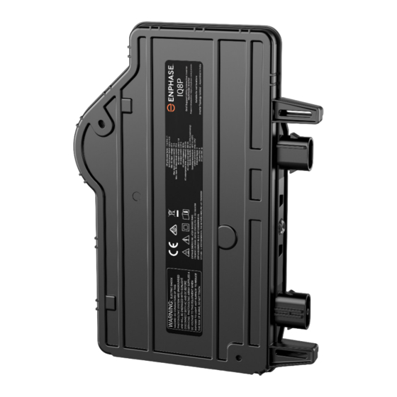
IMPORTANT: The IQ8P Microinverters include both AC and DC connectors integrated into the bulkhead. The AC port connects to IQ Cable or Enphase Field Wireable Connector. The DC port has been evaluated by TUV for intermateability with Stäubli made MC4 connectors, whose cable coupler models are “PV-KST4/…-UR, PV-KBT4/…-UR, PV-KBT4-EVO2/…-UR, and PV-KST4-EVO2/…-UR”. -
Page 12: Electricity Network Requirements
Select the correct conductor size based on the distance from the junction with the microinverter AC branch circuit to the circuit breaker in the electrical panel. Enphase recommends a voltage rise total of less than 2% for the sections from the microinverter AC branch circuit to the circuit breaker in the electrical panel. -
Page 13: Parts And Tools Required
• Enphase Installer App: Download the Enphase Installer App, open it, and log in to your Enphase account. Use it later to scan microinverter serial numbers and connect to the IQ Gateway to track the system installation progress. To download, go to https://enphase.com/en-... -
Page 14: Enphase Microinverters Installation
NOTE: Systems greater than 30 kVA require a pre-approved central disconnection device. Enphase microinverters installation Installing the IQ8P Microinverters involves several key steps. Each step listed here is detailed in the following pages. Step 1: Position the IQ Cable Step 2: Position the junction box... -
Page 15: Step 1: Position The Iq Cable
C. Provide an AC connection from the junction box/AC isolator back to the electricity network using equipment and practices by local electrical codes and standards. D. For multi-phase installations, verify the IQ Cable wiring colour codes are correctly terminated: L1-Brown, L2-Black, L3-Grey, N-Blue. © 2023 Enphase Energy Inc. All rights reserved. September 2023 IOM-00001-1.0... -
Page 16: Step 3: Mount The Microinverters
6 mm mounting hardware: 5 N m • 8 mm mounting hardware: 9 N m • When using mounting hardware from a third-party manufacturer, use the manufacturer’s recommended torque value. Horizontal mount © 2023 Enphase Energy Inc. All rights reserved. September 2023 IOM-00001-1.0... -
Page 17: Step 4: Create An Installation Map
Vertical mount >300 mm Step 4: Create an installation map The Enphase installation map is a diagram of the physical location of each microinverter in your PV array. Copy or use the Enphase installation map to record microinverter placement for the system or provide your layout if you require a larger or more intricate installation map. -
Page 18: Step 5: Manage The Cabling
IQ Sealing Caps are required for protection against moisture ingress. NOTE: If you need to remove an IQ Sealing Cap, you must use the IQ Disconnect Tool. © 2023 Enphase Energy Inc. All rights reserved. September 2023 IOM-00001-1.0... -
Page 19: Step 7: Terminate The Unused End Of The Iq Cable
IQ8P Microinverter Installation and Operation Manual Step 7: Terminate the unused end of the IQ Cable Terminate the unused end of the Enphase IQ Cable as follows: Single-phase IQ Cable Three-phase IQ Cable A. Remove 13 mm of A. Remove 20 mm of the... -
Page 20: Step 8: Complete The Installation Of The Junction Box
LED color Indicates Flashing Normal operation. AC grid function is normal and there is green communication with the IQ Gateway. IQ8P Microinverter’s LED will be flashing green only after provisioning. © 2023 Enphase Energy Inc. All rights reserved. September 2023 IOM-00001-1.0... -
Page 21: Set Up And Activate Monitoring
You can set the grid profile through the Enphase Installer Platform, during system registration, or through Enphase Installer App at any time. You must have an IQ Gateway to set or change the grid profile. For more information on setting or changing the grid profile, refer to the IQ Gateway Installation and Operation Manual at https://enphase.com/en-za/installers/resources/documentation. -
Page 22: Dc Resistance Low - Power Off Condition
DC Resistance Low – Power Off condition For all IQ8P Microinverters, a solid red status LED when DC power has been cycled indicates the microinverter has detected a DC Resistance Low – Power Off event. The LED will remain red, and the fault will continue to be reported by the gateway until the error has been cleared. -
Page 23: Troubleshoot An Inoperable Microinverter
PV module electrical compatibility with the microinverter. L. Swap DC leads with a known good, adjacent PV module. If after checking the Enphase Installer Platform periodically (this may take up to 30 minutes), the problem moves to the adjacent module, this indicates that the PV module is not functioning correctly. -
Page 24: Disconnect A Microinverter
Disconnect a microinverter If problems remain after following the troubleshooting steps listed previously, contact Enphase customer support at https://enphase.com/contact/support. If Enphase authorizes a replacement, follow the steps below. To ensure the microinverter is not disconnected from the PV modules under load, follow the disconnection steps in the order shown: A. -
Page 25: Enphase Iq Cable Planning And Ordering
Add the new microinverter serial number to the gateway database by scanning the barcode using Enphase Installer App and your device camera. d. Tap “Devices & Array” > “IQ Microinverters & Array” > “ADD DEVICES”. Scan the IQ8P Microinverter’s barcode and assign it to the array. -
Page 26: Iq Cable Options
AC cable segment end; typically, two are needed per branch circuit. • IQ Relay: single-phase (Q-RELAY-1P-INT) or multi-phase (Q-RELAY-3P-INT). For the Italy region, use IQ Relay (Q-RELAY-2-3P-ITA) for both single-phase and multi-phase applications. © 2023 Enphase Energy Inc. All rights reserved. September 2023 IOM-00001-1.0... -
Page 27: Technical Data
Technical data Technical considerations Be sure to apply the following when installing the Enphase IQ8P Microinverters System: WARNING: Risk of equipment damage. You must match the DC operating voltage range of the PV module with the allowable input voltage range of the Enphase microinverter. -
Page 28: Pq Capability Curve
IQ8P Microinverter Installation and Operation Manual PQ capability curve © 2023 Enphase Energy Inc. All rights reserved. September 2023 IOM-00001-1.0... -
Page 29: Specifications
IQ8P Microinverter Installation and Operation Manual Specifications Refer the specifications in the following table for the following IQ8P Microinverters IQ8P-72-2-INT Microinverters INPUT DATA (DC) UNITS IQ8P-72-2-INT Typical module 60-cell/120-half-cell, 66-cell/132-half-cell, 72- compatibility cell/144-half-cell, 78-cell/156-half-cell No enforced DC/AC ratio and maximum input power. - Page 30 IQ Cabling (refer to separate datasheet for cable and accessories) Pairing PV modules with wattage above the limit may result in additional clipping losses. See the compatibility calculator for suitability at https://enphase.com/en-za/installers/microinverters/calculator. © 2023 Enphase Energy Inc. All rights reserved. September 2023 IOM-00001-1.0...
- Page 31 Power line communication (PLC) 110 – 120 kHz (Class B), narrow band 200 Hz At STC within MPP range. Some of these functions require IQ Gateway Metered with current transformers and/or IQ Relay installed. © 2023 Enphase Energy Inc. All rights reserved. September 2023 IOM-00001-1.0...
-
Page 32: Enphase Installation Map
IQ8P Microinverter Installation and Operation Manual Enphase installation map © 2023 Enphase Energy Inc. All rights reserved. September 2023 IOM-00001-1.0... -
Page 33: Sample Wiring Diagram
IQ8P Microinverter Installation and Operation Manual Sample wiring diagram © 2023 Enphase Energy Inc. All rights reserved. September 2023 IOM-00001-1.0... -
Page 34: Revision History
IOM-00001-1.0 September 2023 Initial release © 2023 Enphase Energy. All rights reserved. Enphase, the e and CC logos, IQ, and certain other marks listed at https://enphase.com/trademark-usage-guidelines are trademarks of Enphase Energy, Inc. in the US and other countries. Data subject to change.
Need help?
Do you have a question about the IQ8P and is the answer not in the manual?
Questions and answers