
Related Manuals for enphase IQ8X


Summary of Contents for enphase IQ8X
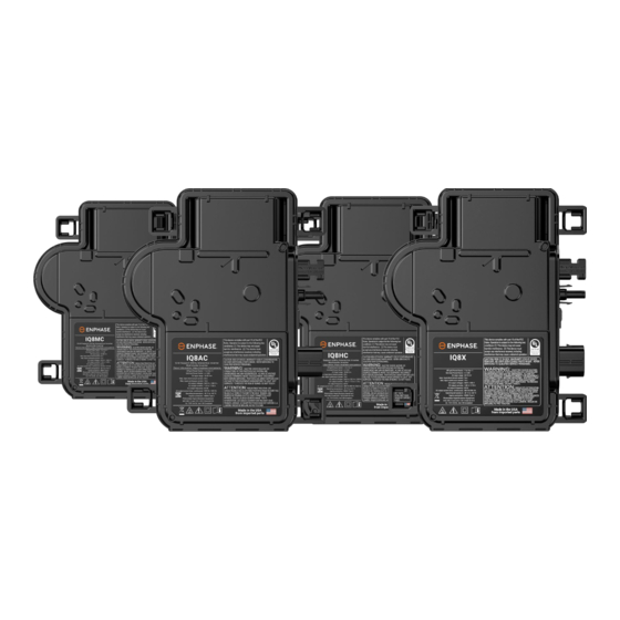
- Page 1 INSTALLATION AND OPERATION MANUAL IQ8MC, IQ8AC, IQ8HC, and IQ8X Microinverters © 2023 Enphase Energy Inc. All rights reserved. November 2023 USM-00008-2.0...
- Page 2 For warranty text refer to enphase.com/warranty. For Enphase patent information refer to enphase.com/company/patents. © 2023 Enphase Energy. All rights reserved. Enphase, the e and CC logos, IQ, and certain other marks listed at https://enphase.com/trademark-usage-guidelines are trademarks of Enphase Energy, Inc. in the US and other countries.
-
Page 3: Table Of Contents
IQ8MC, IQ8AC, IQ8HC, and IQ8X Microinverters Installation and Operation Manual Contents Important safety information ...........................5 Read this first ..............................5 Product labels..............................5 Safety and advisory symbols ........................5 IQ8 Series Microinverters safety instruction .....................5 PV rapid shutdown equipment (PVRSE) ..................... 8 Anti-islanding methodology ........................8 Enphase System .............................. - Page 4 IQ8MC, IQ8AC, IQ8HC, and IQ8X Microinverters Installation and Operation Manual Other faults .............................. 26 Troubleshoot an inoperable microinverter ..................... 26 Disconnect a microinverter ........................27 Install a replacement microinverter ......................27 Enphase IQ Cable planning and ordering ....................28 Connector spacing options ........................28 IQ Cable options ............................
-
Page 5: Important Safety Information
You must protect each microinverter AC branch circuit with a 20 A maximum breaker or fuse as appropriate. DANGER: Risk of Do not use Enphase equipment in a manner not specified by the manufacturer. Doing electric shock. so may cause death or injury to persons or damage to equipment. - Page 6 Enphase equipment and the photovoltaic (PV) equipment. Do not connect Enphase microinverters to the grid or energize the AC circuit(s) until you have completed all of the installation procedures and have received approval from the electrical utility.
- Page 7 IQ8MC, IQ8AC, IQ8HC, and IQ8X Microinverters Installation and Operation Manual WARNING: Risk of The Enphase microinverter functions only with a standard, compatible PV module with equipment appropriate fill factor, voltage, and current ratings. Unsupported devices include smart damage. PV modules, fuel cells, wind or water turbines, DC generators, non-Enphase batteries, etc.
-
Page 8: Pv Rapid Shutdown Equipment (Pvrse)
(3/8 in) in white on a red background. Anti-islanding methodology The anti-islanding methodology used by Enphase IQ8 Series Microinverters is listed by UL and tested in accordance with IEEE1547-2018 and UL1741-SB. IQ8 Series Microinverter uses the Group 1 method of anti-islanding... -
Page 9: Enphase System
Enphase IQ Microinverters over on-site AC power lines and transmits the data to Enphase App through a broadband or cellular connection. The IQ Gateway can monitor up to 600 Enphase IQ Microinverters and up to 39 IQ Batteries. -
Page 10: How The Enphase Iq8 Series Microinverters Work
PV module is produced regardless of the performance of the other PV modules in the array. While an individual PV module in the array may be affected by shading, soiling, orientation, or mismatch, each Enphase microinverter ensures top performance for its associated PV module. -
Page 11: Planning For Microinverter Installation
IQ8X-80-M-US NOTE: Some Enphase microinverters will not export power until the IQ Gateway is installed and all the microinverters are detected at the site. Additionally, the grid profile must be configured, and the IQ Gateway must have propagated these settings to the microinverters. For instructions on this procedure,... -
Page 12: Branch Circuit Capacity
When planning the system, select the appropriate AC conductor size to minimize voltage rise. Select the correct wire size based on the distance from the microinverter AC branch circuit's beginning to the load center breaker. Enphase recommends a voltage rise of less than 2% for the sections from the microinverter AC branch circuit to the breaker in the load center. -
Page 13: Lightning And Surge Suppression
For this reason, Enphase recommends that you protect your system with a lightning and/or surge suppression device. In addition to having some level of surge suppression, it is also important to have insurance that protects against lightning and electrical surges. -
Page 14: Parts And Tools Required
Enphase Installer App: Download the Enphase Installer App, open it, and log in to your Enphase Installer Platform account. Use it later to scan microinverter serial numbers and connect to the IQ Gateway to track system installation progress. To download, go to enphase.com/toolkit... -
Page 15: Enphase Microinverters Installation
IQ8MC, IQ8AC, IQ8HC, and IQ8X Microinverters Installation and Operation Manual Enphase microinverters installation Installing the IQ8 Series Microinverters involves several key steps. Each step listed here is detailed in the following pages. Step 1: Position the IQ Cable Step 2: Position the junction box... -
Page 16: Step 1: Position The Iq Cable
IQ8MC, IQ8AC, IQ8HC, and IQ8X Microinverters Installation and Operation Manual Step 1: Position the IQ Cable Plan each cable segment to allow drop connectors on the IQ Cable to align with each PV module. Allow extra length for slack, cable turns, and any obstructions. -
Page 17: Step 4: Create An Installation Map
Vertical mount Step 4: Create an installation map The Enphase installation map is a diagram of the physical location of each microinverter in your PV array. Copy or use blank map to record microinverter placement for the system, or provide your layout if you require a larger or more intricate installation map. -
Page 18: Step 5: Manage The Cabling
IQ8MC, IQ8AC, IQ8HC, and IQ8X Microinverters Installation and Operation Manual Affix serial number labels Step 5: Manage the cabling Use cable clips or tie wraps to attach the cable to the racking. Leave no more than 1.8 m (6 ft) between cable clips or tie wraps. -
Page 19: Step 7: Terminate The Unused End Of The Cable
IQ8MC, IQ8AC, IQ8HC, and IQ8X Microinverters Installation and Operation Manual WARNING: Risk of electric shock. Risk of fire. Install IQ Sealing Caps on all unused AC connectors, as these connectors become live when the system is energized. IQ Sealing Caps are required for protection against moisture ingress. -
Page 20: Step 8: Complete The Installation Of The Junction Box
208 volts or three-phase services. • IQ System Controller 2: The Enphase Energy System includes the IQ System Controller with microgrid interconnection device (MID) capability, which consolidates interconnection equipment into a single enclosure and streamlines grid-independent capabilities of PV and storage installations by providing a consistent, pre-wired solution for residential applications. - Page 21 Controller smart switch. It collects system performance information and transmits it over the internet to Enphase Cloud. An IQ Gateway is required for Enphase Energy Systems with IQ Series Microinverters. Note the IQ Gateway is included in an IQ Combiner.
- Page 22 In the PV Solar Grid Agnostic configuration in Enphase Energy System, IQ System Controller is installed on the line side of the main load panels. This allows a properly sized Enphase Energy System to provide power to all loads in the main load panel in the event of a grid outage and PV solar presence.
- Page 23 In the whole home (main load panel) backup configuration, IQ System Controller is installed on the line side of the main load panels rated up to 200 A. This allows a properly sized Enphase Energy System to provide power to all loads in the main load panel in the event of a grid outage.
- Page 24 You can set the grid profile through the Enphase Installer Platform, during system registration, or through Enphase Installer App at any time. You must have an IQ Gateway to set or change the grid profile. For more information on setting or changing the grid profile, refer to the IQ Gateway Installation and Operation Manual Enphase Support.
-
Page 25: Troubleshooting
Follow all the safety measures described in this manual. Qualified personnel can use the following troubleshooting steps if the PV system does not operate correctly. WARNING: Risk of electric shock. Do not attempt to repair the Enphase microinverter; it contains no user-serviceable parts. If it fails, contact... -
Page 26: Other Faults
Connect a clamp meter to one of the conductors of the DC cables from the PV module to measure the microinverter current. This will be under 1 A if AC is disconnected. Verify the PV module DC voltage is within the allowable range shown in "Specifications". Refer to the Enphase compatibility calculator at https://enphase.com/installers/microinverters/calculator... -
Page 27: Disconnect A Microinverter
If problems remain after following the troubleshooting steps, contact Enphase Support at Enphase Support. Enphase authorizes a replacement, follow the steps below. To ensure the microinverter is not disconnected from the PV modules under load, follow the disconnection steps in the order shown: De-energize the AC branch circuit breaker. -
Page 28: Enphase Iq Cable Planning And Ordering
Energize the AC branch circuit breaker and verify the operation of the replacement microinverter by checking the status LED on the connector side of the microinverter. Use the Enphase Installer App to retire the old microinverter serial number from the IQ Gateway database. In Enphase Installer App, once connected to the IQ Gateway: Tap Devices &... -
Page 29: Enphase Iq Cable Accessories
Technical considerations Be sure to apply the following when installing the Enphase IQ8 Series Microinverter System: WARNING: Risk of equipment damage. You must match the DC operating voltage range of the PV module with the allowable input voltage range of the Enphase microinverter. -
Page 30: Specifications
IQ8MC, IQ8AC, IQ8HC, and IQ8X Microinverters Installation and Operation Manual Specifications See the specifications in the following tables for: • IQ8MC-72-M-US Microinverters • IQ8AC-72-M-US Microinverters • IQ8HC-72-M-US Microinverters • IQ8X-80-M-US Microinverters • IQ Cable IQ8MC-72-M-US Microinverter specifications Enphase IQ8MC-72-M-US Microinverter parameters... - Page 31 IQ8MC, IQ8AC, IQ8HC, and IQ8X Microinverters Installation and Operation Manual AC short circuit fault current over three cycles Maximum microinverters per 20 A (max) AC branch circuit 240 VAC 208 VAC Total harmonic distortion <5 Overvoltage class AC port AC port backfeed current...
-
Page 32: Iq8Ac-72-M-Us Microinverter Specifications
IQ8MC, IQ8AC, IQ8HC, and IQ8X Microinverters Installation and Operation Manual IQ8AC-72-M-US Microinverter specifications Enphase IQ8AC-72-M-US Microinverter parameters Topic Unit Typical DC parameters Commonly used modules for pairing 295–500 To meet compatibility, PV modules must be within the maximum input DC voltage and maximum module I listed below. - Page 33 IQ8MC, IQ8AC, IQ8HC, and IQ8X Microinverters Installation and Operation Manual Power factor setting Grid-tied power factor (adjustable) 0.85 leading … 0.85 lagging Peak efficiency 97.3 240 VAC 208 VAC 97.2 CEC weighted efficiency 97.0 240 VAC 208 VAC 96.5 Nighttime power consumption...
-
Page 34: Iq8Hc-72-M-Us Microinverter Specifications
IQ8MC, IQ8AC, IQ8HC, and IQ8X Microinverters Installation and Operation Manual IQ8HC-72-M-US Microinverter specifications Enphase IQ8HC-72-M-US Microinverter parameters Topic Unit Minimum Typical Maximum DC parameters Commonly used modules for pairing 295–540 To meet compatibility, PV modules must be within the following maximum input DC voltage and maximum module I... - Page 35 IQ8MC, IQ8AC, IQ8HC, and IQ8X Microinverters Installation and Operation Manual Peak efficiency 97.3 240 VAC 208 VAC 97.2 CEC weighted efficiency 97.0 240 VAC 208 VAC 96.5 Nighttime power consumption 240 VAC 208 VAC Features and specifications Ambient temperature range -40°C to 65°C (-40°F to 149°F)
-
Page 36: Iq8X-80-M-Us Microinverter Specifications
IQ8MC, IQ8AC, IQ8HC, and IQ8X Microinverters Installation and Operation Manual IQ8X-80-M-US Microinverter specifications IQ8X-80-M-US Topic Typical Maximum Unit Minimum DC parameters Commonly used modules for 320–540 pairing To meet compatibility, PV modules must be within the following maximum input DC voltage and maximum module I... - Page 37 Limits may vary. Refer to local requirements to define the number of microinverters per branch in your area. IQ8X is not certified for use with Enphase Three Phase Network Protection Relay (NPR-3P-208-NA) and, therefore, designed for single-phase operation only. Check with the local utility requirements to install a single-phase inverter across three phases.
-
Page 38: Iq Cable Specifications
Enphase connector ratings Enphase connectors on the cable assemblies in the following table have a maximum current of 20 A, a maximum OCPD of 20 A, and a maximum ambient temperature of -40°C to 79°C (-40°C to 174.2°F) and are rated for disconnection under load. -
Page 39: Enphase Installation Map
IQ8MC, IQ8AC, IQ8HC, and IQ8X Microinverters Installation and Operation Manual Enphase installation map © 2023 Enphase Energy Inc. All rights reserved. November 2023 USM-00008-2.0... -
Page 40: Sample Wiring Diagram (Grid-Tied System)
IQ8MC, IQ8AC, IQ8HC, and IQ8X Microinverters Installation and Operation Manual Sample wiring diagram (grid-tied system) © 2023 Enphase Energy Inc. All rights reserved. November 2023 USM-00008-2.0... -
Page 41: Revision History
USM-00008-1.0 September 2023 Initial release. © 2023 Enphase Energy. All rights reserved. Enphase, the e and CC logos, IQ, and certain other marks listed at https://enphase.com/trademark-usage-guidelines are trademarks of Enphase Energy, Inc. in the US and other countries. Data subject to change.
Need help?
Do you have a question about the IQ8X and is the answer not in the manual?
Questions and answers