Sony IPELA NSR-1200 User Manual
Network surveillance server
Hide thumbs
Also See for IPELA NSR-1200:
- Installation manual (336 pages) ,
- User manual (138 pages) ,
- User'smanual (137 pages)
Table of Contents

Subscribe to Our Youtube Channel
Related Manuals for Sony IPELA NSR-1200


Summary of Contents for Sony IPELA NSR-1200
- Page 1 4-130-104-17 (1) Network Surveillance Server User’s Guide Software Version 1.6.3 and Later Before operating the unit, please read this manual thoroughly and retain it for future reference. NSR-1000 Series © 2008 Sony Corporation...
-
Page 2: Table Of Contents
Table of Contents Chapter 1 Introduction Overview...................6 Features and Functions ..............8 Front (When the Cover is Opened) ............8 Rear ....................... 9 System Requirements ..............10 Reference Data for Installation............. 11 Current Consumption and Inrush Current ........... 11 Storage Capacity for Recorded Data ........... 11 Number of Cameras................ - Page 3 Chapter 4 Application Settings Alarms and Events ................ 35 Displaying Configuration Window ..........36 Registering Devices ..............37 Registering Devices Manually ............37 Changing Registration Details............. 38 Deleting Devices ................. 38 Settings Required when Using SNC-CS20/CM120/DS10/DM110/ DS60/DM160................39 Registering Device Groups ..............40 Details of Each Screen ................
- Page 4 Changing Settings of Sensor Input Pins of Barionet ......92 Adding Logical Sensor Input Pins to NSR.......... 93 Deleting Logical Sensor Input Pins Created for NSR ......93 Setting Items of the [Logical Sensor In] Tab ........93 Configuring Alarm Output Settings ..........94 Changing Settings of Alarm Output Pins of NSR .......
- Page 5 For the customers in Taiwan only Trademarks • “IPELA” and are trademarks of Sony Corporation. • Microsoft, Windows, and Internet Explorer are either registered trademarks or trademarks of Microsoft Corporation in the United States and/or other countries. • The terms HDMI and HDMI High-Definition Multimedia Interface, and the HDMI Logo are trademarks or registered trademarks of HDMI Licensing LLC in the United States and other countries.
-
Page 6: Chapter 1 Introduction
Introduction Chapter Overview The NSR series is a network surveillance server for network cameras. The NSR series allows you to monitor and record JPEG, MPEG-4, and H.264 images from network cameras via the network. It also allows you to search and play back recorded images, making the NSR a truly versatile monitoring system. - Page 7 Values are based on • Audio recording and playback are also supported from Sony measurements. These values are not guaranteed, as compatible cameras. performance may change due to the user’s operating environment. • If a video loss occurs due to the network connection 2) In QuadVGA resolution (1,280 ×...
-
Page 8: Features And Functions
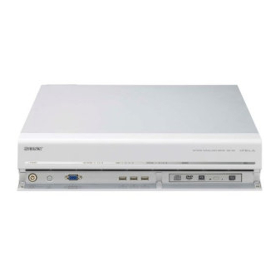
Features and Functions Front (When the Cover is Opened) NSR-1200/1100/1050H POWER NETWORK STATUS ERROR A Power LED I Monitor connector 1 Lights green when the unit is turned on. Use this connector to connect a monitor. Lights amber when it is on standby. Monitor connector 1 (and monitor connector 1 on the rear of the unit) and HDMI monitor connector 1 on the B Network LED (1 to 3) -
Page 9: Rear
Rear NSR-1200/1100 NSR-1050H A Fan E Sensor input connector Take care not to obstruct the fan grille. If the grille is Use this connector to connect the sensor input lines. obstructed, heat may build up in the unit, leading to For connection details and wiring diagrams for sensor damage and/or fire. -
Page 10: System Requirements
- Full Wide XGA (1,360 × 768) LAN4: Used for iSCSI storages - UXGA (1,600 × 1,200) 2) For details on using iSCSI storage, contact your Sony dealer. - SXGA (1,280 × 1,024) - XGA (1,024 × 768) L Monitor connectors (1 and 2) 5) Use a USB keyboard with a cable. -
Page 11: Reference Data For Installation
0.79 A NSRE-S200 220 V 0.34 A mini-SAS cable (accessory of NSRE-S200): SONY Part No. 9-885-130-46 Storage Capacity for Recorded Data You can confirm the configurations and the hard disk drive capacity of the NSR-1200/1100/1050H and optional expansion storage by clicking [Information] in the NSR- 1000 series logon screen, and viewing the Information screen that appears. -
Page 12: Chapter 2 Administration Menu
Administration Menu Chapter Overview Displaying the Administration Menu The Administration Menu allows you to change settings that were configured with the Setup Wizard when you Enter the user name and password in the logon screen, turned on the NSR for the first time, and also allows you to and click [Administration Menu]. -
Page 13: Changing Initial Settings With The Setup Menu
Details on Setting Items Changing Initial Settings with the Setup Menu Setting Items of Language Screen Select the language to display on the screens, and click [OK]. Use the Setup Menu to change settings that were configured with the Setup Wizard when you turned on the NSR for the first time. - Page 14 LAN3: iSCSI storage select the check box when synchronization of the time is not possible. 2) For details on using iSCSI storage, contact your Sony dealer. Selecting this check box forces the time to be xSetting Items of General Network Screen synchronized with the Windows NTP server.
- Page 15 xSetting Items of Network Device 1 to 3 Route Setting Configure each item, and click [OK]. Click this when you need to configure the route to another network. Configure the settings as follows on the Route For Network Device 1 screen that appears. Configure the settings as follows in accordance with your environment.
- Page 16 xSetting Items of Monitor 1 to 2 Setting Items of Disk Menu Screen Select the type and resolution of the monitor connected to Select the operation for the hard disk drive, and click this equipment, and click [OK]. [Select]. If you select [Auto], the type and resolution of the connected monitor is detected and the setting is configured automatically.
- Page 17 xSetting Items of SAS Disk List Screen check the [Storage] tab to confirm whether it is alright to Select the NSRE-S200 for which you want to configure the delete the registered storage. partition settings, and click [Partition]. When you have For details on the [Storage] tab of servers, refer to finished configuring the settings, click [OK].
- Page 18 Enable Note Select this to enable the SNMP agent function. The user name and default password are both Disable “ftptool.” Select this to disable the SNMP agent function. Setting Items of Server Name Screen Community Enter the SNMP community name. Enter the server name of NSR, and click [OK].
- Page 19 UPS Events Caution If a UPS is connected, notify when the UPS has detected a For details on automatic startup after power is restored, power cut, and when the UPS has detected recovery from contact your dealer. the power cut. Power Events Setting Items of Auto Logon Screen Notify when a power malfunction occurs.
-
Page 20: Configuring Settings Related To Servers
Setting Items of Video (Analog Camera) Configuring Settings Screen Select the video format for the analog camera to be Related to Servers connected, and click [OK]. (This screen appears when an NSR-1050H or NSBK-A16/ A16H (option) is connected.) Configure these settings when, for example, you want to change the network settings to match the network environment of the users, or you want to centralize user administration when using multiple NSR and RealShot... - Page 21 You can set one master server for uniformly managing • When the central server mode or the server port is users in the system, and multiple slave servers. changed, a message appears and the system restarts. • If you changed the network interface for the remote 1) This is for when you want to perform common user client, you must restart the system.
-
Page 22: Installing Patch Files
2) Changing the password does not guarantee prevention of log on by unauthorized users. 3) Sony Corporation is not liable for any loss of profits incurred by the customer as a result of such occurrences. The customer is responsible for configuring appropriate settings and measures. -
Page 23: Saving And Restoring Configuration Data
Confirm the content of the message, and click [Yes]. Saving and Restoring Caution Configuration Data The NSR will automatically reboot after installation of certain patch files. A confirmation screen will appear if reboot is necessary. If you cannot stop your current You can save the configuration data of NSR to external operations, select [No] to cancel installation, and media, and restore saved configuration data. -
Page 24: Periodically Saving Configuration Data
Select the media to save the configuration data, enter Select the [Weekly / Daily backup] check box, specify the file name for the configuration data, and click the day of the week and time to perform backup, and [OK]. then click [OK]. You can use alphanumeric characters and some symbols (periods (.), hyphens (-), underscores (_)) when entering the file name. - Page 25 The menu items of the Administration Menu differ Click [OK]. depending on the server and clients. The Restore Configuration screen appears. Select the location where the configuration data is saved and the configuration data, and click [OK]. Caution When configuration data is restored via the above message, the periodic backup data is restored.
-
Page 26: Exporting System Information
Exporting System Information You can save NSR system information as files onto external media. Note System information consists of NSR system configuration information and logs. Click [Export System Information] in the Administration Menu. The Export System Information screen appears. Select the media on which to save the system information, enter the file name, and then click [OK]. -
Page 27: Chapter 3 Basic Operation
Basic Operation Chapter Overview Logging On to the NSR This chapter describes how to perform the following basic Before you can use the NSR, you must first log on. operations on the NSR, including logging on, using various windows, changing the password, and turning off Press the power switch on the front or rear panel of the the unit. - Page 28 Enter the user name and password, and click [Logon]. • If you log on with the [Auto-Logon] check box selected, the logon screen will not appear the next time you start the application, and you will be logged on automatically. •...
-
Page 29: Basic Window Operations
Basic Window Operations This section provides a brief description of the basic operations for each screen. The unit includes a Main screen for monitoring images, a configuration screen for configuring various settings, and an Administration Menu for performing configurations and operations related to the NSR unit. Logon Screen Recorder Settings Screen Administration Menu... - Page 30 Administration Menu When you click [Administration Menu] in the logon screen, the Administration Menu screen appears. Click each button to perform various configurations and operations for the NSR unit. For details on settings that can be configured from the Administration Menu, see Chapter 2 “Administration Menu” (page 12).
- Page 31 Configuration screen Configure settings that are necessary for operating the NSR, such as camera registration, schedule settings, and user registration. Click the button for the item you want to configure. Returns to the Main screen. Setting items appear based on the button you clicked. For details on setting items and how to configure them, see Chapter 4 “Application Settings”...
-
Page 32: Changing The Password
Caution Changing the Password When changing the password of an administrator or a user with “User Configuration” permission, be sure to memorize the new password. You change the password for logging on to NSR. Notes • The password is extremely important to the security of this equipment. -
Page 33: Logging Off
Logging Off Locking the NSR Click in the Main screen. You can temporarily lock the screen in its current state. Use the lock function when you need to leave your seat during operation, for example. Click in the Main screen. The following screen appears. -
Page 34: Shutting Down And Restarting The Nsr
Shutting Down and Viewing Version Restarting the NSR Information Always shut down or restart the NSR from the Main Click [Information] in the logon screen. screen. Click at the top of the Main screen, and select [Shutdown] or [Reboot] from the menu that appears. The following screen appears. -
Page 35: Chapter 4 Application Settings
Application Settings Chapter Source to Recording/Action Corresponding to Alarms and Events become Event/Alarm trigger of Recording setting Action setting event/alarm Event Alarm Camera Client record record action I/O action You can configure sensor inputs, VMD, manual actions, and other triggers as alarms or events on the NSR, and Audio detection record or execute actions in response. -
Page 36: Displaying Configuration Window
Example: When [Device] is clicked: Displaying Configuration The Device Configuration screen appears. Window You can configure various settings in the Configuration window. Click (Configuration) on the top right of the main screen. The Recorder setting screen appears. Select [Advanced Setup], and click [Next]. Note Selecting [Automatic Record Settings] or [Easy Setup] allows you to register and configure cameras with a... -
Page 37: Registering Devices
The following dialog box appears. device individually. Select the channel to use, and click [OK]. Notes • When using non-Sony IP cameras (network cameras) or ONVIF (Open Network Video Interface Forum) cameras, simultaneous registration through basic configuration and automatic detection is not possible. -
Page 38: Changing Registration Details
For details on each of the items, refer to “Setting Items Note of the [General] Tab” (page 41). If registration for a camera fails, start your Web browser For details on Generic Camera, refer “Settings and connect directly to the camera to confirm that images Required when Using SNC-CS20/CM120/DS10/ from the camera are displayed. -
Page 39: Settings Required When Using Snc-Cs20/Cm120/Ds10/Dm110/ Ds60/Dm160
Example: 70 was selected for an item with an available Settings Required when Using SNC- range of 1 to 100, but the available range later CS20/CM120/DS10/DM110/DS60/ became 1 to 50 because of a function combination change, and the setting was altered to 25. DM160 •... -
Page 40: Registering Device Groups
After completing the setting procedure, check all the Removing Devices from a Group settings to make sure they are set to appropriate values. Drag the icons of the devices you want to remove from the group outside of the tree. Start operation. -
Page 41: Details Of Each Screen
Setting Items of the [General] Tab Details of Each Screen This tab allows you to change the settings of the device selected in the tree structure on the left. Setting Items of Device Configuration After configuring each item, click [Apply] to save your settings. - Page 42 Caution Caution When specifying host names, be sure to configure DNS Analog cameras without input signals will not be detected settings so that the host names can be resolved. with the automatic search. Port Network Enter the port number on the camera side for when A list of the devices connected to the network selected in connecting with the camera.
- Page 43 Password Password Enter the password for connecting to the device. Enter the password for connecting to the device. It can be up to 32 characters and ASCII characters (upper or lower Serial No. case alphanumeric characters and symbols (! " # $ % & ' ( This displays the serial number of the device.
-
Page 44: Configuring Camera Video Settings
Name Configuring Camera Enter up to 32 characters (excluding \ / : , ; * ? " < > ¦ [ ]) to assign a name to the camera to be added. Video Settings IP Address Enter the IP address or the host name for the camera. Port You can configure settings related to the images captured from a camera. - Page 45 Frame Rate Select the frame rate for images of the camera. Alarm/Event Record Configure settings related to images for when recording an alarm or event. Codec Set the image codec for the camera. Select JPEG, MPEG4 or H.264. Image Size Select the resolution for the camera.
- Page 46 Turning on the View-DR function allows the camera to Edge Storage improve the visibility of images, reducing overexposure Select this check box if the camera is equipped with an and underexposure even in high-contrast environments, Edge Storage function and you want to download the such as under backlighting, by combining the normal images stored on the camera’s Edge Storage.
- Page 47 This item can be selected when [Codec] is set to Notes [H.264] and [CBR/VBR] is set to [CBR]. • The setting items and selectable values differ depending Image Quality on the camera. In addition, some functions may be Select the image quality for the camera. limited depending on configurations.
-
Page 48: Configuring Camera Operations
Configure each item. Configuring Camera Operations In NSR, you can configure the following settings for camera operations. • “Configuring Preset Positions” (page 48) You can configure preset positions for the camera. • “Configuring Camera Tours” (page 49) You can configure camera tours for sequentially moving a camera to the pan, tilt, and zoom positions specified for presets. -
Page 49: Configuring Camera Tours
Deleting Presets Configure each item. Select the camera for which you want to delete the preset position, and click the [Preset] tab. Select the preset to delete in the list at the top of the screen, and click [Clear]. The preset is deleted. Click [Set Preset]. -
Page 50: Configuring Shadow Tours
8 Click [Test] to show and check the set tour. To Configure a New Tour Camera Tour Operation Click [Device] at the top of the Configuration screen. In NSR, the camera tour function is achieved by configuring the same stay duration and speed for each position specified by a camera preset. -
Page 51: Configuring Masks (Recorder)
The mask function works in conjunction with pan, tilt, and zoom movements only on Sony network cameras. Caution 1 If necessary, select [Freeze image during PTZ... - Page 52 Setting Items of [Mask (Recorder)] Tab Caution After configuring each item, click [Apply]. A mask area configured for a camera with pan, tilt, and zoom functions may shift when the camera is panned, tilted, or zoomed. When configuring the mask area, leave approximately 10% of additional space around the object you wish to mask.
-
Page 53: Configuring Masks (Camera)
1 Enter the name of the mask. The mask function (camera) can only be used with Sony SNC-XX600 series (XX represents two letters) network 2 Select how the mask will be displayed. -
Page 54: Configuring Control Protocols For Analog Cameras
Setting Items of [Mask (Camera)] Tab F Preview Area and Tool Buttons Use these buttons to configure the mask while checking After configuring each item, click [Apply]. the image in the preview area. (Create/Move Area) Use this button to create a rectangular mask or move a mask by dragging with the mouse. -
Page 55: Configuring Network Camera Control
Select the camera for which to enable audio, and click Administration Menu. the [Audio] tab. Configuring Network Camera Control The pan and tilt speed is adjusted automatically according to the zoom level on Sony cameras. You can configure the pan and tilt speed on ONVIF-compliant cameras. Configuring Camera Operations... -
Page 56: Settings Related To Monitoring
Configure each item, and click [Apply]. Settings Related to Monitoring You can configure the following settings related to the monitor layout and camera images. • “Configuring Monitor Layout Settings” (page 56) You can create multiple layouts according to your operating environment and objective. •... - Page 57 the Insert Background Image dialog box that Note appears, and click [OK]. “Custom Layout A” and “Custom Layout B” are preset layout groups. Use them according to your objective. The area on the left side changes to the display for setting the layout.
- Page 58 Select the layout you want to delete from the [Layout] Note tree on the Layout Configuration screen, and click Default layouts cannot be deleted. (Delete). A confirmation message appears. B Name Enter the name of the layout. It can be up to 32 characters Click [OK].
- Page 59 (Send Backward) Setting Items of Properties Use this button to move the selected image backward. x When a monitor frame is selected: (Send to Back) Use this button to move the selected image behind all • [General] Tab others. Select the camera to assign to the monitor frame. (Flip Horizontally) Use this button to flip the selected image horizontally.
- Page 60 Deinterlace Select the Video Motion Filter information to display This reduces stripes caused by interlace. This function in the monitor frame. is only enabled when the device is an NSBK-A16/ A16H and 2CIF is selected for the resolution. Object Frame Apply to All Monitor Frames This displays the object frame.
- Page 61 • [Camera Select] Tab Summary of Trigger Displays a list of triggers selected in the [Select Set the function for displaying an image of the Trigger] dialog box (page 62). specified camera in the specified monitor frame when you select the image or image map. Setting Items of Insert Template Dialog This dialog box creates a new layout.
- Page 62 Setting Items of Insert Background Image Setting Items of Insert Image Dialog Box Dialog Box This dialog box allows you to set the image file to insert. It is displayed by clicking on the Layout This dialog box imports an image such as a map or floor Configuration screen (page 58).
-
Page 63: Assigning Cameras To Monitor Frames
Configure each item. Assigning Cameras to Monitor The setting procedure is the same as that of the monitor Frames 1. Refer to step 3 (page 57) in “Creating a New Layout”. Assign a camera for displaying images to each monitor frame. - Page 64 A layout tour is added to the tree. 2 Enter a name for the tour. 3 When you want to change the display order, select a layout in the list and click (Move layout of tour up one place) or (Move layout of tour down one place).
-
Page 65: Configuring Motion Detection Settings
Using the Motion Detection Function Configuring Motion of NSR (VMD (Recorder)) Detection Settings Configure the motion detection function to use in NSR. Click [Device] at the top of the Configuration window. Motion detection is a function for detecting motion and objects from camera images or camera image metadata. - Page 66 7 Click [Apply]. D Configuration Name Enter a name for the area configuration. The motion detection area is configured, and the VMD The name you enter here is used when configuring an (recorder) setting is added to the list. alarm recording schedule to be triggered by movement in the motion detection area.
-
Page 67: (Vmd (Camera))
(Send Backward) Block Size Y Use this button to move the selected area down one Specify the vertical length of the detection area in level in a stack of overlapping areas. pixels. Increasing this value allows easier detection of vertical (Remove Polygon) movement. - Page 68 Configure each item on the [VMD] tab, and configure Note the motion detection area. The setting items C and G differ depending on the camera you are using. For details on each of the items, refer to “Setting Items I J K of [VMD] Tab (VMD (Camera))”...
- Page 69 F Preview Caution This displays the images from the camera. After an unattended object is detected (after the alarm Use the following procedure to create an area for detecting occurs), another unattended object may not be motion. detected for up to one minute. •...
-
Page 70: Detecting Motion By Metadata (Vmf)
Detecting Motion by Metadata (VMF) If the camera supports motion detection metadata, There are VMFs for motion and object detection, and up to configure settings related to the VMF (Video Motion three VMFs can be managed together as one VMF Filter) to use for motion detection by metadata. - Page 71 Click [Device] at the top of the Configuration window. The Device Configuration screen appears. Select the camera that will be the target for processing from the [Device] tree. Add the VMF package. For details on each of the items, refer to “Setting Items of [VMD] Tab (VMF)”...
- Page 72 8 Select the package to use as the default package. D Sequential The default package is used for monitoring, manual Select this option to detect specific phenomena by applying the filters in sequential order. recording, and the like at times other than for alarm The filters are applied sequentially from the left.
- Page 73 Type Notes Select the filter type. • Up to eight vertices can be set for a convex polygonal The filters that can be set differ depending on the package area. type (“Moving” or “Unattended”). • When the filter type is set to [Passing], set the direction xFor “Moving”...
- Page 74 Object Speed M Image Controls Set the speed for the object to be detected. These control the images displayed in the preview area. The operating procedure is the same as that of the main screen. Refer to “Functions and Operating Procedure of Click [Min], and enter a minimum speed for the object Main Screen”...
-
Page 75: Configuring Camera Tamper Detection And Audio Detection
1 To configure the tamper detection function, select Configuring Camera the [Tamper Detection] check box, and specify the sensitivity for detecting tampering activity on the Tamper Detection and camera. You can select from [High], [Middle], or [Low]. Audio Detection Depending on the camera model, you may not be able to specify tamper detection levels. -
Page 76: Configuring Edge Storage Settings
On the [Storage] tab, select the [Edge Storage] check Configuring Edge box, and click [Apply]. Storage Settings If the camera is equipped with an Edge Storage function, and you can configure settings for downloading the images stored on the camera’s Edge Storage. When this function is enabled and a video loss occurs during a recording schedule, video is recorded to the camera’s Edge Storage, allowing you to retrieve the data... -
Page 77: Configuring Settings Related To Storage
Select the location to add as storage, and click [OK]. Configuring Settings Related to Storage You can configure settings for storage in the storage location for image data and audio data of cameras. You can configure up to 32 storage items, and configure settings such as the maximum size of the recording file for each storage item. - Page 78 Configuring Storage for Each Recording Configure each item, and click [Apply]. Type ([Record Type] Mode) You can specify storage for each recording type, such as manual recording, schedule recording, and alarm recording. Select the server for which you want to configure storage from the [Server] tree, and click the [Storage Assign] tab.
- Page 79 A Storage List I Close This displays a list of the storage configured for the server This closes the screen. selected in the [Server] tree. Setting Items of [Storage Assign] Tab Name This displays the name of the storage. This tab is displayed by clicking [Server] in the [Configuration] window, and clicking the [Storage Capacity (%) Assign] tab.
-
Page 80: Configuring Settings Related To Deleting Recording Data
Manual Record Manual Select storage for saving for manual recording. Select storage for saving for manual recording. Schedule Record Schedule Select storage for saving for schedule recording. Select storage for saving for schedule recording. Alarm Record Alarm Select storage for saving for alarm recording. Select storage for saving for alarm recording. - Page 81 • If data overwriting is performed for the recording data of Configure each item on the [Data Cleanup] tab, and a normal recording, multiple files within one record will click [Apply]. be deleted at one time, which may result in only the recording of a certain camera being deleted at one time.
-
Page 82: Storage Configuration Example
Setting Items of the [Data Cleanup] Tab Edge Storage (days) Enter the number of storage days for Edge Storage This tab is displayed by clicking [Server] in the recording. [Configuration] window, and clicking the [Data Cleanup] tab. E Apply After configuring each item, click [Apply]. This saves the settings. - Page 83 Select [Disk], and click [Select]. Configure each item. Screen example: When internal hard disk Specify the number of partitions, select the size to allocate each partition as a percentage, and click [OK]. The Disk Menu screen appears. Select [Install], and click [Select]. Screen example: When NSRE-S200 1 Select the NSRE-S200 you want to configure, and click [Partition].
-
Page 84: Configuring Recording Schedules
segmented, it will be displayed as a different record in Configuring Recording searches and the like. 1) The number 10,000 is the total number of files since Schedules recording started. It includes files that are deleted with the cleanup and data overwrite functions. The time period segmented will differ depending on the You can configure a recording schedule for each camera to frame rate and resolution. - Page 85 Click [Recurrent] to switch to recurrent view, and For details on how to view the schedule, refer to “Setting click [New Record]. Items of Schedule Screen” (page 88). Configuring a Schedule for a Specific Date and Time You can configure a schedule for a specific date and time to specify a date and time to run a schedule.
-
Page 86: Configuring Alarm Recording And Event Recording
Configure each item, and click [OK]. Configuring Alarm Recording and The setting items differ depending on the type of Event Recording schedule. Screen example: When schedule recording You can configure alarm recording or event recording to begin recording only when an alarm occurs within the time set for the schedule. - Page 87 Changing Settings Select the camera you want to change the settings of from the [Schedule] tree on the Schedule Configuration screen. Switch to recurrent view or date view. Select the time slot (recurrent view) or schedule (date view) for which you want to change the settings, and click [Edit].
- Page 88 Setting Items of Schedule Screen Recording begins on a camera whose input pin turns on. This screen is displayed by clicking [Schedule] in the Configuration window. Screen example: When recurrent schedule (recurrent view) When [Record by selected event]: All set input pins are configured as triggers to begin recording.
- Page 89 Setting Items of New Record Dialog Box This dialog box is displayed by clicking [New Record] on the Schedule screen (page 89). The items that are displayed differ depending on the type of recording. After configuring each item, click [OK]. Screen Example: When alarm recording (recurrent schedule) •...
- Page 90 E Record Duration F Associate recording data with alarm This item is displayed in the case of alarm recording or This item is displayed for schedule recording. event recording. Select the check box to associate the recording data with Set the record duration for when an event occurs. the alarm.
-
Page 91: Configuring Sensor Inputs
H Record Camera Configuring Sensor Add the camera to become the target for recording to the list, and configure settings related to images captured from Inputs the camera. Add Device This displays the Add Device dialog box for adding a You can configure settings related to the sensor inputs device to the list. -
Page 92: Changing Settings Of Sensor Input Pins Of Camera
Configure each item on the [Physical Sensor In] tab, For details on each of the items, refer to “Setting Items and click [Apply]. of the [Logical Sensor In] Tab” (page 93). The sensor input settings are changed. Changing Settings of Sensor Input Pins of Barionet Caution •... -
Page 93: Adding Logical Sensor Input Pins To Nsr
3 Click [Apply]. Adding Logical Sensor Input Pins to The logical sensor input pin is added. The adding of a logical sensor input pin to NSR allows for linking with the external device via the network. The Deleting Logical Sensor Input Pins operation (on/off) of the added sensor input pin from the Created for NSR external device acts as a trigger to perform recording or an... -
Page 94: Configuring Alarm Output Settings
Sensor Input Pin List Configuring Alarm Output This displays a list of the sensor input pins configured for the device selected in the tree structure. Settings Enable Select the check boxes to enable the pins for the sensor inputs. You can configure settings related to the alarm outputs incorporated in NSR and cameras, and Barionet (Barix I/O Caution box) alarm outputs. -
Page 95: Changing Settings Of Alarm Output Pins Of Camera
Configure each item on the [Alarm Out] tab, and click Configure each item on the [Alarm Out] tab, and click [Apply]. [Apply]. For details on each of the items, refer to “[Alarm Out] For details on each of the items, refer to “[Alarm Out] Tab (I/O Device)”... -
Page 96: Setting Items Of The [Alarm Out] Tab
Configure each item on the [Alarm Out] tab, and click Caution [Apply]. To use alarm outputs, the alarm output pin settings on the device must also be enabled. Name Enter the names of the alarm outputs. They can be up to 32 characters long. -
Page 97: Configuring Action Settings
Name Configuring Action Enter the names of the alarm outputs. They can be up to 32 characters long. Settings Pulse Select the check box when you want to specify and enter a pulse interval. If you select this, enter the pulse In NSR, you can configure the action for when, for interval in [Pulse Duration]. - Page 98 Click (Add). Performing a Manual Action You can perform an action from the Manual Action toolbar in the main window. Display the Manual Action pane in the main window. Click in the pane at the top right of the screen, and select [Manual Action] from the menu that appears.
- Page 99 Setting Items of Manual Action Screen Camera Control Select the check box to perform an action for You can configure manual action settings. controlling the camera, and specify the control The items that are displayed differ depending on the device method.
-
Page 100: Event/Alarm Actions
[System Action] Tab Notify Emergency Event Select the check box to enable notifications for the specified emergency events. Apply This saves the settings. Cancel This cancels the changes to the settings. Event/Alarm Actions An action is performed if an alarm or event occurs within the duration set for a schedule. - Page 101 Switch to recurrent view or date view. Setting Items of New Action Dialog Box (Event/Alarm Action) Select [Action] in the tree, and select [New Action]. This dialog box is displayed by selecting [Action] from the tree in the Schedule Configuration screen, and then clicking [New Action].
- Page 102 Action Start VIDEO LOSS This displays the timing for starting the action. Select the check box to use a VIDEO LOSS event This item cannot be changed. as the trigger. Stop Action Hardware Error Select the timing for ending the action. Select the check box to use a hardware error event as the trigger.
- Page 103 Action End Preset [System Action] Tab Specify the preset position for when the action ends. Pin List Select the check boxes for the output pins to be target for performing an action to change the pin state. [I/O Device Action] Tab Send e-mail Select the check box to send a notification by mail to a specified mail address.
-
Page 104: Configuring Mail Notification Settings
Message Configuring Mail Enter the message of the mail. It can be up to 32 characters long. Notification Settings Change Layout Select the check box to change the monitor layout of monitor 1. When an event occurs, a notification can be sent by e-mail If you select this, select the monitor layout to display to a pre-registered mail address. -
Page 105: Configuring System Alert Settings
5 Enter the mail address for sending test mail. Configuring System Alert 6 After you enter each address, click [Send Test Mail] Settings and confirm that mail can be sent correctly. 7 Click [Apply]. A system alert (alarm) can be generated when camera video loss or insufficient disk space is detected. - Page 106 Configure the action to perform after a system alert B Disk Usage occurs. Select the check box to notify of insufficient remaining disk space. For details on actions, refer to “Configuring Action Target Storage List Settings” (page 97). Select the check boxes for the storage to be target for notification.
-
Page 107: Configuring Emergency Event Settings
Configuring Emergency Registering Users Event Settings You can register users in NSR, and set logon passwords and access permissions for each function. Five levels are By selecting the [Stop Recording], [VIDEO LOSS], and provided for users ranging from the administrator level [Hardware Error] check boxes in the event/alarm action (Level 5) to the view level (Level 1). -
Page 108: Configuring Default Access Permission
Permission User Level Registering a User Register the user to use NSR, and configure the Manual Action None None None permissions. Configuration Manual Deletion/ None None Click [User] at the top of the Configuration window. Protection Log Control None None Export Control None None Exit Server... -
Page 109: Changing User Settings
2 Change the user level, as necessary. Configuring Default Access Select “Custom” when you want to set the Permission permissions individually. Normally, when you add a user, access permissions for all 3 Select the check boxes for the permissions to grant existing cameras are granted to the user. - Page 110 It is displayed by clicking [User] in the Configuration Device Configuration window. Allows you to add or remove devices in the Device After configuring each item, click [Apply] to save your Configuration screen. settings. Server Configuration Allows you to configure settings related to the server and network in the Server Configuration screen.
-
Page 111: Configuring The Duration To Rewind For Quick Playback
D Servers/Cameras Access Configuring the Duration Select the check boxes for the devices or servers that the user will be permitted to access. to Rewind for Quick E Apply Playback This saves the settings. F Cancel This cancels the changes to the settings. When you click [PLAYBACK] in the Main screen, the selected monitor frame enters the playback state, and G Close... -
Page 112: Chapter 5 Operation And Control
Operation and Control Chapter Monitoring You can monitor the live images currently being captured by the camera, as well as the audio from the camera. You can also perform monitoring using the layout tour function for sequentially switching the display shown on the display at a preset time. -
Page 113: Monitoring Using Layout Tours
Monitoring Audio from Cameras Note When the Camera pane is not displayed, click If you are using a camera with support for audio input, you select [Camera] from the menu that appears to switch to can monitor the audio input from the camera. the Camera pane. -
Page 114: Functions And Operating Procedure Of Main Screen
Functions and Operating Procedure of Main Screen On the main screen, you can perform operations such as monitoring the live images captured from the current camera and playing back recorded images. A [Layout] Toolbar B [Tour] Toolbar Use this to change the layout. This is used when executing a layout tour. - Page 115 (Search Recording Data) Camera Pane This displays the Search window (page 126) for specifying search conditions. (Open Log Window) This displays the [Log] window (page 135) for displaying the recent log messages. (Volume Control) Adjust the volume for audio output from NSR. The audio of the camera of the selected monitor frame is output.
- Page 116 Manual Action Pane All Monitor Frames If you select this check box, monitoring and quick playback of live images will be applied to all monitor frames. Note The [All Monitor Frames] check box is only enabled when the total number of monitor frames in the layout is nine or less.
- Page 117 Wide-angle/Telephoto Zoom [Adjust] Tab This zooms images in the wide-angle and telephoto directions. [W] is the wide-angle end (zoom out), and [T] is the telephoto end (zoom in). Click between “W” and “T” to zoom to an absolute value. This allows you to adjust the images from the camera. If you click this button, you can perform pan, tilt, Focus zoom, and centering with the mouse.
- Page 118 When [Disable] is selected, the day/night function is (Previous Frame) disabled. This rewinds one frame. (Next Frame) I Playback Control Pane This advances one frame. (Slow Forward) This plays back images at slow speed (at 1/5x speed). (Previous Recording) This jumps to the previous recording. This is used when playing back recordings.
-
Page 119: When A Click Action Is Configured
L Alarm History Pane Second Monitor (Monitor 2) If two monitors are connect to this unit, the 1×1, 2×2, 3×2, 3×3, or 4×4 monitor layout that was specified is displayed on the monitor connected to monitor connector 2. You can also use monitor 2 as the hotspot monitor. -
Page 120: Monitor Frame
Monitor Frame Notes • In the monitor frame is set as the hotspot, the images of the corresponding camera are displayed in cases such as the following. – When the monitor frame is selected. – When there was a sensor input. –... -
Page 121: Controlling Cameras
Using Mouse to Control Camera Controlling Cameras By operating the mouse over the image displayed in a camera monitoring window, you can perform camera operations such as centering, panning, tilting, and zooming. When monitoring with a camera equipped with pan and tilt functions, you can monitor images from the camera while Select any monitor frame, and display the images of performing pan, tilt, and zoom operations on the Camera... -
Page 122: Using Camera Presets
xPerforming Zooming In and Out Operations Performing Camera Tours When using a mouse with a scroll wheel, you can zoom in and out by rotating the wheel. You can perform “tours,” in which the camera moves • Rotate the wheel forward to zoom in. successively to preset pan, tilt, and zoom positions. -
Page 123: Recording, Searching, And Playing Images
Recording, Searching, and Playing Images You can record live images, and search and play back recorded image data and audio data. This section describes the following operations. • “Recording Live Images” (page 123) You can record the images currently being captured by a camera. -
Page 124: Searching Recorded Images
specifying the playback position by date and time, and Searching Recorded Images playing from alarm history. There are the following types of search. Quick Playback • Normal Search You can specify the recording type (schedule recording, Clicking to select a monitor frame and then clicking manual recording, alarm recording, or event recording) [PLAYBACK] rewinds the recorded images by a preset and then search. - Page 125 results. For details, refer to “Playing Recorded Images from Search Results” (page 126). Object Search You can search for previously recorded images using the VMD (recorder) motion detection function and VMF function. Specify the search conditions and click [Search] in the Search Window.
-
Page 126: Playing Recorded Images From Search Results
When VMF 2 Select the check box of the recorded images you want to play. Specify the VMF package to use. 3 Click (Play). The recorded images are played in the monitor frame. You can perform operations such as enlarging, reducing, fast forwarding, and rewinding images on the Image Control pane and Playback Control pane. - Page 127 D Recording Type C Device Specification Area Specify the device for which to search. Only one device and channel can be selected. Select the check boxes of the devices for which to search in the tree. D Object Search Type Select the check boxes of the recording types for which to search.
- Page 128 B Motion Detection Area Configuration Area Configure the motion detection areas. The configuration procedure is the same as that for [VMD (Recorder)] in the Device Configuration window. For details on each of the items, refer to “Setting Items of [VMD] Tab (VMD (Recorder))” (page 66). Setting Items of Object Search Configuration Dialog Box (VMF) (List Mode)
-
Page 129: Deleting Recorded Images
Search Results Display Area (Timeline Deleting Recorded View) In the list view, each type of recording in the list of search Images results is displayed in a different color. Note You can search for the recorded images you want to delete, and then delete them manually. -
Page 130: Protecting Recorded Images
Note Protecting Recorded Protected recorded images cannot be deleted. Images A confirmation message appears. Click [Yes]. You can protect recorded images to prevent them from deletion by a cleanup, data overwrite, or unintentional The recorded images are deleted. operation. Click (Search for Recording Data) at the top of the main screen. -
Page 131: Exporting Recorded Images
Configure each item, and click [OK]. Exporting Recorded Images You can export saved recorded images as files. Video is exported in a native format (.cam file), and still images in JPEG format. Exported video can be played back with an application for playing CAM files. Exporting Recorded Images You can export saved recorded images as files. - Page 132 Click (Search for Recording Data) at the top of the main screen. Notes • If there is insufficient free space on the media, a warning message appears and exporting stops. The Search Window appears. • If you click [Close] during exporting, you can return to the main screen while continuing exporting.
-
Page 133: Exporting Recorded Images As Still Images
Setting Items of Export Dialog Box Cancel This cancels exporting, and closes the dialog box. This dialog box is displayed by clicking (Export Recorded Image) on the main screen (page 114). After configuring each item, click [OK]. Exporting Recorded Images as Still Images You can capture one scene of recorded or live images and export it as a still image file. -
Page 134: System Administration
1 Enter the file name. System Administration 2 Select the media of the export location. 3 Click [Export]. This section describes the operations necessary for routine system administration. The still image is exported. • “Shutting Down and Restarting the NSR” (page 34) •... -
Page 135: Exporting Log Files
menu at the top right. If you select [ALL], all items Click [Export]. will be displayed. The items will appear in order of priority level: EMERGENCY > ERROR > WARNING > NOTICE > ALL. The Export dialog box appears. Specify the logs you want to export, and click [OK]. When an Error Occurs with the Hardware The ERROR lamp on the front of NSR lights or flashes. - Page 136 Exporting starts. The following screen appears during exporting to allow you to confirm the progress. Note If there is insufficient free space on the media, a warning message appears and exporting stops. When exporting ends, the following screen appears. Click [Close]. The Export screen closes.
-
Page 137: I/O Port
Appendix Chapter Alarm Out I/O Port Pin NO. ALARM OUT OUT_8 – Pin Assignment of I/O Port OUT_8 + Sensor In OUT_7 – Pin NO. SENSOR IN OUT_7 + 3.3 v OUT_6 – IN_8 – OUT_6 + IN_8 + OUT_5 – OUT_5 + IN_7 –... - Page 138 Using the I/O Receptacle Note Insert a small slotted screwdriver into the upper or lower When the wiring diagram 2 is used, the NSR is not slot of the hole you want to connect a wire to (AWG No. electrically isolated, so be sure to construct external 26 to 20).
-
Page 139: Status Led
STATUS LED When an error occurs with the unit, the ERROR LED on the front panel of the unit flashes or lights depending on the error status, and the STATUS LED lights. STATUS ERROR The STATUS LED indicates the following error situations. Error codes displayed during boot stage Error codes displayed during operation stage (The ERROR LED blinks when an error occurs during... -
Page 140: Troubleshooting
• Verify whether the power cord is correctly connected. • Verify whether the monitor cable is correctly connected. Confirm that the monitor is connected to monitor Before contacting your retailer or a Sony Support Center, connector 1. please check the following items. If the problem persists, •... - Page 141 • This unit supports standard USB 2.0 Mass Storage The NSR heats up quickly devices. Depending on the type of USB 2.0 Mass • Make sure that nothing is blocking the ventilation Storage device, however, errors may occur when writing openings on the front, sides, and rear of the unit and dust data to the device.
-
Page 142: Specifications
• Always make a test recording, and verify that it was Audio output (L) (1) recorded successfully. Audio output (R) (1) SONY WILL NOT BE LIABLE FOR DAMAGES OF Audio input (1) ANY KIND INCLUDING, BUT NOT LIMITED TO, LAN (1000Base-T/100Base-TX/10Base-T) -
Page 143: Index
Registering Devices 37 Index Registering Users 107 Keyboard 13 Resolution 45 Restarting 34 Restore Configuration 24 Language 13 Action 97 Layout Configuration 58 Administration Menu 12 Layout Tours 63, 113 SAS Disk 17 Alarm Output 94 Locking the NSR 33 Save Configuration 23 Alarm Recording 86 Log Files 135...
Need help?
Do you have a question about the IPELA NSR-1200 and is the answer not in the manual?
Questions and answers