Table of Contents
Advertisement
Quick Links
Advertisement
Table of Contents
Troubleshooting

Subscribe to Our Youtube Channel
Related Manuals for Automationdirect.com Productivity 200


Summary of Contents for Automationdirect.com Productivity 200
- Page 1 Manual Number: P2-USER-M Productivity 2000 User Manual...
- Page 2 ~ WARNING ~ Thank you for purchasing automation equipment from Automationdirect.com ® , doing business as, AutomationDirect. We want your new automation equipment to operate safely. Anyone who installs or uses this equipment should read this publication (and any other relevant publications) before installing or operating the equipment.
- Page 3 Esta publicación puede contener referencias a productos producidos y/u ofrecidos por otras compañías. Los nombres de las compañías y productos pueden tener marcas registradas y son propiedad única de sus respectivos dueños. Automationdirect.com, renuncia cualquier interés propietario en las marcas y nombres de otros.
- Page 4 ~ AVERTISSEMENT ~ ® Nous vous remercions d’avoir acheté l’équipement d’automatisation de Automationdirect.com , en faisant des affaires comme, AutomationDirect. Nous tenons à ce que votre nouvel équipement d’automatisation fonctionne en toute sécurité. Toute personne qui installe ou utilise cet équipement doit lire la présente publication (et toutes les autres publications pertinentes) avant de l’installer ou de l’utiliser.
- Page 5 Productivity 2000 User Manual ® Please include the Manual Number and the Manual Issue, both shown below, when communicating with Technical Support regarding this publication. Manual Number: P2-USER-M Issue: 2nd Edition Issue Date: 08/19 Publication History Issue Date Description of Changes 1st Edition 4/15 Original...
-
Page 6: Table Of Contents
able of onTenTs Table of Contents Chapter 1 - Getting Started Before you begin...................... 1–2 Productivity Suite System Requirements ..............1–3 Step 1: Install Programming Software..............1–4 Step 2: Launch Programming Software ..............1–9 Online Help ......................1–10 Step 3: Install Hardware ..................1–11 Step 4: Apply Power to CPU ................... - Page 7 Table of Contents Power Connections ....................2–9 P2-550 Specifications ..................... 2–11 OLED Message Display ................... 2–13 Front Panel OLED Monitoring and Configuration ........... 2–14 Battery (Optional) ....................2–15 Port Specifications ....................2–16 MICRO USB Programming Port ................2–16 Ethernet Port (On bottom of CPU) ................. 2–17 Remote I/O Port (On bottom of CPU) ..............
- Page 8 Table of Contents P2-16NE3 AC/DC Sinking/Sourcing Input .............. 2–43 Wiring Diagrams ....................2–45 P2-32NE3 AC/DC Sinking/Sourcing Input .............. 2–46 Wiring Diagrams ....................2–48 P2-08NAS Isolated AC Input ................... 2–49 Wiring Diagrams ....................2–51 P2-16NA AC Input ....................2–52 Wiring Diagrams ....................2–54 P2-08TD1S Isolated Sinking DC Output ..............
- Page 9 Table of Contents P2-08TRS Isolated Relay Output ................2–91 Wiring Diagrams ....................2–93 P2-16TR Relay Output ..................... 2–94 Wiring Diagrams ....................2–96 Chapter 3 - Analog I/O Specifications Analog I/O Modules Overview .................. 3–3 Analog I/O Modules ....................3–4 Analog Input Modules ....................3–4 Analog Output Modules ...................
- Page 10 Table of Contents P2-16AD-2 Voltage Analog Input ................3–35 Wiring Diagrams ....................3–37 Module Configuration .................... 3–38 OLED Panel Display ....................3–39 P2-16ADL-1 Current Analog Input ................3–40 Wiring Diagrams ....................3–42 Module Configuration .................... 3–43 P2-16ADL-2 Voltage Analog Input ................3–44 Wiring Diagrams ....................
- Page 11 Table of Contents P2-08DA-1 Current Analog Output ................. 3–80 Wiring Diagrams ....................3–82 Module Configuration .................... 3–83 OLED Panel Display ....................3–84 P2-08DA-2 Voltage Analog Output ................. 3–85 Wiring Diagrams ....................3–87 Module Configuration .................... 3–88 OLED Panel Display ....................3–89 P2-08DAL-1 Current Analog Output ...............
- Page 12 Table of Contents P2-8AD4DA-2 Voltage Analog Input/Output ............3–122 Wiring Diagrams ....................3–125 Module Configuration ..................3–126 OLED Panel Display ....................3–127 P2-HSI High-Speed Input Module Overview ............4–2 HSI LED Indicators ....................4–3 HSI Input Specifications .................... 4–4 HSI Status Output Specifications ................4–6 Frequency Response ....................
- Page 13 Table of Contents Dimensions and Installation ..................5–6 Base Dimensions, inches [mm] ................. 5–6 Mounting Guidelines ....................5–7 Enclosures ........................ 5–7 Mounting Position ....................5–7 Mounting Clearances ....................5–7 Grounding ....................... 5–7 Temperature Considerations ..................5–7 Power Considerations ....................5–7 Panel Layout ......................
- Page 14 Table of Contents Relay Outputs - Wiring Methods ................5–27 Relay Outputs – Transient Suppression for Inductive Loads in a Control System ..5–28 Chapter 6 - Communications Communications ......................6-1 Communication Ports ....................6-1 Communications: Connectivity ................. 6-8 P2-550 Port Connections ..................6-8 ASCII and Custom Protocol Functionality ...............
- Page 15 Table of Contents EtherNet/IP I/O Message Troubleshooting: ............6-45 EtherNet/IP Explicit Message Troubleshooting: ............6-45 ProNET ........................6-46 Custom Protocol over Ethernet Functionality ............6-47 Hardware Configuration ..................6-48 Custom Protocol Ethernet Instruction ..............6-49 Communications: Remote I/O and GS-Drives ............6-50 Things To Consider for the design of Remote I/O and GS-Drives ......
- Page 16 Table of Contents PWR Indicator ......................7–5 Incorrect Base Power ....................7–5 Faulty CPU ....................... 7–5 Device or Module Causes the Power Supply to Shutdown ........7–6 Run Indicator ......................7–7 CPU Indicator ......................7–7 Communications Problems ..................7–7 I/O Module Troubleshooting ..................7–8 Things to Check .......................
- Page 17 Table of Contents Basic EMC Installation Guidelines ................A–4 Enclosures ........................A–4 Mains Filters ......................A–5 Suppression and Fusing ....................A–5 Internal Enclosure Grounding ...................A–5 Equipotential Grounding ..................A–5 Communications and Shielded Cables ..............A–6 Analog and RS232 Cables ..................A–7 Multidrop Cables ......................A–7 Shielded Cables Within Enclosures................A–7 Analog Modules and RF Interference ................A–7 Network Isolation .....................A–8 Items Specific to the Productivity...
- Page 18 hapter hapter hapter ettinG tarted In This Chapter... Before you begin...................... 1–2 Productivity Suite System Requirements ..............1–3 Step 1: Install Programming Software..............1–4 Step 2: Launch Programming Software ..............1–9 Online Help ......................1–10 Step 3: Install Hardware ..................1–11 Step 4: Apply Power to CPU ...................
-
Page 19: Chapter 1: Getting Started
Productivity Suite USB-A to Micro USB-B Windows OS Programming Software Programming Cable PS-PGMSW Not available from Automationdirect.com Download software from our webste at: www.automationdirect.com under “Programmable Controllers”. AC Power Cord Wire Strippers Screwdriver Hookup Wire DN-WS TW-SD-MSL-1 Not available from Automationdirect.com. -
Page 20: Productivity Suite System Requirements
Productivity Suite System Requirements Productivity Suite, a Windows-based programming software, is available as a FREE download at https://support.automationdirect.com/downloads.html. Please check our website for your product’s current operating systems requirements. NOTE: USB or Ethernet cable is also required for communications between PC and CPU. -
Page 21: Step 1: Install Programming Software
Chapter 1: Getting Started Step 1: Install Programming Software 1. Download the latest version of the Productivity Suite Programming Software from the Automationdirect website. Or, if the Productivity Suite Programming Software CD is available, insert it into your PC CD drive. - Page 22 Chapter 1: Getting Started 4. Carefully read the software license agreement. If you agree to the terms and conditions of this agreement, select the “I accept the terms of the License Agreement” and then the “Next” button. 5. The “Choose Install Folder” window will open next. If this is the first installation of the Productivity Suite Software on your PC, choose (a) Install New Instance: This option will install a new instance of the Productivity Suite software in the default location, C:\Program Files\AutomationDirect\Productivity Suite...
- Page 23 Chapter 1: Getting Started 1–6 Productivity Hardware User Manual, 2nd Edition 2000...
- Page 24 Chapter 1: Getting Started 6. Once you have selected the install folder and whether or not to delete any previous instances, the “Choose Shortcuts” window will appear. If a Shortcut Icon is desired for the software select the location where the icon will be created. The default location is “On the Desktop”.
- Page 25 Chapter 1: Getting Started 8. The next screen to appear contains the Release Notes for this version of the Productivity Suite software. This is an opportunity to review the software version release notes. You may read these before selecting the “Next” button. 9.
-
Page 26: Step 2: Launch Programming Software
Chapter 1: Getting Started Step 2: Launch Programming Software After installing the Productivity Suite Programming Software, PS-PGMSW, launch the software by double clicking the desktop Productivity Suite Icon. Or from the PC’s ‘Start’ menu, slide the mouse pointer through the menus (start>All Programs>AutomationDirect>Productivity Suite x.x.x.x>Productivity Suite) to the Productivity Suite Programming Software selection, and use the left mouse button to click on it. -
Page 27: Online Help
Chapter 1: Getting Started The Programming Window is divided into menus and toolbars that work together to make project development as simple as possible. Online Help It is essential that you use the Productivity Suite online Help to familiarize yourself with the software. -
Page 28: Step 3: Install Hardware
Chapter 1: Getting Started Step 3: Install Hardware The Productivity 2000 CPU system components snap together to form a configured CPU ® in minutes. See Chapter 5, Installation and Wiring, for more detailed hardware installation information. What follows are the basic steps: 1. - Page 29 Chapter 1: Getting Started 3. Install I/O Modules and engage locking tabs. Locked Unlocked 4. Connect appropriate wiring to the power supply (P2-01AC) and I/O (P2-08TRS module) in this example. AC(L) AC(N) LOGIC LO O G The power supply and load Load are connected through an AC Power Supply...
- Page 30 Chapter 1: Getting Started 5. Connect USB cable. Use a Micro USB cable with a Type A and Micro Type B connectors as shown below. Productivity 1–13 Hardware User Manual, 2nd Edition 2000...
-
Page 31: Step 4: Apply Power To Cpu
Chapter 1: Getting Started Step 4: Apply Power to CPU Ensure proper wiring and the correct voltage is available before connecting wiring to the power supply. Once this is verified, connect power to the power supply. Once power is applied, the CPU will perform a self evaluation and verification. -
Page 32: Step 5: Establish Pc To Cpu Communications
Chapter 1: Getting Started Step 5: Establish PC to CPU Communications Select “Choose CPU” icon on the CPU Toolbar and the dialog box shown below will appear. Highlight the installed CPU listed in the dialog box and select “Connect”. When initially going Online with the CPU, a popup window will notify you of a project difference between the CPU and the PC. -
Page 33: Step 6: Open/Read Hardware Configuration
Chapter 1: Getting Started Step 6: Open/Read Hardware Configuration Before we create a project we must configure the hardware so we’ll have default input and output tags for use in our project. With the CPU in “STOP” Mode, select Hardware Configuration under Application Tools and the following screen opens. - Page 34 Chapter 1: Getting Started This screen shows the user tag names for all sixteen I/O points. Select “OK”. Productivity 1–17 Hardware User Manual, 2nd Edition 2000...
-
Page 35: Step 7: Create A Project
Chapter 1: Getting Started Step 7: Create a Project We’re going to start by entering a simple ladder logic program in the order that follows. Rung #1 Select the “END” position on Rung #1 with your cursor. From the Instruction List on the right, scroll down to Counters/Timers section and double click on the Simple Timer (STMR) instruction. - Page 36 Chapter 1: Getting Started Place the cursor on the first position on Rung #1 as shown below. In the Instruction List on the right, scroll up to Contacts section and double click on “NO Contact (NO)”. A NO Contact (NO) is placed at this rung position and a dialog box pops up. 1.
- Page 37 Chapter 1: Getting Started With the cursor on Rung #1, to the right of contact ‘T1_Start’, we are going to begin drawing a branch circuit. Under the Edit drop down menu, select “Wire”, then select “Down”. Notice that a wire has been added. NOTE: There is also a wire Erase With Cursor tool in the Edit drop down menu that is used to erase any lines that were created using the Wire tools.
- Page 38 Chapter 1: Getting Started Next we’ll draw a wire to the left. Under the Edit drop down menu, select “Wire”, then select “Left”. Next we’ll add another normally-open contact. Place the box cursor on the first position on the newly created SubRung #1. From the Instruction List click & drag a Contact (NO) into this box.
- Page 39 Chapter 1: Getting Started Rung #2 Next we’ll add another normally-open contact at the start of Rung #2. Click & drag a “NO Contact (NO)” into this box. A NO Contact (NO) dialog box pops up. 1. In the empty tag field press the down arrow on the right to open a drop-down list; scroll down and select ‘T1_DN’.
- Page 40 Chapter 1: Getting Started The ladder program now looks like this. When either of the T1 contacts are energized, the timer starts. When it times out, contact T1_DN energizes and turns on the rung 2 output. Productivity 1–23 Hardware User Manual, 2nd Edition 2000...
-
Page 41: Step 8: Save Project
Chapter 1: Getting Started Step 8: Save Project Save the project by opening the File drop-down menu and selecting Save Project. 1–24 Productivity Hardware User Manual, 2nd Edition 2000... -
Page 42: Step 9: Write Project To Cpu
Chapter 1: Getting Started Step 9: Write Project to CPU Next we will transfer the project to the CPU. Transfer Project is accessed by selecting Transfer Project from the File Menu. Select “To CPU” from the Transfer Project menu. The project will then be Transferred to the CPU from the PC. During the transfer a status window will open displaying the process. -
Page 43: Step 10: Place Cpu In Run Mode
Chapter 1: Getting Started Step 10: Place CPU in RUN Mode Next, verify the Run/Stop switch on the CPU faceplate is placed in the Run position and then place the CPU in RUN mode on the Productivity Software Toolbar so the ladder logic program executes. -
Page 44: Step 11: Test The Project Using Monitor Mode
Chapter 1: Getting Started Step 11: Test the Project Using Monitor Mode In this next step, use the Monitor Mode and Data View to test the ladder logic program. Select Monitor Mode from the top of the Ladder Logic screen to display the status of Boolean and Integer Tags. - Page 45 Chapter 1: Getting Started The tags will be placed in a separate Tab titled New Task - STMR as seen below. The remaining tagnames in the Ladder Logic can be added to the Data View window by clicking on a blank area in the Tagname column. This will display a drop down menu where the tags can be selected.
- Page 46 Chapter 1: Getting Started Once all of the tagnames have been added, they can now be monitored and manipulated. See the Data View help file topic for additional details if needed. NOTE: Force must be enabled for a Tag in the Tag Database before Force can be used in Data View. Productivity 1–29 Hardware User Manual, 2nd Edition...
- Page 47 hapter hapter hapter pecificationS In This Chapter... Overview ........................2–3 P2-01AC and P2-01DCAC Power Supply ..............2–6 Remote Slave Module ....................2–21 I/O Modules Overview .................... 2–28 Discrete I/O Modules ....................2–29 P2-08SIM Input Simulator Module ................. 2–30 Discrete Input Modules ..............2–30 P2-08ND3-1 Sinking/Sourcing DC Input..............
- Page 48 Table of Contents P2-16TD1P Sinking Protected DC Output .............. 2–73 P2-16TD2P Sourcing Protected DC Output ............2–76 P2-32TD1P Sinking Protected DC Output .............. 2–79 P2-32TD2P Sourcing Protected DC Output ............2–82 P2-08TAS Isolated AC Output ................. 2–85 P2-16TA AC Output ....................2–88 P2-08TRS Isolated Relay Output ................
-
Page 49: Chapter 2 - Specifications
Chapter 2: Specifications Overview Base Hardware The Productivity 2000 system is a modular system that requires a base to accommodate the ® various modules. Bases are available in sizes of 4, 7, 11 and 15 I/O module slots. The base contains additional dedicated slots for the power supply and the CPU unit. -
Page 50: Base Configuration
Chapter 2: Specifications P2-04B, P2-07B, P2-11B, P2-15B Bases The P2-04B, P2-07B, P2-11B, and P2-15B are 4, 7, 11, and 15-slot, local, expansion, and remote I/O bases. P2-04B 4-Slot Base NOTE: See Chapter 5 for base dimensions. Base Configuration Remote IO address rotary switches... - Page 51 Chapter 2: Specifications Base Specifications Input or Output Modules per Base 4, 7, 11, or 15 Power Supply Slots 1 (P2-01AC or P2-01DCAC) CPU Slots 1 (P2-550) Module Types Supported Discrete, analog and specialty None. Any I/O module may be installed in Module Placement Restrictions any I/O slot without power supply budget or module type restrictions.
-
Page 52: P2-01Ac And P2-01Dcac Power Supply
Chapter 2: Specifications P2-01AC and P2-01DCAC Power Supply There are two power supplies available; both provide isolated 24VDC and 3.3 VDC to the Productivity 2000 bases. ® The P2-01AC input power supply requires power from an external 100–240 VAC source. The P2-01DCAC input power supply requires power from an external 24VAC or 12–24 VDC source. -
Page 53: P2-01Ac Power Supply
Chapter 2: Specifications P2-01AC Power Supply User Specifications Input Voltage Range (Tolerance) 100 to 240 VAC (-15% / +10%) 50 to 60Hz with ±5% tolerance Rated Operating Frequency P2-01AC Maximum Input Power 37.4 W Cold Start Inrush Current 23.6 A 25.6 A Maximum Inrush Current (Hot Start) Micro fuse 250V, 2A... -
Page 54: P2-01Dcac Power Supply
Chapter 2: Specifications P2-01DCAC Power Supply P2-01DCAC User Specifications 24VAC 12–24 VDC Input Voltage Range (Tolerance) (-10% / +20%) (-10% / +20%) Maximum Input Power 72VA P2-01DCAC Maximum Input Ripple Less than ±5% 45A, 4µS @ 24VDC Cold Start Inrush Current Maximum Inrush Current (Hot Start) Same as Cold Start Inrush Current 50 to 60Hz with ±5% tolerance... -
Page 55: Power Connections
Chapter 2: Specifications Power Connections P2-01DCAC P2-01AC P2-01AC P2-01DCAC P2-01AC 100–240 VAC 12-24VDC 24VAC AC(L) AC(L) AC(N) AC(N) LOGIC LOGIC LOGIC LOGIC Grounding A good common ground reference (earth ground) is essential for proper operation of the Productivity 2000 ® system. - Page 56 Chapter 2: Specifications Productivity 2000 CPU Module ® Each Productivity2000 system base requires one CPU module be mounted in the controller slot of the unit. The CPU stores and executes the user’s program. P2-550 Productivity 2–10 Hardware User Manual, 2nd Edition 2000...
-
Page 57: P2-550 Specifications
Chapter 2: Specifications P2-550 Specifications OLED - 4 x 10 character - 8 control buttons - User defined messages - User adjustable settings CPU Status Indicators - System errors / information 10/100 MB Micro SD CARD Ethernet Port - Data Logger - Programming - Project Transfer - Online monitoring... - Page 58 Chapter 2: Specifications CPU Specifications* User Memory 50MB (Includes program, data and documentation) Memory Type Flash and Battery Backed RAM Retentive Memory 500kB Scan Time 500µs (3K Boolean, 240 I/O) OLED, 4x10 characters, 8 control buttons; Display OLED characters are 7x12 with a dot pitch of 0.245 mm;...
-
Page 59: Oled Message Display
Chapter 2: Specifications OLED Message Display The P2-550 CPU incorporates a 4 line by 10 character OLED for system alarms, information and for displaying user-defined messages. OLED characters are 7x12 (1.72 mm x 2.94 mm) with a dot pitch of 0.245 mm. OLED control buttons located beneath the display allow the user to navigate through menu items. -
Page 60: Front Panel Oled Monitoring And Configuration
Chapter 2: Specifications Front Panel OLED Monitoring and Configuration Productivity 2–14 Hardware User Manual, 2nd Edition 2000... -
Page 61: Battery (Optional)
Chapter 2: Specifications Battery (Optional) A battery is included with the P2-550 CPU module, but is not installed. The battery may be installed in order to retain the Time and Date along with any Tagname values that are set up as retentive. The battery is not needed for program backup. -
Page 62: Port Specifications
Chapter 2: Specifications Port Specifications The P2-550 CPU has several communications ports and the following pages contain their specifications and pin-out diagrams. P2-550 MICRO USB Programming Port Used exclusively for connecting to a PC running the ProductivitySuite programming software. Micro USB Input Specifications Port Name MICRO USB Standard Micro USB Slave input for programming and... -
Page 63: Ethernet Port (On Bottom Of Cpu)
Chapter 2: Specifications P2-550 Ethernet Port (On bottom of CPU) RJ-45 style connector used for: • Connection to a PC running the ProductivitySuite programming software • Modbus TCP Client (32 Servers) connections (Modbus requests sent from the CPU) • Modbus TCP Server (16 Clients) connections (Modbus requests received by the CPU) •... -
Page 64: Micro Sd Slot
Chapter 2: Specifications P2-550 MICRO SD SLOT Used for data logging or project transfers. Micro SD Specifications Port Name MICRO SD Standard Micro SD socket for data logging or Description program transfer Maximum Card 32GB Capacity Mbps Minimum Typical Maximum Transfer Rate (ADATA microSDHC Read... -
Page 65: Rs-232 Port
Chapter 2: Specifications P2-550 RS-232 Port RJ-12 style connector used for: • Modbus RTU Master connections • Modbus RTU Slave connections • ASCII full or half duplex communications • Custom Protocol Incoming and Outgoing communications RS-232 Specifications Port Name RS-232 Non-isolated RS-232 DTE port connects the CPU as a Description Modbus/ASCII master or slave to a peripheral device. - Page 66 Chapter 2: Specifications RS-485 Port P2-550 A 3-pin removable terminal block used for: • Modbus RTU Master connections • Modbus RTU Slave connections • ASCII Incoming and Outgoing communications • Custom Protocol Incoming and Outgoing communications RS-485 Port Specifications Port Name RS-485 Non-isolated RS-485 port connects the CPU as a Modbus/ASCII master or slave to a peripheral...
-
Page 67: Remote Slave Module
Chapter 2: Specifications Remote Slave Module The P2-RS is high-performance Remote Slave module. The module features several communications ports which support Ethernet Remote I/O, and serial devices. The P2-RS also includes a 4 line x 10 character OLED display and an additional USB IN (Mini USB type A) port for remote CPU programming and monitoring. -
Page 68: P2-Rs Remote Slave Module Example
Chapter 2: Specifications P2-RS Remote Slave Module Example Add up to 8 Remote Bases using P2-RS Slave modules and up to 16 GS Drives on the Remote I/O Ethernet Network P2-RS P2-RS P2-550 SE-SW5U GS-EDRV100 SE-SW5U Productivity 2–22 Hardware User Manual, 2nd Edition 2000... -
Page 69: P2-Rs Remote Slave Module Specifications
Chapter 2: Specifications P2-RS Remote Slave Module Specifications Remote Slave Specifications Mounting Location Controller slot in remote base OLED, 4x10 characters, backlit, 1 OLED wake up button, OLED characters are 7x12 with a dot pitch of Display 0.245 mm; 1.72 mm x 2.94 mm USB IN: (2.0, Type B) Programming, Monitoring, Debug P2-RS REMOTE SLAVE REMOTE I/O: (10/100 Mbps Ethernet) 1 P2-550... -
Page 70: P2-Rs Remote Slave Module Front Panel
Chapter 2: Specifications P2-RS Remote Slave Module Front Panel OLED - 4 x 10 character - User defined alarms/ messages - User adjustable settings - System errors / information P2-RS REMOTE SLAVE OLED Wake-up Button USB 2.0 Port (Micro USB type B) Status Indicators - Programming - Online monitoring... -
Page 71: Oled Message Display
Chapter 2: Specifications OLED Message Display The P2-RS incorporates a 4 line x 10 character OLED for system errors and information or for displaying user- defined messages. OLED characters are 7x12 with a dot pitch of 0.245 mm; 1.72 mm x 2.94 P2-RS REMOTE SLAVE P2-RS REMOTE SLA Wake Up button refreshes... -
Page 72: Setting Remote Slave Address
Chapter 2: Specifications Setting Remote Slave Address Each Remote Slave must have a unique address between 1 and 99. The address is set using the two rotary switches located in the base; X10 for setting the tens units and X1 for setting the ones unit. -
Page 73: Setting The Remote Slave Address (Continued)
Chapter 2: Specifications Setting the Remote Slave Address (continued) It is also necessary to configure the remote addresses using the ProductivitySuite Programming Software. For example, if connected online to a Productivity 2000 system with slaves installed, go ® to Hardware Configuration and select the Read Configuration (1) icon. The CPU will automatically read the addresses of the remote slaves and add them to the configuration. -
Page 74: I/O Modules Overview
Chapter 2: Specifications I/O Modules Overview A variety of discrete and analog I/O modules are available for use in the P2000 System. Each I/O module is identified as an “Input”, “Output”, or “Input/Output” module on its front panel using the color coding scheme listed below. See the following pages for discrete I/O module specifications, Chapter 3 for analog I/O module specifications and Chapter 4 for specialty module specifications. -
Page 75: Discrete I/O Modules
Chapter 2: Specifications Discrete I/O Modules Discrete Input Modules Productivity2000 Discrete Input Modules Number of Part Number Description See Page Inputs P2-08SIM Input Simulator Module 2-30 P2-08ND3-1 Sinking/Sourcing 12–24 VDC 2-31 P2-16ND3-1 Sinking/Sourcing 12–24 VDC 2-34 P2-32ND3-1 Sinking/Sourcing 12–24 VDC 2-37 P2-08NE3 Sinking/Sourcing 24V AC/DC... -
Page 76: P2-08Sim Input Simulator Module
Chapter 2: Specifications P2-08SIM Input Simulator Module The P2-08SIM Input Simulator Module provides 8 toggle switches to simulate input devices. Input Specifications Inputs per Module 8 Internal switches OFF to ON Response Max. 20ms ON to OFF Response Max. 20ms Status Indicators Logic Side (8 points) General Specifications... -
Page 77: P2-08Nd3-1 Sinking/Sourcing Dc Input
Chapter 2: Specifications P2-08ND3-1 Sinking/Sourcing DC Input The P2-08ND3-1 Module provides eight 12–24 VDC sinking/sourcing inputs. Input Specifications Inputs per Module 8 (Sinking/Sourcing) D3-1 Voltage Rating 12–24 VDC Input Voltage Range 10.2–26.4 VDC Peak Voltage 30VDC 3.5 mA @ 12VDC Input Current 7.5 mA @ 24VDC 12–... - Page 78 Chapter 2: Specifications P2-08ND3-1 Sinking/Sourcing DC Input, (continued) General Specifications Operating Temperature 0° to 60°C (32° to 140°F), Storage Temperature -20° to 70°C (-4° to 158°F) Humidity 5 to 95% (non-condensing) Environmental Air No corrosive gases permitted Vibration IEC60068-2-6 (Test Fc) Shock IEC60068-2-27 (Test Ea) Field to Logic Side Isolation...
-
Page 79: Wiring Diagrams
Chapter 2: Specifications P2-08ND3-1 Sinking/Sourcing DC Input (continued) Wiring Diagrams 12–24 VDC 12–24 VDC Equivalent Input Circuit Internal Module Circuitry 12–24 VDC Optical Isolator INPUT Productivity 2–33 Hardware User Manual, 2nd Edition 2000... -
Page 80: P2-16Nd3-1 Sinking/Sourcing Dc Input
Chapter 2: Specifications P2-16ND3-1 Sinking/Sourcing DC Input The P2-16ND3-1 Input Module provides sixteen inputs for switches and other devices connected to ground or to supplies ranging from 12–24 VDC. Input Specifications D3-1 Inputs per Module 16 (Sink/Source) Voltage Rating 12–24 VDC Input Voltage Range 10.2–26.4 VDC Peak Voltage... - Page 81 Chapter 2: Specifications P2-16ND3-1 Sinking/Sourcing Input (continued) General Specifications Operating Temperature 0° to 60°C (32° to 140°F), Storage Temperature -20° to 70°C (-4° to 158°F) Humidity 5 to 95% (non-condensing) Environmental Air No corrosive gases permitted Vibration IEC60068-2-6 (Test Fc) Shock IEC60068-2-27 (Test Ea) Field to Logic Side Isolation...
-
Page 82: Wiring Diagrams
Chapter 2: Specifications P2-16ND3-1 Sinking/Sourcing Input (continued) Wiring Diagrams 12–24 VDC 12–24 VDC Equivalent Input Circuit Internal Module Circuitry 12–24 VDC Optical Isolator INPUT Productivity 2–36 Hardware User Manual, 2nd Edition 2000... -
Page 83: P2-32Nd3-1 24Vdc Sinking/Sourcing Input
Chapter 2: Specifications P2-32ND3-1 24VDC Sinking/Sourcing Input The P2-32ND3-1 DC Input Module provides thirty-two sinking/sourcing 12–24 VDC inputs for use with the Productivity 2000 System. ® Input Specifications Inputs per Module 32 (Sink/Source) D3-1 Voltage Rating 12–24 VDC Input Voltage Range 10.2–26.4 VDC Peak Voltage 30VDC... - Page 84 Chapter 2: Specifications P2-32ND3-1 24VDC Sinking/Sourcing Input (continued) General Specifications Operating Temperature 0° to 60°C (32° to 140°F) Storage Temperature -20° to 70°C (-4° to 158°F) Humidity 5 to 95% (non-condensing) Environmental Air No corrosive gases permitted Vibration IEC60068-2-6 (Test Fc) Shock IEC60068-2-27 (Test Ea) Field to Logic Side Isolation...
-
Page 85: Wiring Diagrams
Chapter 2: Specifications P2-32ND3-1 24VDC Sinking/Sourcing Input (continued) Wiring Diagrams 12–24 VDC 12–24 VDC 12–24 VDC 12–24 VDC Equivalent Input Circuit Internal Module Circuitry 12–24 VDC Optical Isolator INPUT Productivity 2–39 Hardware User Manual, 2nd Edition 2000... -
Page 86: P2-08Ne3 Ac/Dc Sinking/Sourcing Input
Chapter 2: Specifications P2-08NE3 AC/DC Sinking/Sourcing Input The P2-08NE3 AC/DC Input Module provides eight 24V AC or DC sinking/sourcing inputs. Input Specifications Inputs per Module 8 (Sinking/Sourcing) Voltage Range 24V AC/DC Input Voltage Range 20.4–27.6 VAC/VDC Peak Voltage 27.6 VAC/ 30VDC AC Frequency 47–63 Hz Input Current (Typical) - Page 87 Chapter 2: Specifications P2-08NE3 AC/DC Sinking/Sourcing Input, (continued) General Specifications Operating Temperature 0° to 60°C (32° to 140°F), Storage Temperature -20° to 70°C (-4° to 158°F) Humidity 5 to 95% (non-condensing) Environmental Air No corrosive gases permitted Vibration IEC60068-2-6 (Test Fc) Shock IEC60068-2-27 (Test Ea) Field to Logic Side Isolation...
-
Page 88: Wiring Diagrams
Chapter 2: Specifications P2-08NE3 AC/DC Sinking/Sourcing Input (continued) Wiring Diagrams 24 VAC 24 VDC 24 VAC 24 VDC Equivalent Input Circuit Internal Module Circuitry 24VAC 24 VDC Optical Isolator INPUT Productivity 2–42 Hardware User Manual, 2nd Edition 2000... -
Page 89: P2-16Ne3 Ac/Dc Sinking/Sourcing Input
Chapter 2: Specifications P2-16NE3 AC/DC Sinking/Sourcing Input The P2-16NE3 AC/DC Input Module provides sixteen 24V AC/DC sinking or sourcing inputs with four isolated commons. Input Specifications Inputs per Module 16 (Sinking/Sourcing) Operating Voltage Range 24V AC/DC Input Voltage Range 20.4–27.6 VAC/VDC Peak Voltage Range 27.6 VAC/ 30VDC AC Frequency... - Page 90 Chapter 2: Specifications P2-16NE3 AC/DC Sinking/Sourcing Input (continued) General Specifications Operating Temperature 0° to 60°C (32° to 140°F), Storage Temperature -20° to 70°C (-4° to 158°F) Humidity 5 to 95% (non-condensing) Environmental Air No corrosive gases permitted Vibration IEC60068-2-6 (Test Fc) Shock IEC60068-2-27 (Test Ea) Field to Logic Side Isolation...
-
Page 91: Wiring Diagrams
Chapter 2: Specifications P2-16NE3 AC/DC Sinking/Sourcing Input (continued) Wiring Diagrams 24 VAC 24 VDC 24 VAC 24 VDC Equivalent Input Circuit Internal Module Circuitry 24VAC 24 VDC Optical Isolator INPUT Productivity 2–45 Hardware User Manual, 2nd Edition 2000... -
Page 92: P2-32Ne3 Ac/Dc Sinking/Sourcing Input
Chapter 2: Specifications P2-32NE3 AC/DC Sinking/Sourcing Input The P2-32NE3 AC/DC Input Module provides thirty-two 24V AC or DC sinking/sourcing inputs. Input Specifications Inputs per Module 32 (Sinking/Sourcing) Operating Voltage Range (Tolerance) 24 VAC/VDC Input Voltage Range 20.4–27.6 VAC/VDC Peak Voltage Range 27.6 VAC/VDC AC Frequency 47–63 Hz... - Page 93 Chapter 2: Specifications P2-32NE3 AC/DC Sinking/Sourcing Input (continued) General Specifications Surrounding Air Temperature 0° to 60°C (32° to 140°F), Storage Temperature -20° to 70°C (-4° to 158°F) Humidity 5 to 95% (non-condensing) Environmental Air No corrosive gases permitted Vibration IEC60068-2-6 (Test Fc) Shock IEC60068-2-27 (Test Ea) Field to Logic Side Isolation...
-
Page 94: Wiring Diagrams
Chapter 2: Specifications P2-32NE3 AC/DC Sinking/Sourcing Input (continued) Wiring Diagrams 24VDC 24VAC 24VDC 24VAC 24VDC 24VAC 24VDC 24VAC Productivity 2–48 Hardware User Manual, 2nd Edition 2000... -
Page 95: P2-08Nas Isolated Ac Input
Chapter 2: Specifications P2-08NAS Isolated AC Input The P2-08NAS AC Isolated Input Module provides eight 100–120 VAC isolated inputs for use with the Productivity 2000 system. ® Input Specifications Inputs per Module 100–120 VAC Rated Voltage P2-08NAS 80–144 VAC Operating Voltage Range 47–63 Hz AC Frequency 8.5 mA @ 100VAC (50Hz) - Page 96 Chapter 2: Specifications P2-08NAS Isolated AC Input, (continued) General Specifications 0° to 60°C (32° to 140°F) Operating Temperature -20° to 70°C (-4° to 158°F) Storage Temperature 5 to 95% (non-condensing) Humidity No corrosive gases permitted Environmental Air IEC60068-2-6 (Test Fc) Vibration IEC60068-2-27 (Test Ea) Shock...
-
Page 97: Wiring Diagrams
Chapter 2: Specifications P2-08NAS Isolated AC Input, (continued) Wiring Diagrams 100 - 120 VAC 50 - 60 Hz N.C.* N.C.* *N.C. = No Connection 100-120VAC 50 - 60 Hz Productivity 2–51 Hardware User Manual, 2nd Edition 2000... -
Page 98: P2-16Na Ac Input
Chapter 2: Specifications P2-16NA AC Input The P2-16NA AC Input Module provides eight 100–240 VAC isolated inputs. Input Specifications Inputs per Module 100–240 VAC (±20%) Operating Voltage Range (Tolerance) 100–240 VAC (±20%) 47–63 Hz AC Frequency 8.5 mA @ 100VAC (50Hz) 10mA @ 100VAC (60Hz) Input Current (Typical) 17mA @ 240VAC (50Hz) - Page 99 Chapter 2: Specifications P2-16NA AC Input (continued) General Specifications 0° to 60°C (32° to 140°F) Operating Temperature -20° to 70°C (-4° to 158°F) Storage Temperature 5 to 95% (non-condensing) Humidity No corrosive gases permitted Environmental Air IEC60068-2-6 (Test Fc) Vibration IEC60068-2-27 (Test Ea) Shock 1800VAC applied for 1 second...
-
Page 100: Wiring Diagrams
Chapter 2: Specifications P2-16NA AC Input (continued) Wiring Diagrams 100 - 120 VAC 135 - 240 VAC 50 - 60 Hz 50 - 60 Hz C1 and C2 Must Be Linked Externally for this Voltage Range Productivity 2–54 Hardware User Manual, 2nd Edition 2000... -
Page 101: P2-08Td1S Isolated Sinking Dc Output
Chapter 2: Specifications P2-08TD1S Isolated Sinking DC Output The P2-08TD1S DC Output Module provides eight outputs, isolated four per common, that sink up to 2A per output from loads powered from 3.3–24 VDC supplies. Output Specifications 8 sinking Outputs per Module N-channel MOSFET, open drain Output Type 3.3–24 VDC... - Page 102 Chapter 2: Specifications P2-08TD1S Isolated Sinking DC Output (continued) General Specifications 0° to 60°C (32° to 140°F) Operating Temperature -20° to 70°C (-4° to 158°F) Storage Temperature 5 to 95% (non-condensing) Humidity No corrosive gases permitted Environmental Air IEC60068-2-6 (Test Fc) Vibration IEC60068-2-27 (Test Ea) Shock...
-
Page 103: Wiring Diagrams
Chapter 2: Specifications P2-08TD1S Isolated Sinking DC Output (continued) Wiring Diagrams Single Power Source Single or Dual Power Source 12–24 VDC 12–24 VDC 3.3–24 VDC Dual Power Source 12–24 VDC Single Power Source Sink INTERNAL MODULE V1,V2 12–24VDC DIGITAL OUTPUT ISOLATION 3.3–24V C1,C2... -
Page 104: P2-08Td2S Isolated Sourcing Dc Output
Chapter 2: Specifications P2-08TD2S Isolated Sourcing DC Output The P2-08TD2S DC Output Module provides eight outputs, isolated four per common, that source up to 2A per output from 12–24 VDC supplies. Output Specifications 8 sourcing Outputs per Module P-channel MOSFET, open source Output Type 12–24 VDC Rated Voltage... - Page 105 Chapter 2: Specifications P2-08TD2S Isolated Sourcing DC Output (continued) General Specifications 0° to 60°C (32° to 140°F) Operating Temperature -20° to 70°C (-4° to 158°F) Storage Temperature 5 to 95% (non-condensing) Humidity No corrosive gases permitted Environmental Air IEC60068-2-6 (Test Fc) Vibration IEC60068-2-27 (Test Ea) Shock...
-
Page 106: Wiring Diagrams
Chapter 2: Specifications P2-08TD2S Isolated Sourcing Output (continued) Wiring Diagrams 12–24VDC 12–24VDC Source V1 / V2 INTERNAL MODULE DIGITAL ISOLATION 12–24 V C1 / C2 Productivity 2–60 Hardware User Manual, 2nd Edition 2000... -
Page 107: P2-15Td1 Sinking Dc Output
Chapter 2: Specifications P2-15TD1 Sinking DC Output The P2-15TD1 DC Output Module provides fifteen outputs that sink up to 1A per output from loads powered from 3.3–24 VDC supplies for use with the Productivity 2000 System. ® Output Specifications 15 sinking Outputs per Module N-channel MOSFET, open drain Output Type... - Page 108 Chapter 2: Specifications P2-15TD1 Sinking DC Output (continued) General Specifications 0° to 60°C (32° to 140°F) Operating Temperature -20° to 70°C (-4° to 158°F) Storage Temperature 5 to 95% (non-condensing) Humidity No corrosive gases permitted Environmental Air IEC60068-2-6 (Test Fc) Vibration IEC60068-2-27 (Test Ea) Shock...
-
Page 109: Wiring Diagrams
Chapter 2: Specifications P2-15TD1 Sinking DC Output (continued) Wiring Diagrams Single Power Source Dual Power Source 3.3 - 24VDC 12 - 24V 12 - 24VDC Sink INTERNAL MODULE +12-24VDC DIGITAL OUTPUT ISOLATION 12-24VDC Productivity 2–63 Hardware User Manual, 2nd Edition 2000... -
Page 110: P2-15Td2 Sourcing Dc Output
Chapter 2: Specifications P2-15TD2 Sourcing DC Output The P2-15TD2 DC Output Module provides fifteen 12–24 VDC outputs that source up to 1A per output from supplies for use with the Productivity 2000 System. ® Output Specifications 15 sourcing Outputs per Module P-channel MOSFET, open source Output Type 12–24 VDC... - Page 111 Chapter 2: Specifications P2-15TD2 Sourcing DC Output (continued) General Specifications 0° to 60°C (32° to 140°F) Operating Temperature -20° to 70°C (-4° to 158°F) Storage Temperature 5 to 95% (non-condensing) Humidity No corrosive gases permitted Environmental Air IEC60068-2-6 (Test Fc) Vibration IEC60068-2-27 (Test Ea) Shock...
-
Page 112: Wiring Diagrams
Chapter 2: Specifications P2-15TD2 Sourcing DC Output (continued) Wiring Diagrams 12 - 24V Source INTERNAL MODULE V1,V2 DIGITAL ISOLATION 12–24 V Productivity 2–66 Hardware User Manual, 2nd Edition 2000... -
Page 113: P2-08Td1P Sinking Protected Dc Output
Chapter 2: Specifications P2-08TD1P Sinking Protected DC Output The P2-08TD1P Output Module provides eight 12–24 VDC sinking outputs with short-circuit and overload protection. Output Specifications 8 sinking, protected Outputs per Module 12–24 VDC Rated Voltage 10.2–26.4 VDC Operating Voltage Range (Tolerance) 0.25 A continuous Maximum Output Current 0.5 VDC... - Page 114 Chapter 2: Specifications P2-08TD1P Sinking Protected DC Output (continued) General Specifications 0° to 60°C (32° to 140°F) Operating Temperature -20° to 70°C (-4° to 158°F) Storage Temperature 5 to 95% (non-condensing) Humidity No corrosive gases permitted Environmental Air IEC60068-2-6 (Test Fc) Vibration IEC60068-2-27 (Test Ea) Shock...
-
Page 115: Wiring Diagrams
Chapter 2: Specifications P2-08TD1P Sinking Protected DC Output (continued) Wiring Diagrams SINGLE POWER SOURCE DUAL POWER SOURCE 24VDC 24VDC 12-24VDC Sink INTERNAL MODULE +24V DIGITAL OUTPUT ISOLATION +24VDC 12 – 24V COMs of both Power Supplies are connected. NOTE: If two separate power supplies are used to supply module control logic and output, grounds from both power supplies must be connected. -
Page 116: P2-08Td2P Sourcing Protected Dc Output
Chapter 2: Specifications P2-08TD2P Sourcing Protected DC Output The P2-08TD2P DC Output Module provides eight 24VDC sourcing outputs with short circuit and overload protection. Output Specifications Outputs per Module 8 sourcing, protected Voltage Rating 24VDC Operating Voltage Range 21.6–26.4 VDC Maximum Output Current 0.25 A On Voltage Drop... - Page 117 Chapter 2: Specifications P2-08TD2P Sourcing Protected DC Output (continued) General Specifications 0° to 60°C (32° to 140°F) Operating Temperature -20° to 70°C (-4° to 158°F) Storage Temperature 5 to 95% (non-condensing) Humidity No corrosive gases permitted Environmental Air IEC60068-2-6 (Test Fc) Vibration IEC60068-2-27 (Test Ea) Shock...
-
Page 118: Wiring Diagrams
Chapter 2: Specifications P2-08TD2P Sourcing Protected Output (continued) Wiring Diagrams SINGLE POWER SOURCE 24VDC ─ For testing purposes, to check the output point without a load attached, use DMM in NOTE: current mode with a 1KΩ resistor in series with DMM lead; or use DMM in voltage mode with 1KΩ... -
Page 119: P2-16Td1P Sinking Protected Dc Output
Chapter 2: Specifications P2-16TD1P Sinking Protected DC Output The P2-16TD1P DC Output Module provides sixteen 12–24 VDC sinking outputs with short-circuit and overload protection. Output Specifications 16 sinking, protected Outputs per Module 12–24 VDC Voltage Rating 10.2–26.4 VDC Operating Voltage Range 0.25 A continuous Maximum Output Current 0.5 VDC... - Page 120 Chapter 2: Specifications P2-16TD1P Sinking Protected DC Output (continued) General Specifications Operating Temperature 0° to 60°C (32° to 140°F) Storage Temperature -20° to 70°C (-4° to 158°F) 5 to 95% (non-condensing) Humidity Environmental Air No corrosive gases permitted Vibration IEC60068-2-6 (Test Fc) IEC60068-2-27 (Test Ea) Shock 1800VAC applied for 1 second...
-
Page 121: Wiring Diagrams
Chapter 2: Specifications P2-16TD1P Sinking Protected DC Output (continued) Wiring Diagrams Dual Power Source Single Power Source 24VDC 24VDC 12-24VDC For testing purposes, to check the output point without a load attached, use DMM in NOTE: current mode with a 1KΩ resistor in series with DMM lead; or use DMM in voltage mode with 1kΩ... -
Page 122: P2-16Td2P Sourcing Protected Dc Output
Chapter 2: Specifications P2-16TD2P Sourcing Protected DC Output The P2-16TD2P DC Output Module provides sixteen 24VDC sourcing outputs with short-circuit and overload protection. Output Specifications 16 sourcing Outputs per Module 24VDC Voltage Rating 21.6–26.4 VDC Operating Voltage Range 0.25 A continuous Maximum Output Current 0.7 VDC On Voltage Drop... - Page 123 Chapter 2: Specifications P2-16TD2P Sourcing Protected DC Output (continued) General Specifications 0° to 60°C (32° to 140°F), Operating Temperature -20° to 70°C (-4° to 158°F) Storage Temperature 5 to 95% (non-condensing) Humidity No corrosive gases permitted Environmental Air IEC60068-2-6 (Test Fc) Vibration IEC60068-2-27 (Test Ea) Shock...
-
Page 124: Wiring Diagrams
Chapter 2: Specifications P2-16TD2P Sourcing Protected DC Output (continued) Wiring Diagrams 24VDC – Source INTERNAL MODULE +24V DIGITAL ISOLATION +24VDC Productivity 2–78 Hardware User Manual, 2nd Edition 2000... -
Page 125: P2-32Td1P Sinking Protected Dc Output
Chapter 2: Specifications P2-32TD1P Sinking Protected DC Output The P2-32TD1P DC Output Module provides thirty-two 12–24 VDC sinking outputs with short circuit and overload protection for use with Productivity 2000 System. ® Output Specifications 32 sinking, protected Outputs per Module P2-32TD1P 12–24 VDC Voltage Rating... - Page 126 Chapter 2: Specifications P2-32TD1P Sinking Protected DC Output (continued) General Specifications Operating Temperature 0° to 60°C (32° to 140°F) -20° to 70°C (-4° to 158°F) Storage Temperature 5 to 95% (non-condensing) Humidity No corrosive gases permitted Environmental Air Vibration IEC60068-2-6 (Test Fc) Shock IEC60068-2-27 (Test Ea) 1800VAC applied for 1 second...
-
Page 127: Wiring Diagrams
Chapter 2: Specifications P2-32TD1P Sinking Protected DC Output (continued) Wiring Diagrams Single Power Source Dual Power Source 10.2-26.4VDC 10.2-26.4VDC Source INTERNAL MODULE +24V 10.2-26.4VDC DIGITAL OUTPUT ISOLATION +24VDC 12 – 24V GNDs of both Power Supplies are connected. 10.2-26.4VDC * Denotes key location of all associated ZIPLink cables. Sink INTERNAL MODULE +24V... -
Page 128: P2-32Td2P Sourcing Protected Dc Output
Chapter 2: Specifications P2-32TD2P Sourcing Protected DC Output The P2-32TD2P DC Output Module provides thirty-two 24VDC sourcing outputs with short circuit and overload protection for use with the Productivity 2000 System. ® Output Specifications 32 sourcing, protected Outputs per Module P2-32TD2P 24VDC Voltage Rating... - Page 129 Chapter 2: Specifications P2-32TD2P Sourcing Protected DC Output (continued) General Specifications 0° to 60°C (32° to 140°F), Operating Temperature -20° to 70°C (-4° to 158°F) Storage Temperature 5 to 95% (non-condensing) Humidity No corrosive gases permitted Environmental Air IEC60068-2-6 (Test Fc) Vibration IEC60068-2-27 (Test Ea) Shock...
-
Page 130: Wiring Diagrams
Chapter 2: Specifications P2-32TD2P Sourcing Protected DC Output (continued) Wiring Diagrams * Denotes key location of all associated ZIPLink cables. Source INTERNAL MODULE +24V DIGITAL ISOLATION 24VDC Productivity 2–84 Hardware User Manual, 2nd Edition 2000... -
Page 131: P2-08Tas Isolated Ac Output
Chapter 2: Specifications P2-08TAS Isolated AC Output The P2-08TAS AC Output Module provides eight 100–120 VAC isolated outputs for use with the Productivity 2000 System. ® Output Specifications Outputs per Module 100–120 VAC Input Voltage Rating P2-08TAS 85–132 VAC Operating Voltage Range 47–63 Hz AC Frequency 1A / point @ 40°C... - Page 132 Chapter 2: Specifications P2-08TAS Isolated AC Output (continued) General Specifications 0° to 60°C (32° to 140°F), Operating Temperature -20° to 70°C (-4° to 158°F) Storage Temperature 5 to 95% (non-condensing) Humidity No corrosive gases permitted Environmental Air IEC60068-2-6 (Test Fc) Vibration IEC60068-2-27 (Test Ea) Shock...
-
Page 133: Wiring Diagrams
Chapter 2: Specifications P2-08TAS AC Output (continued) Wiring Diagrams 100 - 120 VAC 50 - 60 Hz N.C.* N.C.* *N.C. = No Connection 1.6 A 100-120 50-60Hz Optical Isolator Productivity 2–87 Hardware User Manual, 2nd Edition 2000... -
Page 134: P2-16Ta Ac Output
Chapter 2: Specifications P2-16TA AC Output The P2-16TA AC Output Module provides sixteen 100-240 VAC outputs. Output Specifications Outputs per Module 100–240 VAC Voltage Rating 100–240 VAC (-15% / +10%) (CE) Operating Voltage Range (Tolerance) 100–240 VAC (-20% / +20%) (UL) 47–63 Hz AC Frequency... - Page 135 Chapter 2: Specifications P2-16TA AC Output (continued) General Specifications 0° to 60°C (32° to 140°F), Operating Temperature -20° to 70°C (-4° to 158°F) Storage Temperature 5 to 95% (non-condensing) Humidity No corrosive gases permitted Environmental Air IEC60068-2-6 (Test Fc) Vibration IEC60068-2-27 (Test Ea) Shock 1800VAC applied for 1 second...
-
Page 136: Wiring Diagrams
Chapter 2: Specifications P2-16TA AC Output (continued) Wiring Diagrams Single Power Source Dual Power Source 100 - 135 VAC 135 - 240 VAC 50 - 60 Hz 50 - 60 Hz C1 and C2 Must Be Linked Externally for this Voltage Range User Supplied External Fuse 6.3A... -
Page 137: P2-08Trs Isolated Relay Output
Chapter 2: Specifications P2-08TRS Isolated Relay Output The P2-08TRS Isolated Relay Output Module provides eight, 4A surge protected outputs for extended relay life. Module offers both normally open and normally closed relay contacts. Output Specifications Outputs per Module 6.25–24 VDC (-15% / + 20%) (CE) 6–120 VAC (-15% / + 10%) Operating Voltage Range... - Page 138 Chapter 2: Specifications P2-08TRS Isolated Relay Output (continued) General Specifications 0° to 60°C (32° to 140°F), Operating Temperature -20° to 70°C (-4° to 158°F) Storage Temperature 5 to 95% (non-condensing) Humidity No corrosive gases permitted Environmental Air IEC60068-2-6 (Test Fc) Vibration IEC60068-2-27 (Test Ea) Shock...
-
Page 139: Wiring Diagrams
Chapter 2: Specifications P2-08TRS Isolated Relay Output (continued) Wiring Diagrams 6 - 27 VDC 6 - 120 VAC 50 - 60 Hz P2-08TRS User Supplied External Fuse 6.3 A Productivity 2–93 Hardware User Manual, 2nd Edition 2000... -
Page 140: P2-16Tr Relay Output
Chapter 2: Specifications P2-16TR Relay Output The P2-16TR Relay Output Module provides sixteen 1.0 amp surge protected outputs with two isolated commons. Output Specifications Outputs per Module 6.25–24 VDC (-15%/+20%) (CE) 6–240 VAC (-15%/+10%) Operating Voltage Range 6–27 VDC (-15%/+10%) (UL) 6–240 VAC (-10%/+10%) Relay, form A (SPST) - Page 141 Chapter 2: Specifications P2-16TR Relay Output (continued) General Specifications 0° to 60°C (32° to 140°F) Operating Temperature -20° to 70°C (-4° to 158°F) Storage Temperature 5 to 95% (non-condensing) Humidity No corrosive gases permitted Environmental Air IEC60068-2-6 (Test Fc) Vibration IEC60068-2-27 (Test Ea) Shock 1800VAC applied for 1 second...
-
Page 142: Wiring Diagrams
Chapter 2: Specifications P2-16TR Relay Output (continued) Wiring Diagrams EXTERNAL 135 - 240 VAC FUSE 50 - 60 Hz RECOMMENDED 6 - 27 VDC 6 - 120 VAC 50 - 60 Hz C1 and C2 Must Be Linked Externally for this Voltage Range 6 - 27 VDC 6 - 120 VAC 50 - 60 Hz... - Page 143 hapter hapter hapter nAlog pecIfIcAtIonS In This Chapter... Analog I/O Modules Overview .................. 3–3 Analog I/O Modules ....................3–4 P2-04AD Analog Input ....................3–6 Analog Input Modules ................3–6 P2-08AD-1 Analog Input ..................3–12 P2-08AD-2 Voltage Analog Input ................3–17 P2-08ADL-1 Current Analog Input ................
- Page 144 Table of Contents P2-08DAL-1 Current Analog Output ............... 3–90 P2-08DAL-2 Voltage Analog Output ............... 3–94 P2-16DA-1 Current Analog Output ................. 3–98 P2-16DA-2 Voltage Analog Output ............... 3–103 P2-16DAL-1 Current Analog Output ..............3–108 P2-16DAL-2 Voltage Analog Output ..............3–112 Analog Input/Output Modules ............3–116 P2-8AD4DA-1 Current Analog Input/Output ............
-
Page 145: Chapter 3: Analog I/O Specifications
Chapter 3: Analog I/O Specifications Analog I/O Modules Overview A variety of analog I/O modules are available for use in local I/O bases. Each I/O module is identified as an “Input”, “Output”, or “Input/Output” module on its front panel using the color coding scheme listed below. See Chapter 2 for discrete I/O module specifications, Chapter 4 for specialty module specifications and Chapter 5 for module wiring and communications. -
Page 146: Analog I/O Modules
Chapter 3: Analog I/O Specifications Analog I/O Modules Analog Input Modules Productivity2000 Analog Input Modules Part Number Number of Description See Page Channels P2-04AD Voltage/Current 3–6 P2-08AD-1 Current 3–12 P2-08AD-2 Voltage 3–17 P2-08ADL-1* Current 3–22 P2-08ADL-2* Voltage 3–26 P2-16AD-1 Current 3–30 P2-16AD-2 Voltage... -
Page 147: Analog Input/Output Modules
Chapter 3: Analog I/O Specifications Analog Input/Output Modules Productivity2000 Analog Input/Output Modules Number of Part Number Description See Page 1I00.00 2I04.00 Channels 3I00.00 4I04.00 5I00.00 6I04.00 P2-08AD4DA-1 Analog Input/Output (Current) 3–116 7I00.00 SPARE P2-8AD4DA-2 Analog Input/Output (Voltage) 3–122 Productivity 3–5 Hardware User Manual, 2nd Edition 2000... -
Page 148: P2-04Ad Analog Input
Chapter 3: Analog I/O Specifications P2-04AD Analog Input The P2-04AD Voltage/Current Analog Input Module provides four channels for receiving ±10 VDC, ±5 VDC, 0–5 VDC, and 0 to 20mA signals. Input Specifications Input Channels 1–9.453V Module Signal Input Ranges ±10VDC, ±5VDC, 0–5 VDC, 0–10 VDC, 0–20mA 2 18.23 UNDER Signal Resolution... - Page 149 Chapter 3: Analog I/O Specifications P2-04AD Analog Input (continued) General Specifications Operating Temperature 0º to 60ºC (32º to 140ºF) Storage Temperature -20º to 70ºC (-4º to 158ºF) Humidity 5 to 95% (non-condensing) Environmental Air No corrosive gases permitted Vibration IEC60068-2-6 (Test Fc) Shock IEC60068-2-27 (Test Ea) Field to Logic Side Isolation...
-
Page 150: Wiring Diagrams
Chapter 3: Analog I/O Specifications P2-04AD Analog Input (continued) Wiring Diagrams INTERNAL MODULE CIRCUITRY CH1 ADC CH2 ADC CH3 ADC CH4 ADC 24VDC- ISOLATED 24VDC+ ANALOG CIRCUIT POWER 24 VDC User Supplied Power ISOLATED ANALOG CIRCUIT COMMON Productivity 3–8 Hardware User Manual, 2nd Edition 2000... - Page 151 Chapter 3: Analog I/O Specifications P2-04AD Analog Input (continued) Current Sinking Input Circuits An Edison S500-32-R 0.032A fast-acting fuse is recommended for all current loops. – Voltage Input Circuits fuse .032A 2-Wire 4-20 mA Transmitter 4-Wire Voltage Transmitter Power 2-Wire Transmitter Supply Optional Transmitter AC or DC...
-
Page 152: Module Configuration
Chapter 3: Analog I/O Specifications P2-04AD Analog Input (continued) Module Configuration Using the Hardware Configuration tool in the Productivity Suite programming software, drag and drop the P2-04AD module into the base configuration. Select Automatic Module Verification or No Verification and Enable Hot Swap. Select Range type for each input. -
Page 153: Oled Panel Display
Chapter 3: Analog I/O Specifications P2-04AD Analog Input (continued) OLED Panel Display Power On Hold SEL button down to cycle through primary screens. Release button to select screen. DISPLAY DISPLAY DISPLAY DISPLAY DISPLAY PASSED Appears UNITS UNITS UNITS SETUP STATUS initially SELF DECIMAL... -
Page 154: P2-08Ad-1 Analog Input
Chapter 3: Analog I/O Specifications P2-08AD-1 Analog Input The P2-08AD-1 Current Analog Input Module provides 8 channels for receiving 0 to 20mA signals. Input Specifications Input Channels 8 sinking 0–20mA Module Signal Input Range Signal Resolution 16-bit 0–20mA = 0.305 μA per count Resolution Value of LSB (least significant bit) (1 LSB = 1 count) - Page 155 Chapter 3: Analog I/O Specifications P2-08AD-1 Analog Input (continued) General Specifications Operating Temperature 0º to 60ºC (32º to 140ºF) Storage Temperature -20º to 70ºC (-4º to 158ºF) Humidity 5 to 95% (non-condensing) Environmental Air No corrosive gases permitted IEC60068-2-6 (Test Fc) Vibration Shock IEC60068-2-27 (Test Ea)
-
Page 156: Wiring Diagrams
Chapter 3: Analog I/O Specifications P2-08AD-1 Analog Input (continued) Wiring Diagrams Current Input Circuits An Edison S500-32-R 0.032A fast-acting fuse is recommended for current loops. – fuse .032A 2-Wire 4-20 mA – Transmitter +24VDC User Supplied Power 2-Wire Transmitter INTERNAL fuse MODULE CIRCUITRY .032A... -
Page 157: Module Configuration
Chapter 3: Analog I/O Specifications P2-08AD-1 Analog Input (continued) Module Configuration Using the Hardware Configuration tool in the Productivity Suite programming software, drag and drop the P2-08AD-1 module into the base configuration. Select Automatic Module Verification or No Verification and Enable Hot Swap. If desired, assign a User Tagname to each input point (channel) selected and to each Status Bit Item. -
Page 158: Oled Panel Display
Chapter 3: Analog I/O Specifications P2-08AD-1 Analog Input (continued) OLED Panel Display Power On Hold SEL button down to cycle through primary screens. Release button to select screen. DISPLAY DISPLAY DISPLAY DISPLAY DISPLAY PASSED Appears UNITS initially SETUP STATUS UNITS UNITS SELF INFO... -
Page 159: P2-08Ad-2 Voltage Analog Input
Chapter 3: Analog I/O Specifications P2-08AD-2 Voltage Analog Input The P2-08AD-2 Voltage Analog Input Module provides eight channels for receiving 0–10 VDC signals. Input Specifications Input Channels 1 1.823V 2 1.423V Module Signal Input Range 0–10 VDC 3 4.000V 4 9.999V 16-bit Signal Resolution 5 6.175V... - Page 160 Chapter 3: Analog I/O Specifications P2-08AD-2 Voltage Analog Input (continued) General Specifications Operating Temperature 0º to 60ºC (32º to 140ºF) Storage Temperature -20º to 70ºC (-4º to 158ºF) Humidity 5 to 95% (non-condensing) No corrosive gases permitted Environmental Air Vibration IEC60068-2-6 (Test Fc) IEC60068-2-27 (Test Ea) Shock...
-
Page 161: Wiring Diagrams
Chapter 3: Analog I/O Specifications P2-08AD-2 Voltage Analog Input (continued) Wiring Diagrams INTERNAL MODULE CIRCUITRY CH1 ADC CH2 ADC CH3 ADC Voltage Input Circuits CH4 ADC CH5 ADC 4-Wire Voltage Transmitter CH6 ADC CH7 ADC Transmitter AC or DC Power Supply CH8 ADC 4-Wire Transmitter 3-Wire Voltage... -
Page 162: Module Configuration
Chapter 3: Analog I/O Specifications P2-08AD-2 Voltage Analog Input (continued) Module Configuration Using the Hardware Configuration tool in the Productivity Suite programming software, drag and drop the P2-08AD-2 module into the base configuration. Select Automatic Module Verification or No Verification and Enable Hot Swap. If desired, assign a User Tagname to each input point (channel) selected and to each Status Bit Item. -
Page 163: Oled Panel Display
Chapter 3: Analog I/O Specifications P2-08AD-2 Voltage Analog Input (continued) OLED Panel Display Power On Hold SEL button down to cycle through primary screens. Release button to select screen. DISPLAY DISPLAY DISPLAY DISPLAY DISPLAY PASSED Appears SETUP STATUS UNITS UNITS UNITS initially SELF... -
Page 164: P2-08Adl-1 Current Analog Input
Chapter 3: Analog I/O Specifications P2-08ADL-1 Current Analog Input The P2-08ADL-1 Low Resolution Current Analog Input Module provides eight channels for receiving 0–20 mA signals for use with Productivity 2000 system. ® Input Specifications Input Channels 8 sinking Module Signal Input Range 0–20mA Signal Resolution 13-bit... - Page 165 Chapter 3: Analog I/O Specifications P2-08ADL-1 Current Analog Input (continued) General Specifications Operating Temperature 0º to 60ºC (32º to 140ºF) Storage Temperature -20º to 70ºC (-4º to 158ºF) Humidity 5 to 95% (non-condensing) Environmental Air No corrosive gases permitted Vibration IEC60068-2-6 (Test Fc) Shock IEC60068-2-27 (Test Ea)
-
Page 166: Wiring Diagrams
Chapter 3: Analog I/O Specifications P2-08ADL-1 Current Analog Input (continued) Wiring Diagrams INTERNAL MODULE CIRCUITRY Current Input Circuits An Edison S500-32-R 0.032A fast-acting fuse is recommended for current loops. – fuse CH1 ADC .032A 2-Wire 4-20 mA – Transmitter CH2 ADC +24VDC User Supplied Power CH3 ADC... -
Page 167: Module Configuration
Chapter 3: Analog I/O Specifications P2-08ADL-1 Current Analog Input (continued) Module Configuration Using the Hardware Configuration tool in the Productivity Suite programming software, drag and drop the P2-08ADL-1 module into the base configuration. Select Automatic Module Verification or No Verification and Enable Hot Swap. -
Page 168: P2-08Adl-2 Voltage Analog Input
Chapter 3: Analog I/O Specifications P2-08ADL-2 Voltage Analog Input The P2-08ADL-2 Low Resolution Voltage Analog Input Module provides eight channels for receiving 0–10 VDC signals. Input Specifications Input Channels Module Signal Input Range 0–10 VDC Resolution 13-bit Data Range 0–8191 counts Input Type Single-ended (1 common) 0–10 VDC = 1.22 mV per count... - Page 169 Chapter 3: Analog I/O Specifications P2-08ADL-2 Voltage Analog Input (continued) General Specifications Operating Temperature 0º to 60ºC (32º to 140ºF) Storage Temperature -20º to 70ºC (-4º to 158ºF) Humidity 5 to 95% (non-condensing) Environmental Air No corrosive gases permitted Vibration IEC60068-2-6 (Test Fc) Shock IEC60068-2-27 (Test Ea)
-
Page 170: Wiring Diagrams
Chapter 3: Analog I/O Specifications P2-08ADL-2 Voltage Analog Input (continued) Wiring Diagrams INTERNAL MODULE CIRCUITRY Voltage Input Circuits CH1 ADC CH2 ADC 4-Wire Voltage Transmitter CH3 ADC CH4 ADC Transmitter AC or DC CH5 ADC Power Supply 4-Wire Transmitter CH6 ADC CH7 ADC CH8 ADC 3-Wire Voltage... -
Page 171: Module Configuration
Chapter 3: Analog I/O Specifications P2-08ADL-2 Voltage Analog Input (continued) Module Configuration Using the Hardware Configuration tool in the Productivity Suite programming software, drag and drop the P2-08ADL-2 module into the base configuration. Select Automatic Module Verification or No Verification and Enable Hot Swap. If desired, assign a User Tagname to each input point (channel) selected and to each Status Bit Item. -
Page 172: P2-16Ad-1 Current Analog Input
Chapter 3: Analog I/O Specifications P2-16AD-1 Current Analog Input The P2-16AD-1 Current Analog Input Module provides sixteen channels for receiving 0–20mA input signals. Input Specifications Input Channels 16 sinking Module Signal Input Range 0–20mA 1 4 . 5 4 0 3 . 2 3 Signal Resolution 16-bit 7 . - Page 173 Chapter 3: Analog I/O Specifications P2-16AD-1 Current Analog Input (continued) General Specifications Operating Temperature 0º to 60ºC (32º to 140ºF) -20º to 70ºC (-4º to 158ºF) Storage Temperature Humidity 5 to 95% (non-condensing) No corrosive gases permitted Environmental Air Vibration IEC60068-2-6 (Test Fc) Shock IEC60068-2-27 (Test Ea)
-
Page 174: Wiring Diagrams
Chapter 3: Analog I/O Specifications P2-16AD-1 Current Analog Input (continued) Wiring Diagrams INTERNAL MODULE CIRCUITRY CH1 ADC CH5 ADC CH2 ADC CH6 ADC CH3 ADC CH7 ADC CH4 ADC CH8 ADC CH9 ADC ISOLATED CH13 ADC ANALOG I13+ CH10 ADC I10+ CH14 ADC CIRCUIT... -
Page 175: Module Configuration
Chapter 3: Analog I/O Specifications P2-16AD-1 Current Analog Input (continued) Module Configuration Using the Hardware Configuration tool in the Productivity Suite programming software, drag and drop the P2-16AD-1 module into the base configuration. Select Automatic Module Verification or No Verification and Enable Hot Swap. If desired, assign a User Tagname to each input point (channel) selected and to each Status Bit Item. -
Page 176: Oled Panel Display
Chapter 3: Analog I/O Specifications P2-16AD-1 Current Analog Input (continued) OLED Panel Display Power On Hold SEL button down to cycle through primary screens. Release button to select screen. DISPLAY DISPLAY DISPLAY PASSED Appears DISPLAY DISPLAY initially UNITS UNITS UNITS SELF SETUP STATUS... -
Page 177: P2-16Ad-2 Voltage Analog Input
Chapter 3: Analog I/O Specifications P2-16AD-2 Voltage Analog Input The P2-16AD-2 Voltage Analog Input Module provides sixteen channels for receiving 0 to 10 VDC signals. Input Specifications Input Channels Module Signal Input Range 0–10 VDC 1 . 8 2 3 V 1 . - Page 178 Chapter 3: Analog I/O Specifications P2-16AD-2 Voltage Analog Input (continued) General Specifications Operating Temperature 0º to 60ºC (32º to 140ºF) Storage Temperature -20º to 70ºC (-4º to 158ºF) Humidity 5 to 95% (non-condensing) No corrosive gases permitted Environmental Air Vibration IEC60068-2-6 (Test Fc) Shock IEC60068-2-27 (Test Ea)
-
Page 179: Wiring Diagrams
Chapter 3: Analog I/O Specifications P2-16AD-2 Voltage Analog Input (continued) Wiring Diagrams INTERNAL MODULE CIRCUITRY CH1 ADC CH5 ADC CH2 ADC CH6 ADC CH3 ADC CH7 ADC CH4 ADC CH8 ADC 24VDC+/-10% CH9 ADC ISOLATED CH13 ADC ANALOG V13+ CH10 ADC V10+ CH14 ADC CIRCUIT... -
Page 180: Module Configuration
Chapter 3: Analog I/O Specifications P2-16AD-2 Voltage Analog Input (continued) Module Configuration Using the Hardware Configuration tool in the Productivity Suite programming software, drag and drop the P2-16DA-2 module into the base configuration. Select Automatic Module Verification or No Verification and Enable Hot Swap. If desired, assign a User Tagname to each output point (channel) selected and to each Status Bit Item. -
Page 181: Oled Panel Display
Chapter 3: Analog I/O Specifications P2-16AD-2 Voltage Analog Input (continued) OLED Panel Display Power On Hold SEL button down to cycle through primary screens. Release button to select screen. DISPLAY DISPLAY PASSED DISPLAY DISPLAY DISPLAY Appears initially UNITS UNITS SELF SETUP STATUS UNITS... -
Page 182: P2-16Adl-1 Current Analog Input
Chapter 3: Analog I/O Specifications P2-16ADL-1 Current Analog Input The P2-16ADL-1 Low Resolution Current Analog Input Module provides sixteen channels for receiving 0–20 mA signals. Input Specifications Input Channels 16 sinking Module Signal Input Range 0–20mA Signal Resolution 13-bit Resolution Value of LSB 0–20mA = 2.44 μA per count (least significant bit) ( 1 LSB = 1 count) - Page 183 Chapter 3: Analog I/O Specifications P2-16ADL-1 Current Analog Input (continued) General Specifications Operating Temperature 0º to 60ºC (32º to 140ºF) Storage Temperature -20º to 70ºC (-4º to 158ºF) Humidity 5 to 95% (non-condensing) Environmental Air No corrosive gases permitted Vibration IEC60068-2-6 (Test Fc) Shock IEC60068-2-27 (Test Ea)
-
Page 184: Wiring Diagrams
Chapter 3: Analog I/O Specifications P2-16ADL-1 Current Analog Input (continued) Wiring Diagrams INTERNAL MODULE CIRCUITRY CH1 ADC CH5 ADC CH2 ADC CH6 ADC CH3 ADC CH7 ADC CH4 ADC CH8 ADC CH9 ADC ISOLATED CH13 ADC ANALOG I13+ CH10 ADC Current Input Circuits I10+ CH14 ADC... -
Page 185: Module Configuration
Chapter 3: Analog I/O Specifications P2-16ADL-1 Current Analog Input (continued) Module Configuration Using the Hardware Configuration tool in the Productivity Suite programming software, drag and drop the P2-16ADL-1 module into the base configuration. Select Automatic Module Verification or No Verification and Enable Hot Swap. If desired, assign a User Tagname to each input point (channel) selected and to each Status Bit Item. -
Page 186: P2-16Adl-2 Voltage Analog Input
Chapter 3: Analog I/O Specifications P2-16ADL-2 Voltage Analog Input The P2-16ADL-2 Low Resolution Voltage Analog Input Module provides sixteen channels for receiving 0–10 VDC signals. Input Specifications Input Channels Module Signal Input Range 0–10 VDC Signal Resolution 13-bit Resolution of LSB 0–10 VDC = 1.22 mV per count (least significant bit) (1LSB = 1 count) - Page 187 Chapter 3: Analog I/O Specifications P2-16ADL-2 Voltage Analog Input (continued) General Specifications Surrounding Air 0º to 60ºC (32º to 140ºF) Temperature Storage Temperature -20º to 70ºC (-4º to 158ºF) Humidity 5 to 95% (non-condensing) Environmental Air No corrosive gases permitted Vibration IEC60068-2-6 (Test Fc) Shock...
-
Page 188: Wiring Diagrams
Chapter 3: Analog I/O Specifications P2-16ADL-2 Voltage Analog Input (continued) Wiring Diagrams INTERNAL MODULE CIRCUITRY CH1 ADC CH5 ADC CH2 ADC CH6 ADC CH3 ADC CH7 ADC CH4 ADC CH8 ADC 24VDC +/-10% CH9 ADC ISOLATED CH13 ADC ANALOG V13+ CH10 ADC V10+ CH14 ADC... -
Page 189: Module Configuration
Chapter 3: Analog I/O Specifications P2-16ADL-2 Voltage Analog Input (continued) Module Configuration Using the Hardware Configuration tool in the Productivity Suite programming software, drag and drop the P2-16ADL-2 module into the base configuration. Select Automatic Module Verification or No Verification and Enable Hot Swap. If desired, assign a User Tagname to each input point (channel) selected and to each Status Bit Item. -
Page 190: P2-06Rtd Analog Input
Chapter 3: Analog I/O Specifications P2-06RTD Analog Input The P2-06RTD input module provides six differential channels for receiving RTD and resistance input signals. RTD Input Specifications 6 Differential Input Channels Max. Common Mode 5VDC OVER OVER Voltage 0526 0526 1000 1000 °... - Page 191 Chapter 3: Analog I/O Specifications P2-06RTD Analog Input (continued) General Specifications 0º to 60ºC (32º to 140ºF) Operating Temperature Storage Temperature -20º to 70ºC (-4º to 158ºF) 5 to 95% (non-condensing) Humidity Environmental Air No corrosive gases permitted Vibration IEC60068-2-6 (Test Fc) IEC60068-2-27 (Test Ea) Shock Heat Dissipation...
- Page 192 Chapter 3: Analog I/O Specifications P2-06RTD Analog Input (continued) Resistance Input Specifications 16 bit, .0015% of full scale range in ohms Internal Resolution (up to 100Hz filter) 0–10,000V , Resolution 1V 0–6,250V, Resolution 0.1 V 0–3,125V, Resolution 0.1 V Resistance Input Ranges and 0–1,562.5 V, Resolution 0.1 V CPU Resolution...
-
Page 193: Wiring Diagrams
Chapter 3: Analog I/O Specifications P2-06RTD Analog Input (continued) Wiring Diagrams INTERNAL MODULE CIRCUITRY CH1 RTD INPUT CH2 RTD INPUT CH3 RTD INPUT CH4 RTD INPUT CH5 RTD INPUT CH6 RTD INPUT ANALOG CIRCUIT COMMON Note: Jumper unused inputs to common. Productivity 3–51 Hardware User Manual, 2nd Edition... -
Page 194: Wiring Diagrams
Chapter 3: Analog I/O Specifications P2-06RTD Analog Input (continued) Wiring Diagrams Resistance Input RTD Input Circuits 2-wire RTD Note: Connect two wires to one side of a 2-wire RTD. 3-wire RTD 4-wire RTD Note: Leave 4th wire unattached as shown. Notes: For maximum accuracy follow these guidelines. -
Page 195: Module Configuration
Chapter 3: Analog I/O Specifications P2-06RTD Analog Input (continued) Module Configuration Using the Hardware Configuration tool in the Productivity Suite programming software, drag and drop the P2-06RTD module into the base configuration. Select Automatic Module Verification or No Verification and Enable Hot Swap. -
Page 196: Oled Panel Display
Chapter 3: Analog I/O Specifications P2-06RTD Analog Input (continued) OLED Panel Display Hold SEL button down to cycle through primary Power On Error Messages: screens. Release button to select screen. An existing error will be inserted into the PASSED cycling Status Info Appears DISPLAY DISPLAY... -
Page 197: P2-08Thm Analog Input
Chapter 3: Analog I/O Specifications P2-08THM Analog Input he P2-08THM Thermocouple Input Module provides eight differential channels for receiving thermocouple and voltage input signals. Thermocouple Input Specifications 8 Differential Input Channels Floating Point Data Format OVER ±1.25 V Common Mode Range °... - Page 198 Chapter 3: Analog I/O Specifications P2-08THM Analog Input (continued) General Specifications Operating Temperature 0º to 60ºC (32º to 140ºF) Storage Temperature -20º to 70ºC (-4º to 158ºF) Humidity 5 to 95% (non-condensing) No corrosive gases permitted Environmental Air Vibration IEC60068-2-6 (Test Fc) IEC60068-2-27 (Test Ea) Shock Field to Logic Side...
- Page 199 Chapter 3: Analog I/O Specifications P2-08THM Analog Input (continued) Removable Terminal Block Specifications Part Number P2-RTB P2-RTB-1 Number of 18 Screw Terminals 18 Push Release Terminals positions 30–16 AWG (0.051–1.31 mm²) 28–16 AWG (0.081–1.31 mm²) Solid / Stranded Conductor Solid / Stranded Conductor Wire Range 3/64 in (1.2 mm) Insulation Max.
-
Page 200: Wiring Diagrams
Chapter 3: Analog I/O Specifications P2-08THM Analog Input (continued) Wiring Diagrams INTERNAL MODULE CIRCUITRY TC1+ CH1 T/C TC1- INPUT TC2+ CH2 T/C TC2- INPUT TC3+ CH3 T/C TC3- INPUT TC4+ CH4 T/C TC4- INPUT TC5+ CH5 T/C TC5- INPUT TC6+ CH6 T/C TC6- INPUT... -
Page 201: Wiring Diagrams
Chapter 3: Analog I/O Specifications P2-08THM Analog Input (continued) Wiring Diagrams Thermocouple Input Circuits Voltage Input Circuits Ungrounded/Shielded Thermocouple 4-wire Voltage Transmitter Transmitter AC or DC Power Supply Grounded/Shielded Thermocouple Load Cell Strain Gauge Excitation AC or DC Power Supply Infrared Voltage Divider Thermocouple... -
Page 202: Module Configuration
Chapter 3: Analog I/O Specifications P2-08THM Analog Input (continued) Module Configuration Using the Hardware Configuration tool in the Productivity Suite programming software, drag and drop the P2-08THM module into the base configuratio Select Automatic Module Verification or No Verification and Enable Hot Swap. -
Page 203: Oled Panel Display
Chapter 3: Analog I/O Specifications P2-08THM Analog Input (continued) OLED Panel Display Power On Hold SEL button down to cycle through primary screens. Release button to DISPLAY PASSED Appears DISPLAY DISPLAY select initially UNITS SELF SETUP STATUS screen. DECIMAL TEST INFO INFO COUNTS... -
Page 204: P2-08Ntc Thermistor
Chapter 3: Analog I/O Specifications P2-08NTC Thermistor he P2-08NTC Thermistor Module provides eight channels for receiving thermistor input signals. NTC Input Specifications 8 Single Ended (Temperature only) Input Channels Floating Point Data Format -97dB @ DC, >50dB @ 50/60Hz Common Mode Rejection >5MΩ... - Page 205 Chapter 3: Analog I/O Specifications P2-08NTC Thermistor (continued) General Specifications Operating Temperature 0º to 60ºC (32º to 140ºF) -20º to 70ºC (-4º to 158ºF) Storage Temperature Humidity 5 to 95% (non-condensing) No corrosive gases permitted Environmental Air Vibration IEC60068-2-6 (Test Fc) Shock IEC60068-2-27 (Test Ea) Field to Logic Side...
-
Page 206: Wiring Diagrams
Chapter 3: Analog I/O Specifications P2-08NTC Thermistor (continued) Wiring Diagrams NOTE: At module power-up Channel 1 must have a functional Thermistor connected so internal automatic calibration is performed. INTERNAL Thermistor Input MODULE CIRCUITRY CH1+ CH1+ CH1- CH2+ CH1- CH2- CH3+ CH3- Adj. -
Page 207: Oled Panel Display
Chapter 3: Analog I/O Specifications P2-08NTC Thermistor (continued) OLED Panel Display Hold SEL button down to cycle through primary Power On Error Messages: screens. Release button to select screen. An existing error will be inserted into the PASSED cycling Status Info Appears DISPLAY DISPLAY... -
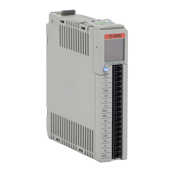
Page 208: P2-04Da Analog Output
Chapter 3: Analog I/O Specifications P2-04DA Analog Output The P2-04DA Voltage/Current Analog Output Module provides four channels of ±10VDC or 4–20 mA sinking/sourcing selectable outputs. Output Specifications Output Channels 1) ±10VDC Module Signal Output Ranges 2) 4–20mA (sinking or sourcing per channel) 16-bit Signal Resolution 1+0.100V... - Page 209 Chapter 3: Analog I/O Specifications P2-04DA Analog Output (continued) General Specifications Operating Temperature 0º to 60ºC (32º to 140ºF) -20º to 70ºC (-4º to 158ºF) Storage Temperature Humidity 5 to 95% (non-condensing) Environmental Air No corrosive gases permitted Vibration IEC60068-2-6 (Test Fc) Shock IEC60068-2-27 (Test Ea) 1800VAC applied for 1 second...
-
Page 210: Wiring Diagrams
Chapter 3: Analog I/O Specifications P2-04DA Analog Output (continued) Wiring Diagrams INTERNAL MODULE CIRCUITRY 24VDC+ voltage sink/source 4-20 mA current sinking 4-20 mA current sourcing voltage sink/source 4-20 mA current sinking 4-20 mA current sourcing 24VDC+ 24 VDC User 24VDC- Supplied Power voltage sink/source 4-20 mA current sinking... - Page 211 Chapter 3: Analog I/O Specifications P2-04DA Analog Output (continued) Wiring Diagrams (continued) Voltage Output Current Source Output (Field device is sinking) 0 - 10 4 - 20mA VDC Load Load 24 VDC User AC or DC Supplied Power 4-wire 4 - 20mA Load ±10 VDC Load AC or DC...
-
Page 212: Configuration Settings
Chapter 3: Analog I/O Specifications P2-04DA Analog Output (continued) Configuration Settings Using the Hardware Configuration tool in the Productivity Suite programming software, drag and drop the P2-04DA module into the base configuration. Select Automatic Module Verification or No Verification and Enable Hot Swap. If desired, assign a User Tagname to each output point (channel) selected and to each Status Bit Item. -
Page 213: Oled Panel Display
Chapter 3: Analog I/O Specifications P2-04DA Analog Output (continued) OLED Panel Display Power On Hold SEL button down to cycle through primary screens. Release button to select screen. DISPLAY DISPLAY DISPLAY DISPLAY DISPLAY PASSED Appears UNITS UNITS UNITS SETUP STATUS initially SELF DECIMAL... -
Page 214: P2-04Dal-1 Analog Output
Chapter 3: Analog I/O Specifications P2-04DAL-1 Analog Output The P2-04DAL-1 Low Resolution Current Output Module provides four channels for converting a digital value of 0 to 4095 (12-bit) to 4–20 mA analog signals for use with the Productivity 2000 System. ®... - Page 215 Chapter 3: Analog I/O Specifications P2-04DAL-1 Analog Output (continued) General Specifications Operating Temperature 0º to 60ºC (32º to 140ºF) -20º to 70ºC (-4º to 158ºF) Storage Temperature Humidity 5 to 95% (non-condensing) Environmental Air No corrosive gases permitted Vibration IEC60068-2-6 (Test Fc) Shock IEC60068-2-27 (Test Ea) 1800VAC applied for 1 second...
-
Page 216: Wiring Diagrams
Chapter 3: Analog I/O Specifications P2-04DAL-1 Analog Output (continued) Wiring Diagrams INTERNAL MODULE CIRCUITRY 4-20 mA current sourcing CH1 ADC 4-20 mA current sourcing CH2 ADC 4-20 mA current sourcing CH3 ADC 4-20 mA current sourcing CH4 ADC ISOLATED ANALOG CIRCUIT POWER 24VDC User SuppliedPower... -
Page 217: Configuration Settings
Chapter 3: Analog I/O Specifications P2-04DAL-1 Analog Output (continued) Configuration Settings Using the Hardware Configuration tool in the Productivity Suite programming software, drag and drop the P2-04DAL-1 module into the base configuration. Select Automatic Module Verification or No Verification and Enable Hot Swap. If desired, assign a User Tagname to each output point (channel) selected and to each Status Bit Item. -
Page 218: P2-04Dal-2 Analog Output
Chapter 3: Analog I/O Specifications P2-04DAL-2 Analog Output The P2-04DAL-2 Low Resolution Voltage Output Module provides four channels for converting a digital value of 0 to 4095 (12-bit) to 0–10 VDC analog signals for use with the Productivity 2000 System. ®... - Page 219 Chapter 3: Analog I/O Specifications P2-04DAL-2 Analog Output (continued) General Specifications 0º to 60ºC (32º to 140ºF) Operating Temperature Storage Temperature -20º to 70ºC (-4º to 158ºF) Humidity 5 to 95% (non-condensing) No corrosive gases permitted Environmental Air Vibration IEC60068-2-6 (Test Fc) IEC60068-2-27 (Test Ea) Shock Field to Logic Side Isolation...
-
Page 220: Wiring Diagrams
Chapter 3: Analog I/O Specifications P2-04DAL-2 Analog Output (continued) Wiring Diagrams INTERNAL MODULE CIRCUITRY voltage source CH1 DAC voltage source CH2 DAC voltage source CH3 DAC voltage source CH4 DAC 24V+ ISOLATED ANALOG CIRCUIT POWER 24VDC User SuppliedPower ISOLATED ANALOG CIRCUIT COMMON Voltage Output Circuits Voltage Output Circuits... -
Page 221: Configuration Settings
Chapter 3: Analog I/O Specifications P2-04DAL-2 Analog Output (continued) Configuration Settings Using the Hardware Configuration tool in the Productivity Suite programming software, drag and drop the P2-04DAL-2 module into the base configuration. Select Automatic Module Verification or No Verification and Enable Hot Swap. If desired, assign a User Tagname to each output point (channel) selected and to each Status Bit Item. -
Page 222: P2-08Da-1 Current Analog Output
Chapter 3: Analog I/O Specifications P2-08DA-1 Current Analog Output The P2-08DA-1 Current Analog Output Module provides eight channels of 4 to 20mA outputs. Output Specifications Output Channels (Commons) 4–20mA Module Signal Output Range 16-bit Output Signal Resolution 1 18.23 4–20mA = 0.244 μA/count 2 14.23 Resolution Value of LSB 4.00... - Page 223 Chapter 3: Analog I/O Specifications P2-08DA-1 Current Analog Output (continued) General Specifications Operating Temperature 0º to 60ºC (32º to 140ºF) -20º to 70ºC (-4º to 158ºF) Storage Temperature Humidity 5 to 95% (non-condensing) Environmental Air No corrosive gases permitted Vibration IEC60068-2-6 (Test Fc) Shock IEC60068-2-27 (Test Ea)
-
Page 224: Wiring Diagrams
Chapter 3: Analog I/O Specifications P2-08DA-1 Current Analog Output (continued) Wiring Diagrams INTERNAL MODULE CIRCUITRY 4-20 mA current sourcing CH1 ADC 4-20 mA current sourcing CH2 ADC 4-20 mA current sourcing CH3 ADC 4-20 mA current sourcing CH4 ADC 4-20 mA current sourcing CH5 ADC 4-20 mA current sourcing CH6 ADC... -
Page 225: Module Configuration
Chapter 3: Analog I/O Specifications P2-08DA-1 Current Analog Output (continued) Module Configuration Using the Hardware Configuration tool in the Productivity Suite programming software, drag and drop the P2-08DA-1 module into the base configuration. Select Automatic Module Verification or No Verification and Enable Hot Swap. If desired, assign a User Tagname to each output point (channel) selected and to each Status Bit Item. - Page 226 Chapter 3: Analog I/O Specifications P2-08DA-1 Current Analog Output (continued) OLED Panel Display Power On Hold SEL button down to cycle through primary screens. Release button to select screen. DISPLAY DISPLAY DISPLAY PASSED Appears DISPLAY DISPLAY initially UNITS UNITS UNITS SELF SETUP STATUS...
-
Page 227: P2-08Da-2 Voltage Analog Output
Chapter 3: Analog I/O Specifications P2-08DA-2 Voltage Analog Output The P2-08DA-2 Voltage Analog Output Module provides eight channels of ±10 VDC outputs for use with the Productivity 2000 Ssystem. ® Output Specifications Output Channels (Commons) ±10VDC Module Signal Output Range 16-bit Output Signal Resolution 1 1.823V... - Page 228 Chapter 3: Analog I/O Specifications P2-08DA-2 Voltage Analog Output (continued) General Specifications 0º to 60ºC (32º to 140ºF) Operating Temperature Storage Temperature -20º to 70ºC (-4º to 158ºF) 5 to 95% (non-condensing) Humidity Environmental Air No corrosive gases permitted Vibration IEC60068-2-6 (Test Fc) IEC60068-2-27 (Test Ea) Shock...
-
Page 229: Wiring Diagrams
Chapter 3: Analog I/O Specifications P2-08DA-2 Voltage Analog Output (continued) Wiring Diagrams INTERNAL MODULE CIRCUITRY voltage sink/source CH1 DAC voltage sink/source CH2 DAC voltage sink/source CH3 DAC voltage sink/source CH4 DAC voltage sink/source CH5 DAC voltage sink/source CH6 DAC voltage sink/source CH7 DAC voltage sink/source CH8 DAC... -
Page 230: Module Configuration
Chapter 3: Analog I/O Specifications P2-08DA-2 Voltage Analog Output (continued) Module Configuration Using the Hardware Configuration tool in the Productivity Suite programming software, drag and drop the P2-08DA-2 module into the base configuration. Select Automatic Module Verification or No Verification and Enable Hot Swap and Stop Mode Values. - Page 231 Chapter 3: Analog I/O Specifications P2-08DA-2 Voltage Analog Output (continued) OLED Panel Display Power On Hold SEL button down to cycle through primary screens. Release button to select screen. DISPLAY DISPLAY DISPLAY PASSED Appears DISPLAY DISPLAY initially UNITS UNITS UNITS SELF SETUP STATUS...
-
Page 232: P2-08Dal-1 Current Analog Output
Chapter 3: Analog I/O Specifications P2-08DAL-1 Current Analog Output The P2-08DAL-1 Low Resolution Current Analog Output Module provides eight channels of 4–20 mA output signals. Output Specifications Output Channels Module Signal Output Range 4–20mA Signal Resolution 12-bit Resolution Value of LSB 4–20mA = 3.9 μA / count (least significant bit) 1 LSB = 1 count... - Page 233 Chapter 3: Analog I/O Specifications P2-08DAL-1 Current Analog Output (continued) General Specifications Operating Temperature 0º to 60ºC (32º to 140ºF) Storage Temperature -20º to 70ºC (-4º to 158ºF) Humidity 5 to 95% (non-condensing) Environmental Air No corrosive gases permitted Vibration IEC60068-2-6 (Test Fc) Shock IEC60068-2-27 (Test Ea)
-
Page 234: Wiring Diagrams
Chapter 3: Analog I/O Specifications P2-08DAL-1 Current Analog Output (continued) Wiring Diagrams INTERNAL MODULE CIRCUITRY 4-20mA current sourcing CH1 DAC 4-20mA current sourcing CH2 DAC 4-20mA current sourcing CH3 DAC 4-20mA current sourcing CH4 DAC 4-20mA current sourcing CH5 DAC 4-20mA current sourcing CH6 DAC 4-20mA current sourcing... -
Page 235: Module Configuration
Chapter 3: Analog I/O Specifications P2-08DAL-1 Current Analog Output (continued) Module Configuration Using the Hardware Configuration tool in the Productivity Suite programming software, drag and drop the P2-08DAL-1 module into the base configuration. Select Automatic Module Verification or No Verification and Enable Hot Swap. If desired, assign a User Tagname to each output point (channel selected and to each Status Bit Item. -
Page 236: P2-08Dal-2 Voltage Analog Output
Chapter 3: Analog I/O Specifications P2-08DAL-2 Voltage Analog Output The P2-08DAL-2 Low Resolution Voltage Analog Output Module provides eight channels of 0–10 VDC output signals. Output Specifications Output Channels Module Signal Input Range 0–10V Output Signal Resolution 12-bit Resolution Value of LSB 0–10V = 2.44 mV per count (least significant bit) 1 LSB = 1 count... - Page 237 Chapter 3: Analog I/O Specifications P2-08DAL-2 Voltage Analog Output (continued) General Specifications Operating Temperature 0º to 60ºC (32º to 140ºF) -20º to 70ºC (-4º to 158ºF) Storage Temperature Humidity 5 to 95% (non-condensing) Environmental Air No corrosive gases permitted Vibration IEC60068-2-6 (Test Fc) Shock IEC60068-2-27 (Test Ea)
-
Page 238: Wiring Diagrams
Chapter 3: Analog I/O Specifications P2-08DAL-2 Voltage Analog Output (continued) Wiring Diagrams INTERNAL MODULE CIRCUITRY voltage sink/source CH1 DAC voltage sink/source CH2 DAC voltage sink/source CH3 DAC voltage sink/source CH4 DAC voltage sink/source CH5 DAC voltage sink/source CH6 DAC voltage sink/source CH7 DAC voltage sink/source CH8 DAC... -
Page 239: Module Configuration
Chapter 3: Analog I/O Specifications P2-08DAL-2 Voltage Analog Output (continued) Module Configuration Using the Hardware Configuration tool in the Productivity Suite programming software, drag and drop the P2-08DAL-2 module into the base configuration. Select Automatic Module Verification or No Verification and Enable Hot Swap. If desired, assign a User Tagname to each output point (channel selected and to each Status Bit Item. -
Page 240: P2-16Da-1 Current Analog Output
Chapter 3: Analog I/O Specifications P2-16DA-1 Current Analog Output The P2-16DA-1 Current Analog Output Module provides sixteen channels of 4–20 mA sourcing output. Output Specifications Output Channels 4–20mA (Sourcing) Module Signal Output Range 16-bit Output Signal Resolution 1 8 . 2 3 1 4 . - Page 241 Chapter 3: Analog I/O Specifications P2-16DA-1 Current Analog Output (continued) General Specifications Operating Temperature 0º to 60ºC (32º to 140ºF) Storage Temperature -20º to 70ºC (-4º to 158ºF) Humidity 5 to 95% (non-condensing) Environmental Air No corrosive gases permitted Vibration IEC60068-2-6 (Test Fc) Shock IEC60068-2-27 (Test Ea)
-
Page 242: Wiring Diagrams
Chapter 3: Analog I/O Specifications P2-16DA-1 Current Analog Output (continued) Wiring Diagrams INTERNAL MODULE CIRCUITRY CH1 ADC CH5 ADC CH2 ADC CH6 ADC CH3 ADC CH7 ADC CH4 ADC CH8 ADC CH9 ADC ISOLATED CH13 ADC ANALOG I13+ CH10 ADC I10+ CH14 ADC CIRCUIT... -
Page 243: Module Configuration
Chapter 3: Analog I/O Specifications P2-16DA-1 Current Analog Output (continued) Module Configuration Using the Hardware Configuration tool in the Productivity Suite programming software, drag and drop the P2-16DA-1 module into the base configuration. Select Automatic Module Verification or No Verification and Enable Hot Swap. If desired, assign a User Tagname to each output point (channel) selected and to each Status Bit Item. -
Page 244: Oled Panel Display
Chapter 3: Analog I/O Specifications P2-16DA-1 Current Analog Output (continued) OLED Panel Display Power On Hold SEL button down to cycle through primary screens. Release button to select screen. DISPLAY DISPLAY DISPLAY PASSED Appears DISPLAY DISPLAY initially UNITS UNITS UNITS SELF SETUP STATUS... -
Page 245: P2-16Da-2 Voltage Analog Output
Chapter 3: Analog I/O Specifications P2-16DA-2 Voltage Analog Output The P2-16DA-2 Voltage Analog Output Module provides sixteen channels of ±10VDC outputs. Output Specifications Output Channels 1 + 1 . 8 2 3 V ±10VDC Module Signal Output Range 2 + 1 . 4 2 3 V 3 –... - Page 246 Chapter 3: Analog I/O Specifications P2-16DA-2 Voltage Analog Output (continued) General Specifications Operating Temperature 0º to 60ºC (32º to 140ºF) -20º to 70ºC (-4º to 158ºF) Storage Temperature 5 to 95% (non-condensing) Humidity Environmental Air No corrosive gases permitted Vibration IEC60068-2-6 (Test Fc) IEC60068-2-27 (Test Ea) Shock...
-
Page 247: Wiring Diagrams
Chapter 3: Analog I/O Specifications P2-16DA-2 Voltage Analog Output (continued) Wiring Diagrams INTERNAL MODULE CIRCUITRY CH1 ADC CH5 ADC CH2 ADC CH6 ADC CH3 ADC CH7 ADC CH4 ADC CH8 ADC 24VDC+/-10% CH9 ADC ISOLATED CH13 ADC V13+ ANALOG CH10 ADC V10+ CH14 ADC CIRCUIT... -
Page 248: Module Configuration
Chapter 3: Analog I/O Specifications P2-16DA-2 Voltage Analog Output (continued) Module Configuration Using the Hardware Configuration tool in the Productivity Suite programming software, drag and drop the P2-16DA-2 module into the base configuration. Select Automatic Module Verification or No Verification and Enable Hot Swap. If desired, assign a User Tagname to each output point (channel) selected and to each Status Bit Item. -
Page 249: Lcd Panel Display
Chapter 3: Analog I/O Specifications P2-16DA-2 Voltage Analog Output (continued) LCD Panel Display Power On Hold SEL button down to cycle through primary screens. Release button to select screen. DISPLAY DISPLAY PASSED DISPLAY DISPLAY DISPLAY Appears initially UNITS UNITS SELF SETUP STATUS UNITS... -
Page 250: P2-16Dal-1 Current Analog Output
Chapter 3: Analog I/O Specifications P2-16DAL-1 Current Analog Output The P2-16DAL-1 Low Resolution Current Analog Output Module provides sixteen channels of 4–20mA sourcing output signals for use with Productivity 2000 system. ® Output Specifications Output Channels Module Signal Output Range 4–20mA Sourcing Signal Resolution 12-bit... - Page 251 Chapter 3: Analog I/O Specifications P2-16DAL-1 Current Analog Output (continued) General Specifications Operating Temperature 0º to 60ºC (32º to 140ºF) Storage Temperature -20º to 70ºC (-4º to 158ºF) Humidity 5 to 95% (non-condensing) Environmental Air No corrosive gases permitted Vibration IEC60068-2-6 (Test Fc) Shock IEC60068-2-27 (Test Ea)
-
Page 252: Wiring Diagrams
Chapter 3: Analog I/O Specifications P2-16DAL-1 Current Analog Output (continued) Wiring Diagrams INTERNAL MODULE CIRCUITRY CH1 ADC CH5 ADC CH2 ADC CH6 ADC CH3 ADC CH7 ADC CH4 ADC CH8 ADC CH9 ADC ISOLATED CH13 ADC ANALOG I13+ CH10 ADC I10+ CH14 ADC CIRCUIT... -
Page 253: Module Configuration
Chapter 3: Analog I/O Specifications P2-16DAL-1 Current Analog Output (continued) Module Configuration Using the Hardware Configuration tool in the Productivity Suite programming software, drag and drop the P2-16DAL-1 module into the base configuration. Select Automatic Module Verification or No Verification and Enable Hot Swap. If desired, assign a User Tagname to each output point (channel selected and to each Status Bit Item. -
Page 254: P2-16Dal-2 Voltage Analog Output
Chapter 3: Analog I/O Specifications P2-16DAL-2 Voltage Analog Output The P2-16DAL-2 Low Resolution Voltage Analog Output Module provides sixteen channels of 0–10 VDC outputs for use with Productivity 2000 system. ® Output Specifications Output Channels Module Signal Input Range 0–10V Output Signal Resolution 12-bit Resolution Value of LSB... - Page 255 Chapter 3: Analog I/O Specifications P2-16DAL-2 Voltage Analog Output (continued) General Specifications Surrounding Temperature 0º to 60ºC (32º to 140ºF) Storage Temperature -20º to 70ºC (-4º to 158ºF) Humidity 5 to 95% (non-condensing) Environmental Air No corrosive gases permitted Vibration IEC60068-2-6 (Test Fc) Shock IEC60068-2-27 (Test Ea)
-
Page 256: Wiring Diagrams
Chapter 3: Analog I/O Specifications P2-16DAL-2 Voltage Analog Output (continued) Wiring Diagrams INTERNAL MODULE INTERNAL CIRCUITRY MODULE CIRCUITRY CH1 ADC CH1 ADC CH5 ADC CH5 ADC CH2 ADC CH2 ADC CH6 ADC CH6 ADC CH3 ADC CH3 ADC CH7 ADC CH7 ADC CH4 ADC CH4 ADC... -
Page 257: Module Configuration
Chapter 3: Analog I/O Specifications P2-16DAL-2 Voltage Analog Output (continued) Module Configuration Using the Hardware Configuration tool in the Productivity Suite programming software, drag and drop the P2-16DAL-2 module into the base configuration. Select Automatic Module Verification or No Verification and Enable Hot Swap. If desired, assign a User Tagname to each input point (channel) selected and to each Status Bit Item. -
Page 258: P2-8Ad4Da-1 Current Analog Input/Output
Chapter 3: Analog I/O Specifications P2-8AD4DA-1 Current Analog Input/Output The P2-8AD4DA-1 Current Analog Input/Output Module provides eight channels of current sinking 0–20 mA inputs and four channels of current sourcing 4–20 mA outputs. Input Specifications 8 (1 common) Input Channels 1I00.00 0–20mA (Sinking) Module Signal Input Range... - Page 259 Chapter 3: Analog I/O Specifications P2-8AD4DA-1 Current Analog Input/Output (continued) Output Specifications Output Channels 4 (1 common) Module Signal Output Range 4–20mA Sourcing Output Signal Resolution 16-bit Resolution Value of LSB 0.244 μA / count (least significant bit) 1 LSB = 1 count Data Range 0–65535 counts Output Type...
- Page 260 Chapter 3: Analog I/O Specifications P2-8AD4DA-1 Current Analog Input/Output (continued) General Specifications Operating Temperature 0º to 60ºC (32º to 140ºF) Storage Temperature -20º to 70ºC (-4º to 158ºF) 5 to 95% (non-condensing) Humidity Environmental Air No corrosive gases permitted IEC60068-2-6 (Test Fc) Vibration Shock IEC60068-2-27 (Test Ea)
-
Page 261: Wiring Diagrams
Chapter 3: Analog I/O Specifications P2-8AD4DA-1 Current Analog Input/Output (continued) Wiring Diagrams Current Input Circuits An Edison S500-32-R – 0.032 A fast-acting fuse fuse is recommended for all .032A 2-Wire 4-20 mA 4-20 mA current loops. Transmitter – +24VDC User 2-Wire Transmitter Supplied Power fuse... -
Page 262: Module Configuration
Chapter 3: Analog I/O Specifications P2-8AD4DA-1 Current Analog Input/Output (continued) Module Configuration Using the Hardware Configuration tool in the Productivity Suite programming software, drag and drop the P2-8AD4DA-1 module into the base configuration. Select Automatic Module Verification or No Verification and Enable Hot Swap. -
Page 263: Oled Panel Display
Chapter 3: Analog I/O Specifications P2-8AD4DA-1 Current Analog Input/Output (continued) OLED Panel Display Hold SEL button down to cycle through primary screens. Release button to select screen. Power On Appears PASSED DISPLAY DISPLAY DISPLAY DISPLAY DISPLAY initially SELF SETUP STATUS UNITS UNITS UNITS... -
Page 264: P2-8Ad4Da-2 Voltage Analog Input/Output
Chapter 3: Analog I/O Specifications P2-8AD4DA-2 Voltage Analog Input/Output The P2-8AD4DA-2 Voltage Analog Input/Output Module provides eight channels of 0–10 VDC inputs and four channels of 0–10 VDC outputs. Input Specifications Input Channels 8 inputs (1 common) Input Ranges 0–5 VDC, 0–10 VDC 1I00.00V 2I00.00V Signal Resolution... - Page 265 Chapter 3: Analog I/O Specifications P2-8AD4DA-2 Voltage Analog Input/Output (continued) Output Specifications 4 (1 common) Output Channels 0–10 VDC, 0–5 VDC Module Signal Output Range 16-bit Output Signal Resolution 0–5V = 76μV/count Resolution Value of LSB 0–10V = 152μV/count (least significant bit) 1 LSB = 1 count 0–65535 counts Data Range...
- Page 266 Chapter 3: Analog I/O Specifications P2-8AD4DA-2 Voltage Analog Input/Output (continued) General Specifications Operating Temperature 0º to 60ºC (32º to 140ºF) -20º to 70ºC (-4º to 158ºF) Storage Temperature Humidity 5 to 95% (non-condensing) Environmental Air No corrosive gases permitted Vibration IEC60068-2-6 (Test Fc) Shock IEC60068-2-27 (Test Ea)
-
Page 267: Wiring Diagrams
Chapter 3: Analog I/O Specifications P2-8AD4DA-2 Voltage Analog Input/Output (continued) Wiring Diagrams INTERNAL MODULE CIRCUITRY CH1 ADC CH2 ADC CH3 ADC CH4 ADC CH5 ADC CH6 ADC Voltage Input Circuits CH7 ADC CH8 ADC 4-Wire Voltage Transmitter CH1 DAC Transmitter AC or DC CH2 DAC Power Supply... -
Page 268: Module Configuration
Chapter 3: Analog I/O Specifications P2-8AD4DA-2 Voltage Analog Input/Output (continued) Module Configuration Using the Hardware Configuration tool in the Productivity Suite programming software, drag and drop the P2-8AD4DA-2 module into the base configuration. Select Automatic Module Verification or No Verification and Enable Hot Swap. - Page 269 Chapter 3: Analog I/O Specifications P2-8AD4DA-2 Voltage Analog Input/Output (continued) OLED Panel Display Power On Hold SEL button down to cycle through primary screens. Release button to select screen. Appears PASSED DISPLAY DISPLAY DISPLAY DISPLAY DISPLAY initially SELF SETUP STATUS UNITS UNITS UNITS...
- Page 270 hapter hapter hapter pecialty odule pecificationS In This Chapter... P2-HSI High-Speed Input Module Overview ............4–2 HSI LED Indicators ....................4–3 HSI Input Specifications .................... 4–4 HSI Status Output Specifications ................4–6 Frequency Response ....................4–6 HSI Wiring Examples ....................4–8 P2-HSO High-Speed Output Module Overview ............
-
Page 271: P2-Hsi High-Speed Input Module Overview
Chapter 4: Specialty Module Specifications P2-HSI High-Speed Input Module Overview The P2-HSI High-Speed (1MHz) Input Module provides differential (line receiver, 5V max) and single ended (5-24V) inputs that accept up to 1MHz of pulse/direction and quadrature signals on each of the two independent input channels. Additionally, four 5-24 VDC general purpose high-speed inputs and four general purpose, 5-24 VDC 0.5 amp, outputs are included for use with any Productivity 2000 system. -
Page 272: Hsi Led Indicators
Chapter 4: Specialty Module Specifications P2-HSI High-Speed Input Module (continued) HSI LED Indicators Status LEDs (F) 1, 2, 3 & 4 (one per status output) Fault Status LEDs (IN) 1A, 1B, 1Z, 2A, 2B, 2Z, IN3 & IN4 (one per Input LEDs status input) Output Status... -
Page 273: Hsi Input Specifications
Chapter 4: Specialty Module Specifications P2-HSI High-Speed Input Module (continued) HSI Input Specifications Differential (5V) Input Specifications Differential inputs (6 pts: 1A, 1B, 1Z, 2A, Pulse Inputs* 2B, 2Z) Isolation Each input is isolated from other circuits Input Signal Type, per Channel Differential Select 5VDC... - Page 274 Chapter 4: Specialty Module Specifications P2-HSI High-Speed Input Module (continued) HSI Input Specifications Single Ended (5-24V) Input Specifications Single ended inputs (8 pts: 1A, 1B, 1Z, Status Input 2A, 2B, 2Z, 3IN, 4IN) Isolation Each input is isolated from other circuits Input Volts Range 5–24 VDC Input Volts Maximum...
-
Page 275: Hsi Status Output Specifications
Chapter 4: Specialty Module Specifications P2-HSI High-Speed Input Module (continued) HSI Status Output Specifications Status Output Specifications Status Outputs 4 sink/source Output Signal Type, per Channel Current Sinking Current Sourcing Select Operating Voltage¹ 5–24 VDC 5–24 VDC¹ Output Volts Maximum 36VDC 26.4 VDC¹... - Page 276 Chapter 4: Specialty Module Specifications P2-HSI High-Speed Input Module (continued) Frequency Response Inaccuracy of Frequency Measurements¹,² for “Slow Mode” Input Frequency Step/Dir Quadrature 1X Quadrature 4X ±0.002 Hz ±0.002 Hz ±0.002 Hz 10Hz ±0.009 Hz ±0.009 Hz ±0.009 Hz 100Hz ±0.015 Hz ±0.015 Hz ±0.015 Hz...
-
Page 277: Hsi Wiring Examples
Chapter 4: Specialty Module Specifications P2-HSI High-Speed Input Module (continued) HSI Wiring Examples Status Inputs Wiring Diagram P2-HSI 5VDC to 24VDC 2K Ohm IN3+ Sourcing Field Device IN3- 2K Ohm Sensor IN4+ IN4- 2K Ohm Sinking Field Device 2K Ohm Sensor Status Outputs Wiring Diagram P2-HSI... - Page 278 Chapter 4: Specialty Module Specifications P2-HSI High-Speed Input Module (continued) 5V Encoder Inputs Wiring Diagram To prevent damage to P2-HSI 5V inputs, do not exceed 6.8V or 30 mA on inputs 1A, 1A, 1B, 1B, 1Z, 1Z, 2A, 2A, 2B, 2B, 2Z, & 2Z. Encoder with 5V P2-HSI Line Drivers...
- Page 279 Chapter 4: Specialty Module Specifications P2-HSI High-Speed Input Module (continued) Sinking I/O Wiring Diagram Do not exceed 6.8V on these inputs OUT1 OUT1 OUT2 OUT2 OUT3 OUT3 OUT4 OUT4 -1A +1A -1B +1B -1Z +1Z -2A +2A -2B +2B -2Z +2Z Panel GND.
-
Page 280: P2-Hso High-Speed Output Module Overview
Chapter 4: Specialty Module Specifications P2-HSO High-Speed Output Module Overview The P2-HSO High-Speed Output Module provides up to of (1MHz) pulse/direction, up/ down and quadrature pulse output on each of two independent output channels. Additionally, six 5-24 VDC general purpose inputs and four 5-24 VDC general purpose outputs are included for use with the Productivity 2000 System. -
Page 281: Hsi Led Indicators
Chapter 4: Specialty Module Specifications P2-HSO High-Speed Output Module (continued) HSI LED Indicators Status LEDs (F) 1, 2, 3, 4, 5, 6 (one per pulse output and one per Fault Status LEDs status output) Input LEDs (IN) 1, 2, 3, 4, 5, 6 (one per status input) Output Status LEDs (O) OUT 1A &... -
Page 282: Hsi Output Specifications
Chapter 4: Specialty Module Specifications P2-HSO High-Speed Output Module (continued) HSI Output Specifications Pulse Output Specifications 2 Channels Pulse Outputs Output Pulse Type, per Channel Selectable for pulse & direction, up/down or Select quadrature RS-422 Line Driver Open Drain FET Output Signal Type, per Channel Current Sinking Outputs... - Page 283 Chapter 4: Specialty Module Specifications P2-HSO High-Speed Output Module (continued) Status Output Specifications Status Outputs 4 sink/source Output Signal Type, per Channel Current Sinking Current Sourcing Select ² Operating Voltage² 5–24 VDC 5–24 VDC ² Output Volts Maximum² 36VDC 26.4 VDC Output Current Maximum 500mA Overcurrent Protection...
-
Page 284: Hso Wiring Examples
Chapter 4: Specialty Module Specifications P2-HSO High-Speed Output Module (continued) HSO Wiring Examples Status Inputs and Outputs P2-HSO Inputs 5VDC to 24VDC IN1+ Sourcing Field Device IN1- IN2+ Sensor IN2- IN3+ Sinking Field Device IN3- IN4+ Sensor IN4- IN5+ IN5- IN6+ IN6- P2-HSO... - Page 285 Chapter 4: Specialty Module Specifications P2-HSO High-Speed Output Module (continued) Sinking Pulse Output Wiring Diagram P2-HSO Stepper Amp #1 1A SNK PULSE - OPTO PWR 1B SNK DIR - SHLD Belden 3105A shielded, twisted pair, low capacitance. Stepper Amp #2 2A SNK PULSE - OPTO PWR...
- Page 286 Chapter 4: Specialty Module Specifications P2-HSO High-Speed Output Module (continued) SureServo Wiring Diagram P2-HSO SureServo Drive Belden 3105A shielded, twisted pair, low capacitance. PULL HI /PULSE 1A SNK PULSE COM– 1B SNK /SIGN SIGN COM– SHLD Tie shield to panel ground this end.
- Page 287 Chapter 4: Specialty Module Specifications P2-HSO High-Speed Output Module (continued) Sinking I/O Wiring Diagram OUT3 OUT3 OUT4 OUT4 OUT5 OUT5 1A 1A SH SH OUT6 OUT6 2A 2A 2B 2B Panel OUT3 OUT4 OUT6 GND. IN1+ IN2+ OUT5 24VDC 5VDC IN3+ IN4+ IN5+...
- Page 288 Chapter 4: Specialty Module Specifications P2-HSO High-Speed Output Module (continued) Sourcing I/O Wiring Diagram OUT3 OUT3 OUT4 OUT4 OUT5 OUT5 OUT6 OUT6 Panel GND. IN2- OUT3 OUT4 OUT5 OUT6 IN1- IN3- IN4- IN5- IN6- 24VDC 5VDC 24VDC Productivity 4–19 Hardware User Manual, 2nd Edition 2000...
-
Page 289: High-Speed Module Tester Utility
Chapter 4: Specialty Module Specifications High-Speed Module Tester Utility The High-Speed Module Tester is a software utility that allows a user to test the P2-HSO module’s inputs and outputs. It is highly recommended that you simulate your P2-HSO functions before attempting to control the module from your CPU program. -
Page 290: P2-Scm Module Overview
Chapter 4: Specialty Module Specifications P2-SCM Module Overview The P2-SCM Serial Communications Module provides three RS-232 ports and one RS-485 port for Modbus master/slave networking or connection to serial devices using ASCII or custom communication protocols. General Specifications Module Type Intelligent Modules per Base 15 maximum (See Note) -
Page 291: Scm Led Indicators
Chapter 4: Specialty Module Specifications P2-SCM Specifications, (continued) SCM LED Indicators STATUS DISPLAY - 14 LEDS - Shows communication status for each port PORT 1 - RS-232 - Provides 210mA 5V power for C-More Micro PORT 2 - RS-232 PORT 3 - RS-232 PORT 4 - RS-485... -
Page 292: P2-Scm Module Communications
Chapter 4: Specialty Module Specifications P2-SCM Module Communications RS-232 Serial Ports RS-232 Ports 1, 2 & 3 Electrical Specifications Units Output ON, Space Condition Volts (3kΩ, 1000pF Load) Output OFF, Mark Condition -5.2 -5.0 Volts (3kΩ, 1000pF Load) Output Short-Circuit Current Short-Circuit Duration Seconds Limit... -
Page 293: Serial Port 1
Chapter 4: Specialty Module Specifications P2-SCM Module Communications (continued) RS-232 Serial Port 1 Non-isolated RS-232 DTE port connects the CPU as a MODBUS/ASCII master or slave to a peripheral device. Includes ESD and built-in surge protection Port 1 Port Type RS-232 Non-isolated RS-232 DTE port connects the CPU as a Modbus/ASCII master or slave to a... -
Page 294: Serial Port 2 And 3
Chapter 4: Specialty Module Specifications P2-SCM Module Communications (continued) RS-232 Serial Port 2 and 3 Non-isolated RS-232 DTE port connects the CPU as a MODBUS/ASCII master or slave to a peripheral device. Port 2 and 3 RS-232 Port Type Non-isolated RS-232 DTE port connects the CPU as a Modbus/ASCII master or slave to a peripheral device. -
Page 295: Port 4
Chapter 4: Specialty Module Specifications P2-SCM Module Communications (continued) RS-485 Port 4 Non-isolated RS-485 port connects the CPU as a MODBUS/ASCII master or slave to a peripheral device(s). Port 4 Electrical Specifications Units Driver Differential Output (54Ω Volts Load) Driver Common-Mode Output Volts Driver Short-Circuit Output Current... - Page 296 Chapter 4: Specialty Module Specifications P2-SCM Module Communications (continued) RS-485 Port 4 Port 4 Port Type RS-485 Non-isolated RS-485 port connects the CPU as a Modbus/ASCII master or slave to Description a peripheral device. Includes ESD/EFT protection and automatic echo cancellation when transmitter is active.
- Page 297 hapter hapter hapter nstallatIon and IrIng In This Chapter... Safety Guidelines ....................... 5–3 Introduction ....................... 5–6 Dimensions and Installation ..................5–7 Mounting Guidelines ....................5–8 Wiring Guidelines ....................5–15 I/O Module Wiring Options ..................5–17 System Wiring Strategies ..................5–23...
-
Page 298: Chapter 5: Installation And Wiring
The protection provided by the equipment may be impaired if this equipment is used in a manner not specified in this manual. A listing of our international affiliates is available on our Web site at http://www.automationdirect.com. WARNING: Providing a safe operating environment for personnel and equipment is your responsibility and should be your primary goal during system planning and installation. -
Page 299: Three Levels Of Protection
Chapter 5: Installation and Wiring Three Levels of Protection WARNING: The control program must not be the only form of protection for any problems that may result in a risk of personal injury or equipment damage. The publications mentioned provide many ideas and requirements for system safety. -
Page 300: Emergency Stop Circuits
Chapter 5: Installation and Wiring Emergency Stop Circuits Emergency stop (E-Stop) circuits are a critical part of automation safety. For each machine controlled by a CPU, provide an emergency stop device that is wired outside the CPU and easily accessed by the machine operator. E-stop devices are commonly wired through a master control relay (MCR) or a safety control relay (SCR) that will remove power from the CPU I/O system in an emergency. -
Page 301: Introduction
Chapter 5: Installation and Wiring Introduction Productivity 2000 Mechanical Design ® The Productivity2000 is a modular system that requires a base to accommodate the various modules. Bases are available with 4, 7, 11 and 15 I/O module slots. The bases contain additional dedicated slots for the power supply and the CPU. -
Page 302: Dimensions And Installation
Make sure you have followed the installation guidelines for proper spacing. NOTE: Dimensional drawings for the CPU, power supply and all modules are available on the AutomationDirect.com site. Base Dimensions, inches [mm] 4.37 7.54... -
Page 303: Mounting Guidelines
Chapter 5: Installation and Wiring Mounting Guidelines Enclosures Your selection of a proper enclosure is important to ensure safe and proper operation of your Productivity 2000 system. Applications for the Productivity2000 system vary and may require ® additional hardware considerations. The minimum considerations for enclosures include: •... -
Page 304: Panel Layout
Chapter 5: Installation and Wiring Panel Layout 2” 50mm 3” 7.2” 76mm 183mm 3” 76mm 2” 50mm Ground Braid Copper Lugs Panel or AIRFLOW Single Point Ground Panel 2” 2” NOTE: Add 2" to mounting NOTE: Add depth when using ZIPLink depth when cable. -
Page 305: Other Specifications
Chapter 5: Installation and Wiring Other Specifications In addition to the panel layout guidelines, other specifications can affect the installation of a CPU system. Always consider the following: • Environmental Specifications • Power Requirements • Agency Approvals • Enclosure Selection and Component Dimensions WARNING: Do not disconnect equipment unless power has been switched off or the area is known to be non–hazardous. -
Page 306: Using Mounting Rails
Chapter 5: Installation and Wiring Using Mounting Rails The Productivity 2000 bases can be secured to the cabinet using mounting rails. You should ® use rails that conform to DIN EN standard 50022. We offer a complete line of DIN rail, DINnectors and DIN rail mounted apparatus. -
Page 307: Installing The Power Supply
Chapter 5: Installation and Wiring Installing the Power Supply Step One: Locate the left most socket in the base. Step Two: Insert the Power Supply at a 30° angle into the notch located at the bottom of the base and rotate up until seated in socket. -
Page 308: Installing The Cpu
Chapter 5: Installation and Wiring Installing the CPU This installation procedure applies to the P2-550 CPU module assembled in any of the multi- slot bases. Step One: Unlock both locking tabs Step Two: Seat CPU on support platform and push towards base until circuit board is fully engaged into connector. -
Page 309: Installing The I/O Modules
Chapter 5: Installation and Wiring Installing the I/O Modules WARNING: Do not apply field power until the following steps are completed. See hot-swapping rotate procedure for exceptions. to seated position Step One: Align module catch with base slot and rotate module into connector. -
Page 310: Wiring Guidelines
Chapter 5: Installation and Wiring Wiring Guidelines Wiring to the Power Supply Connect the AC power source input wiring to the power supply as shown. The power supply terminals can accept up to 14AWG solid or stranded wire. Do not over-tighten the terminal screws;... -
Page 311: Fuse Protection
Chapter 5: Installation and Wiring Fuse Protection Some of the Input and Output I/O module circuits do not have internal fuses. In order to protect your modules, we suggest you add external fuses to your I/O wiring. A fast-blow fuse with a lower current rating than the I/O bank’s common current rating can be wired to each common;... -
Page 312: I/O Module Wiring Options
Chapter 5: Installation and Wiring I/O Module Wiring Options There are two available methods for wiring most I/O modules: The ZIPLink wiring system or hand wiring to the optional removable I/O module terminal blocks. NOTE: The high-density 16-point ANALOG I/O modules require the use of a Molex style connector wiring system. - Page 313 Chapter 5: Installation and Wiring Input and Output Modules ZIPLink Selections The following tables show the P2000 modules and the corresponding ZIPLink module to be used. Productivity2000 Discrete Output Module ZIPLink Selector I/O Module ZIPLink Output Module Part Cable Part # of Terms Component Module P2-08TD1S...
- Page 314 Chapter 5: Installation and Wiring Analog and Specialty Module ZIPLink Selections Productivity2000 Discrete Input Module ZIPLink Selector I/O Module ZIPLink Input Module # of Terms Component Module Part Cable Part P2-08ND3-1 P2-08NE3 Feedthrough ZL-RTB20 ZL-P2-CBL18 * P2-16ND3-1 Feedthrough ZL-RTB20 P2-16NE3 ZL-P2-CBL18 * Sensor/LED ZL-LTB16-24...
- Page 315 Chapter 5: Installation and Wiring Analog and Specialty Module ZIPLink Selections Productivity2000 Analog Output Module ZIPLink Selector I/O Module ZIPLink Analog # of Terms Component Module Cable Module P2-04DA P2-04DAL-1 P2-04DAL-2 P2-08DA-1 Feedthrough ZL-RTB20 ZL-P2-CBL18 * P2-08DA-2 P2-08DAL-1 P2-08DAL-2 P2-16DA-1 P2-16DA-2 Feedthrough ZL-RTB20...
-
Page 316: Removable Terminal Blocks (Optional)
Chapter 5: Installation and Wiring Removable Terminal Blocks (Optional) The hand wiring method consists of purchasing the removable I/O module terminal block (part no. P2-RTB or P2-RTB-1) and hand wiring from the I/O terminal block to a DIN rail mounted terminal block. Removable Terminal Block P2-RTB Removable Terminal Block P2-RTB-1 Terminal Block Removal... -
Page 317: Planning The I/O Wiring Routes
Chapter 5: Installation and Wiring Planning the I/O Wiring Routes The following guidelines provide general information on how to wire the I/O connections to Productivity 2000 modules. For specific information on wiring a particular I/O module refer ® to the module specifications in Chapter 2. 1. -
Page 318: System Wiring Strategies
Chapter 5: Installation and Wiring System Wiring Strategies The Productivity 2000 system is very flexible and will work in many different wiring ® configurations. By studying this section before actual installation, you can find the best wiring strategy for your application. This will help to lower system cost and wiring errors, and avoid safety problems. -
Page 319: Sinking/Sourcing Concepts
Chapter 5: Installation and Wiring Sinking/Sourcing Concepts Before wiring field devices to the CPU I/O, it’s necessary to have a basic understanding of “sinking” and “sourcing” concepts. Use of these terms occurs frequently in input or output circuit discussions. The purpose of this section is to explain the terms. The short definitions are as follows: Sinking = Path to supply ground (–) or switching ground Sourcing = Path to supply source (+) or switching +V... -
Page 320: I/O "Common Terminal" Concepts
Chapter 5: Installation and Wiring I/O “Common Terminal” Concepts In order for a CPU I/O circuit to operate, current must enter at one terminal and exit at another. This means at least two terminals are associated with every I/O point. In the figure below, the input or output terminal is the main path for the current. -
Page 321: Dc Input Wiring Methods
Chapter 5: Installation and Wiring DC Input Wiring Methods I/O modules with DC inputs can be wired as either sinking or CPU DC Input sourcing inputs. The dual diodes (shown in this diagram) allow Input current to flow in either direction. Inputs grouped by a common point must be either all sinking or all sourcing. - Page 322 Chapter 5: Installation and Wiring CPU DC Sinking Output to Sinking Load Device In the example below, a sinking output point is connected to the sinking input of a field device load. In this case, both the CPU output and field device input are sinking type. Since the circuit must have one sourcing and one sinking device, we add sourcing capability to the CPU output by using a pull-up resistor.
-
Page 323: Relay Outputs - Wiring Methods
Chapter 5: Installation and Wiring Relay Outputs - Wiring Methods Relay outputs are available for the Productivity 2000. Relays are best for the following ® applications: • Loads that require higher currents than the solid-state outputs can deliver • Cost-sensitive applications •... -
Page 324: Relay Outputs - Transient Suppression For Inductive Loads In A Control System
Chapter 5: Installation and Wiring Relay Outputs – Transient Suppression for Inductive Loads in a Control System The following pages are intended to give a quick overview of the negative effects of transient voltages on a control system and provide some simple advice on how to effectively minimize them. - Page 325 Chapter 5: Installation and Wiring CPU’s Integrated Transient Suppressors Although the CPU outputs typically have integrated suppressors to protect against transients, they are not capable of handling them all. It is usually necessary to have some additional transient suppression for an inductive load. Here is another example using the same 24V/125mA/3W relay used earlier.
- Page 326 Chapter 5: Installation and Wiring Additional Transient Protection Types DC Coils: The most effective protection against transients from a DC coil is a flyback diode. A flyback diode can reduce the transient to roughly 1V over the supply voltage, as shown in this example. DC Flyback Circuit Volts Oscilloscope...
- Page 327 Chapter 5: Installation and Wiring Two more common options for DC coils are Metal Oxide Varistors (MOV) or TVS diodes. These devices should be connected across the driver (CPU output) for best protection as shown below. The optimum voltage rating for the suppressor is the lowest rated voltage available that will NOT conduct at the supply voltage, while allowing a safe margin.
- Page 328 hapter hapter hapter ommuniCations In This Chapter... Communications ......................6-1 Communication Ports ....................6-1 Communications: Connectivity ................. 6-8 P2-550 Port Connections ..................6-8 ASCII and Custom Protocol Functionality ............... 6-13 ASCII Instructions ....................6-13 Custom Protocol Instructions ................. 6-14 Communications: Ethernet ..................6-16 TCP and UDP Port Numbers ..................
- Page 329 Table of Contents Class 1 and Class 3 Connections ................6-37 Setup Example: Productivity 2000 as EtherNet/IP Adapter ........6-37 ® Setup Example: Productivity 2000 as EtherNet/IP Scanner ........6-40 ® Troubleshooting Tips: ..................... 6-43 EtherNet/IP I/O Message Troubleshooting: ............6-45 EtherNet/IP Explicit Message Troubleshooting: ............
-
Page 330: Chapter 6 - Communications
Chapter 6: Communications Communications Communication Ports The AutomationDirect Productivity 2000 CPU is provided P2-550 ® with several Communications Ports. A detailed description of each of these ports are described in the sections below. The Communication Ports are: General Specifications Item # Communication Port MicroSD Slot MicroUSB 2.0 Programming Port... - Page 331 Chapter 6: Communications P2-550 Communication Ports, (continued) 3. RS-232: The RS-232 port is an RJ-12 connector located on the lower right front of the CPU. This port can be used for: - Modbus RTU Master connections. - Modbus RTU Slave connections. - ASCII Incoming and Outgoing communications.
- Page 332 Chapter 6: Communications P2-550 Communication Ports, (continued) • ASCII Incoming and Outgoing communications: The RS-232 port can be used for sending and receiving non-sequenced String data. This feature is typically used for receiving bar code strings from a scanner or sending statistical data to a terminal or serial printer using the ASCII IN and ASCII OUT instructions.
- Page 333 Chapter 6: Communications P2-550 Communication Ports, (continued) 4. RS-485: The RS-485 port is a 3-pin removable terminal block. The RS-485 port can be used for: - Modbus RTU Master connections. - Modbus RTU Slave connections. - ASCII Incoming and Outgoing communications. - Custom Protocol Incoming and Outgoing communications.
- Page 334 Chapter 6: Communications P2-550 Communication Ports, (continued) • The Modbus RTU Slave connections: The RS-485 network port is used for multi-node networks. The port is addressable in the Hardware Configuration in the Productivity Suite programming software. If the port is set to Modbus RTU and there are no communications instructions (MRX, MWX, RX, WX) in the project, the CPU will automatically respond to Modbus requests from a Modbus master.
- Page 335 Chapter 6: Communications P2-550 Communication Ports, (continued) 5. External Ethernet: The Ethernet port is 10/100Base-T Ethernet with an RJ-45 style connector. It is used for: - Connection to a PC running the Productivity Suite programming software. - Modbus TCP Client connections (Modbus requests sent from the CPU). - Modbus TCP Server connections (Modbus requests received by the CPU).
- Page 336 Chapter 6: Communications P2-550 Communication Ports, (continued) NOTE: See Communications Port Configuration for port configuration; Communications Connectivity for connection information and Communications Ethernet for Ethernet set up. 6. Local Ethernet: This RJ45 Ethernet Port supports remote I/O. Located on the underside of the CPU, it is the rear port.
-
Page 337: Communications: Connectivity
Chapter 6: Communications Communications: Connectivity P2-550 Port Connections The AutomationDirect Procuctivity2000 P2-550 CPU is provided with six communications ports. The Connectivity for each of these ports is described in the following sections. The Communication Ports available are: 1. microSD Card Slot For program transfer and data logging (microSD card not included with processor). - Page 338 Chapter 6: Communications 3. RS-232 Port Serial RS-232 multipurpose communications port with RJ12 connector. The RS-232 Port can be connected to Modbus RTU master or slave devices, as well as devices that output non-sequenced ASCII strings or characters. The manner in which these devices are wired to the CPU depends whether the device is considered to be Data Terminal Equipment (DTE) or Data Communications Equipment (DCE).
- Page 339 Chapter 6: Communications 4. RS-485 Port • The RS-485 multipurpose serial communications port requires a removable 3-pin connector (See below). This port is useful for connecting multiple Modbus and ASCII devices on one network and/or connecting devices to the CPU at distances greater than 50 feet (RS-232 limit). The RS-485 standard supports distances of up to 1000 meters without requiring a repeater.
- Page 340 Chapter 6: Communications 5. External Ethernet Port • The 10/100 Base-T Ethernet port with RJ45 connector is used for programming and Modbus TCP Client/Server functions. Crossover Cable 10Base-T/100Base-TX OR/WHT GRN/WHT TD– TD– GRN/WHT OR/WHT BLU/WHT BLU/WHT RD– RD– BRN/WHT BRN/WHT RJ45 RJ45 General Information...
- Page 341 Chapter 6: Communications 5. External Ethernet Port, (continued) • Highlight the CPU that you wish to connect to and press the “Connect” button. You may see in the CPU Connections dialog box CPU’s that are not on the same subnet as your PC, but this does not mean you can connect to them.
-
Page 342: Ascii And Custom Protocol Functionality
Chapter 6: Communications 6. Local Ethernet Port, (continued) • The Local Ethernet Port is used to communicate to the GS Drives with a GS-EDRV100 Ethernet module. It is highly recommended that the network attached to this port be isolated from other networks and it is imperative that it be isolated from other Remote I/O networks. -
Page 343: Custom Protocol Instructions
Chapter 6: Communications ASCII and Custom Protocol Functionality, (continued) While the ASCII In instruction and the ASCII Out instruction can both be used in a project, they are not intended to be used in conjunction with one another. In other words, it is not advisable to use the ASCII Out instruction to send a String to a device that will respond (if the response is needed) and to use the ASCII In instruction to try to receive this data. - Page 344 Chapter 6: Communications ASCII and Custom Protocol Functionality, (continued) The Checksum option allows the user to select where in the packet the checksum should be inserted, what type of Checksum (CRC-8 bit, CRC-16 bit, CRC-32 bit, XOR-8 bit, XOR-16 bit and XOR 32 bit), which bytes of the data source should be used in the calculation of the checksum, what the byte order should be of the checksum (if greater than 8 bit) and how to preload the checksum calculation.
-
Page 345: Communications: Ethernet
Chapter 6: Communications Communications: Ethernet TCP and UDP Port Numbers When doing TCP/IP and UDP/IP communications, there is a Source Port number and Destination Port number for every message. The Client device must be aware of the Destination Port Number(s) the Server device is expecting to see and the Server device must listen for this Destination Port number. -
Page 346: Pc Setup
Chapter 6: Communications PC Setup For testing and verification purpose, it is recommended that the PC and the CPU be on an isolated Ethernet switch. Configure the PC’s network interface card setting as described below. Go to Start, then Run, type ncpa.cpl in the Open field and click on OK to bring up the Network Connections dialog. -
Page 347: Cpu Setup
Chapter 6: Communications PC Setup, (continued) 3. Internet Protocol (TCP/IP) Properties. In the Properties window, select Use the following IP address. Enter an IP Address of 192.168.1.1 and Subnet Mask 255.255.255.0 and select OK. Select OK again on the Local Area Connection Properties window. CPU Setup Now configure the CPU’s network IP setting as shown below. -
Page 348: Tcp Connection Behavior With Modbus Tcp And Network Instructions
Chapter 6: Communications CPU Setup, (continued) 3. The Change IP Address/CPU Name window will open as shown below. • Enter an IP Address of 192.168.1.2 and Subnet Mask 255.255.0.0 for the CPU’s network IP setting and select OK. The CPU is now configured with the correct IP Address for connectivity with the PC. The IP Address and Subnet Mask settings will very likely differ from what will be used in the actual application. -
Page 349: Communications Modbus Functionality
Chapter 6: Communications Communications Modbus Functionality Master/Client Function Code and Data Type Support The following table lists the Modbus data type, the function code and the CPU source data type that is supported when the CPU is the Client or Master on a Modbus TCP or serial connection. - Page 350 Chapter 6: Communications Modbus Client/Master Support (Using MRX and MWX Instructions) (continued) Modbus 984 Addressing Productivity 2000 Tag Types Function Modbus 984 ® Function Name Code Addressing (Zero Based) (Data designation or source) Integer 8 bit Unsigned (U8) Integer 16 bit (S16) Integer 16 bit Unsigned (U16) Integer 16 bit BCD (B16) Write Single...
-
Page 351: Slave/Server Function Code And Data Type Support
Chapter 6: Communications Slave/Server Function Code and Data Type Support The following table lists the Modbus data type, the function code and the CPU source data type that is supported when the CPU is the Server or Slave on a Modbus TCP or serial connection. Modbus Server/Slave Support Productivity 2000 Tag Types... -
Page 352: Assigning Modbus Addresses To Tags
Chapter 6: Communications Modbus Server/Slave Support (continued) Productivity 2000 Tag Types ® Function Code Function Name Modbus 984 Addressing (Data designation or source) Integer 8 bit Unsigned (U8) Integer 16 bit (S16) Integer 16 bit Unsigned (U16) Integer 16 bit BCD (B16) Integer 32 bit (S32) Write Multiple Registers 400001 - 465536... - Page 353 Chapter 6: Communications Assigning Modbus Addresses, (continued) • When this is done, two values will appear in the field The left most value is the Modbus data type. This is fixed based upon the tag data type. The chart below indicates the four different Modbus data types in the 984 addressing scheme.
- Page 354 Chapter 6: Communications Assigning Modbus Addresses, (continued) 2. Modbus mapping when creating Tags: • Modbus addresses can be assigned to Tags as they are created in the Tag Database. • Type in the Modbus offset value when entering the Tag Name and Data Type. •...
-
Page 355: Modbus Options
Chapter 6: Communications Modbus Options The Modbus protocol does not have a specific method outlined for data types outside of bits and 16-bit words. Most systems now have 32-bit data types. In order to transport 32-bit data types across Modbus, they must be placed into two Modbus 16-bit registers. Unfortunately, some devices do not support this method, so sometimes incompatibilities in the order in which the 16-bit high word and low word are handled between devices persist. - Page 356 Chapter 6: Communications Modbus Options, continued • Most Modbus Master/Client devices will attempt to optimize their data requests to a Modbus Slave/Server device by requesting blocks of data instead of individual registers. In the case mentioned previously, most Modbus masters would send one read request starting at 400001 and a size of three instead of sending two read requests starting at 400001 with size one and 400003 with size one as shown below.
- Page 357 Chapter 6: Communications Modbus Options, continued c. Map value to a single 16 bit Modbus register: • This option allows for compatibility with devices that do not support 32-bit Modbus functionality. This option can be selected individually for the Analog Input and Output Signed 32 data types and the Internal Signed 32 data types, including the array form of these data types.
-
Page 358: Modbus Instructions
Chapter 6: Communications Modbus Instructions To read or set data in other Modbus Slave/Server devices, there are two instructions available in the programming software, Modbus Read and Modbus Write. • The Modbus Read (MRX) instruction is used to read data from other Modbus devices into Tags of the CPU. - Page 359 Chapter 6: Communications Modbus Instructions, (continued) There is an “Automatic Polling” feature in the instruction to make it easier to read a device on a pre-determined poll rate. There is also a “poll offset” field that can be used when simultaneous instructions are enabled with the Automatic Polling feature to help stagger the flow of messages being sent to the network.
-
Page 360: Network Instructions
Chapter 6: Communications Network Instructions The Network Read (RX) and Network Write (WX) instructions are used to communicate to other CPU’s. They are very similar in operation to the MRX and MWX instructions but they target Tag Names instead of Modbus addresses in the other CPU. There is also a significant performance gain in using the RX and WX instructions when communicating to other CPU’s as opposed to using the MRX and MWX instructions. -
Page 361: Automatic Poll Versus Manual Polling And Interlocking
Chapter 6: Communications Network Instructions, (continued) The WX instruction operates in the same manner except that the data from the Local tags will be written into the Tags of the remote project. No Modbus mapping is required. NOTE: The PC programming software project for the Remote CPU must be accessible by the PC running the programming software for the Local project. - Page 362 Chapter 6: Communications Network Instructions, (continued) Read Request Flowchart Read or Write Go to Write Request Write? Flowchart Read Using Go to Next Timer Automatic Instruction Complete? Poll? Request Already in Queue? Discard Request to Request Queue Write Request Flowchart Read Go to Read Request Read or...
-
Page 363: Message Queue
Chapter 6: Communications Message Queue If the application requires more explicit, orderly control of each message sent to the devices, turn off the “Automatic Poll” feature. Using the instruction’s status bits, logically control each message as required. All of the above explains how messages get into the “queue”. There are several factors involved with how each queue (1 for each physical port) is emptied. -
Page 364: Ethernet/Ip For The Productivity Series
Chapter 6: Communications EtherNet/IP for the Productivity Series Terminology Definitions A lot of terminology associated with EtherNet/IP is not always clear. Some of these terms are listed below along with their respective definitions. • Scanner: This is the term used to describe the device that initiates the EtherNet/IP sessions. The Scanner is sometimes referred to as the “Originator”... -
Page 365: Network Layer Chart
Chapter 6: Communications Network Layer Chart The diagram above illustrates the OSI seven layer model and how EtherNet/IP fits into this model. In general, there are three basic layers for sending and receiving data in the EtherNet/ IP protocol: • EtherNet/IP layer (Register Session, etc…) •... -
Page 366: Class 1 And Class 3 Connections
Chapter 6: Communications Class 1 and Class 3 Connections What are they and how are they best used? • Class 1 Connection is the transport mechanism that IO Messaging uses to send data. The basic concept is that data is sent in one direction: the Originator sends Output data in a Unicast UDP message to the Target and the Target sends Input data in either a Unicast message back to the Originator or Multicast UDP messages to multiple devices. - Page 367 Chapter 6: Communications Fill in the required parameters and once configured these parameters will be used to configure the Scanner side as shown in the examples below. The first example shows how to setup a Class 1 IO Message connection from a 3rd party EtherNet/IP Scanner device (an Allen Bradley PLC).
- Page 368 Chapter 6: Communications Productivity 6-39 Hardware User Manual, 2nd Edition 2000...
-
Page 369: Setup Example: Productivity
Chapter 6: Communications Setup Example: Productivity 2000 as EtherNet/IP Scanner ® This example shows how to connect the Productivity2000 Scanner function to an EtherNet/ IP adapter device using Class 1 I/O Messaging. First, create an EtherNet/IP device in the Hardware Configuration as seen below: Configure the parameters to match the settings of the Adapter device. - Page 370 Chapter 6: Communications The Output data must also be configured. Its data is also dynamic based upon the configuration. In our example, we configured the device in a manner that caused it to require 8 bytes of Output data. The image on left shows the setup for the Configuration data.
- Page 371 Chapter 6: Communications The following example shows how to connect the Productivity 2000 Scanner function to ® an EtherNet/IP adapter device using Class 3 Explicit Messaging. As with IO Messaging, an EtherNet/IP device must be created in the Hardware Configuration as seen below: Explicit Messages can be performed in 2 ways: Unconnected or Connected (Class 3).
-
Page 372: Troubleshooting Tips
Chapter 6: Communications Once the desired parameters have been entered, the device may now be referenced in the Explicit Message Instruction. If Unconnected messaging has been selected, choose the Unconnected MSG option in the Connection drop down box. If Connected messaging has been selected, choose the Explicit Message that was configured in the EtherNet/IP Client Properties window in the Connection drop down box. - Page 373 Chapter 6: Communications a. At the TCP layer, there is a TCP Connected field that will expose the status of the TCP/IP connection when a tag is populated in this field. b. There is an Adapter Name field for a String tag and a Vendor ID field for an Integer tag. Both of these fields can help to identify whether the Productivity2000 is connected to the correct device or not.
-
Page 374: Ethernet/Ip I/O Message Troubleshooting
Chapter 6: Communications • If it is not obvious from the description, first check the manufacturer’s documentation for corrective action in this particular scenario. • If the manufacturer’s documentation doesn’t give corrective action, check the EtherNet/IP Error Code List in this chapter for possible solutions. NOTE: This may not always solve the problem as each device manufacturer may publish the error for slightly different reasons. -
Page 375: Pronet
Chapter 6: Communications 5 When using Generic in the Service field make sure the Service ID, Class ID, Attribute ID and Instance ID match the Adapter settings. 6. Does the number of elements match the Adapter? 7. Does the data type match the Adapter? Steps 6 &... -
Page 376: Custom Protocol Over Ethernet Functionality
Chapter 6: Communications The ProNET configuration works with a 1D array tag(s) that can contain up to 65535 elements, however you are limited to 32 total 32-bit elements, 64 total 16-bit elements, or 128 total 8-bit or Boolean elements of data per publisher array data type. These tags provide the local storage for the data sent and received over the data-sharing network. -
Page 377: Hardware Configuration
Chapter 6: Communications Hardware Configuration First you must set up a device to talk to in the CPoE tab of the hardware configuration. This will Require you to: 1. Enter a Device Name 2. Enter the IP Address of the device you wish to communicate with. 3. -
Page 378: Custom Protocol Ethernet Instruction
Chapter 6: Communications Custom Protocol Ethernet Instruction Next you must use the Custom Protocol Ethernet instruction in ladder. 1. The instruction can be chosen Receive or Send messages to the Custom Device. 2. The user can choose to use: A table with tags that allow the user to send a specific data. •... -
Page 379: Communications: Remote I/O And Gs-Drives
Chapter 6: Communications Communications: Remote I/O and GS-Drives Things To Consider for the design of Remote I/O and GS-Drives It is important to understand that only one Remote I/O network can be on an unmanaged switch. If two or more Remote I/O networks are mixed into the same physical LAN (local area network), duplicate IP addressing will occur and the system will not function properly. -
Page 380: Configuration Of Remote Slaves
Chapter 6: Communications Configuration of Remote Slaves The Productivity 2000 Remote I/O is very easy to configure. Each P2-RS Remote Slave ® module’s address is set by rotary switches on the mounting base. The X1 switch is used to set the least significant digit and the X10 switch is used to set the most significant digit. - Page 381 Chapter 6: Communications There are two fields that can be configured in regards to connectivity to the slave modules (see the Local Ethernet Port Settings section of this chapter for a more detailed explanation of these settings). The above diagram shows the CPU hardware configuration popup where these settings can be found.
- Page 382 Chapter 6: Communications • If a timeout occurs but all of the modules within the P2-RS Remote bases connected to the P2-RS have the No Verification and Enable Hot Swap selection enabled and the P2-RS module has the “Do not Detect if the Remote Base Group is Disconnected” selection enabled (see above), the CPU will remain in Run and a non-critical error will be generated.
- Page 383 Chapter 6: Communications Configuration of Remote I/O GS-Drive Connections, (continued) GS Drive connections are set up in a similar manner. Set a unique address for each GS-EDRV100 using its DIP GS-EDRV100 DIP switches. Or set the DIP switches to Switches 0 and select the address using NetEdit (free download at AutomationDirect.
- Page 384 Chapter 6: Communications Configuration of GS-Drive Connections, (continued) Once the drives have been discovered, the configuration of each drive can be read and written from the programming software. To allow the P2-550 to automatically write the drive parameters on each CPU project transfer and when the CPU is powered up, a setting must be configured in the P2-550 project.
- Page 385 Chapter 6: Communications Configuration of GS-Drive Connections, (continued) To monitor the status of the connection between the P2-550 and the GS-EDRV100 modules, use the status bits of the GS Read and GS Write instructions as shown below. If a Timeout occurs or an error is received, this can be monitored in the ladder code and appropriate action can be taken.
- Page 386 Chapter 6: Communications Configuration of GS-Drive Connections, (continued) It is very important to note that if the communications loss feature is enabled; either a GS Drive Read or GS Drive Write instruction needs to be configured to communicate to the GS-EDRV100 and GS Drive at a poll rate that will prevent the GS-EDRV100 and GS Drive from detecting...
-
Page 387: Communications: Port Configuration
Chapter 6: Communications Communications: Port Configuration The Communications Port Configuration for any module containing comm ports is accessed from the Hardware Configuration window. For example, to access the P2-550 communications port configuration, first select the Local Base Group from the Hardware Configuration window by double left-clicking the Local Base Group or by right-clicking the Local Base Group and selecting Open from the... -
Page 388: External Ethernet Port Settings
Chapter 6: Communications External Ethernet Port Settings NOTE: Two CPU Remote I/O networks cannot co-exist on the same LAN. Port Name: Allows the entry of a unique Name for the External Ethernet Port. This Name is referenced in the Communications instructions (MRX, MWX, RX, WX) to select the Port to send the request from. -
Page 389: Local Ethernet Port Settings
Chapter 6: Communications j. Timeout Between Data Query and Response: The Time period specified in this field is the Time between the queries sent from the CPU (via a Communication instruction, such as a MRX, MWX, RX or WX) and the Time a response from that device is received. -
Page 390: Remote Access Configuration
Chapter 6: Communications Remote Access Configuration Web Server Function: Allows the ability to make a non secure web connection to the P2-550 in order to access the USB pen drive and view read-only system tags. When enabled, a port number selection is required. Port: (Default 80) Allows user to set a port number ranging from 1-65535. -
Page 391: Serial Configuration
Chapter 6: Communications Serial Configuration When the Serial Ports Tab is selected, the Serial Ports settings are displayed as shown below. There are two Serial Ports on the P2-550 CPU; an RS-232 Port with an RJ-12 connector and a 2-wire RS-485 Port with a removable three point terminal block. Both Ports are capable of Modbus RTU Client (device that initiates communications requests) and Server (device that responds to communications requests) communications. - Page 392 Chapter 6: Communications RS-232 and RS-485 Port Settings, (continued) d. Baud Rate: Choose the Baud Rate that your device and the CPU should communicate in this field. The appropriate choice will vary greatly with device, application and environment. The important point is that all devices communicating on the network need to be set to the same Baud Rate.
- Page 393 Chapter 6: Communications RS-232 and RS-485 Port Settings , (continued) l. Timeout Between Query and Response: The Time period specified in this field is the Time between the queries sent from the CPU (via a Communication instruction, such as an MRX, MWX, RX, or WX) and the Time a Response from that device is Received.
- Page 394 Chapter 6: Communications n. Response/Request Delay (RS-485 Only): This setting is used when the CPU is a Modbus RTU Server or Client on the RS-485 Port. • The total Response Time can be up to the Total CPU Scan Time + the Value specified in this field.
-
Page 395: Communications: Error Codes
Chapter 6: Communications Communications: Error Codes NOTE: The only time you will see Communications Error Codes is when the CPU is the Master of a Communications Network. To simplify the process of identifying a possible Error, the Productivity2000 CPU will automatically report to a specific memory location an Error Code that helps identify the existing issue. -
Page 396: 2000 Ethernet/Ip Error Codes
Chapter 6: Communications P2000 EtherNet/IP Error Codes P2000 General Extended Status Name Description Status Error Error Supported A connection is already established from the target device sending a Forward Open request or the target Connection In Use/ device has sent multiple forward open request. This 0x01 0x0100 Duplicate Forward... -
Page 397: 2000 Ethernet/Ip Error Codes
Chapter 6: Communications P2000 EtherNet/IP Error Codes P2000 General Extended Status Name Description Status Error Error Supported This error can be returned if the Originator is specifying an RPI value that is not acceptable. There may be six additional values following the extended error code with the acceptable values. - Page 398 Chapter 6: Communications P2000 EtherNet/IP Error Codes Extended Status P2000 General Name Description Status Error Error Supported Target Object Out of The maximum number of connections supported by 0x01 0x011A Connections this instance of the object has been exceeded. The Target to Originator RPI is smaller than the Target RPI is smaller than to Originator Production Inhibit Time.
- Page 399 Chapter 6: Communications P2000 EtherNet/IP Error Codes P2000 General Extended Name Description Status Error Status Error Supported This error is returned when the Originator to Target (Output data) size specified in the Forward Open does not match what is in the Target. Consult the documentation of the Adapter device to verify the required size.
- Page 400 Chapter 6: Communications P2000 EtherNet/IP Error Codes General Extended Status P2000 Name Description Status Error Error Supported Inconsistent Information in the data segment not consistent with 0x01 0x0130 Consume data the format of the data in the consumed data. format Inconsistent Product Information in the data segment not consistent with 0x01...
- Page 401 Chapter 6: Communications P2000 EtherNet/IP Error Codes Extended Status P2000 General Name Description Status Error Error Supported Schedule Signature This error occurs if the schedule priority information 0x01 0x0305 Mismatch does not match between the Target and the Originator. Schedule Signature This error occurs when the schedule priority 0x01 0x0306...
- Page 402 Chapter 6: Communications P2000 EtherNet/IP Error Codes Extended Status P2000 General Name Description Status Error Error Supported No User Configurable This error is returned from the Target device when no Link Consumer 0x01 0x031F Consumer connections have been configured for a Resources Producer connection.
- Page 403 hapter hapter hapter aintenance and roubleshooting In This Chapter... Hardware Maintenance ..................... 7–2 Diagnostics ......................... 7–3 CPU Indicators ......................7–4 PWR Indicator ......................7–5 Run Indicator ......................7–7 CPU Indicator ......................7–7 Communications Problems ..................7–7 I/O Module Troubleshooting ..................7–8 Noise Troubleshooting ....................
-
Page 404: Chapter 7: Maintenance And Troubleshooting
Chapter 7: Maintenance and Troubleshooting Hardware Maintenance Standard Maintenance The Productivity 2000 is a low maintenance system requiring only a few periodic checks to ® help reduce the risks of problems. Routine maintenance checks should be made regarding two key items. •... -
Page 405: Diagnostics
Chapter 7: Maintenance and Troubleshooting Diagnostics Diagnostics Your Productivity2000 system performs many pre-defined diagnostic routines with every CPU scan. The diagnostics have been designed to detect various types of failures for the CPU and I/O modules. There are two primary error classes, critical and non-critical. Critical Errors Critical errors are errors the CPU has detected that offer a risk of the system not functioning safely or properly. -
Page 406: Cpu Indicators
Chapter 7: Maintenance and Troubleshooting CPU Indicators The Productivity 2000 CPU has indicators on the faceplate to help diagnose problems with ® the system. The table below gives a quick reference of potential problems associated with each status indicator. The pages following the table contain a detailed analysis of each of these indicator problems. -
Page 407: Pwr Indicator
Chapter 7: Maintenance and Troubleshooting PWR Indicator There are three general reasons for the CPU power status LED (PWR) to be OFF: 1. Power to the base is incorrect or is not applied. 2. Base power supply is faulty. 3. Other component(s) have the power supply shut down. Incorrect Base Power If the voltage to the power supply is not correct, the CPU and/or base may not operate properly or may not operate at all. -
Page 408: Device Or Module Causes The Power Supply To Shutdown
Chapter 7: Maintenance and Troubleshooting PWR Indicator, continued Device or Module Causes the Power Supply to Shutdown Module: If the PWR LED is operating normally but the power supply shuts down, check each module for a possible bent pin on the base connector as follows: 1. -
Page 409: Run Indicator
Chapter 7: Maintenance and Troubleshooting Run Indicator If the CPU will not enter the Run mode (the RUN indicator is off), the problem is usually in the application program, unless the CPU has a critical error. If a critical error has occurred, the CPU LED should be on. -
Page 410: I/O Module Troubleshooting
Chapter 7: Maintenance and Troubleshooting I/O Module Troubleshooting Things to Check If you suspect an I/O error, there are several things that could be causing the problem. • A blown fuse • A loose terminal block • The 24 VDC supply has failed •... -
Page 411: Testing Output Points
Chapter 7: Maintenance and Troubleshooting Testing Output Points Output points can be set ON or OFF using the force function to override a point even while the program is running. However, this is not a recommended method to test the output points. -
Page 412: Noise Troubleshooting
Chapter 7: Maintenance and Troubleshooting Noise Troubleshooting Electrical Noise Problems Noise is one of the most difficult problems to diagnose. Electrical noise, whether conducted or radiated, can enter a system in many different ways. It may be difficult to determine how the noise is entering the system but the corrective actions for either type of noise problem are similar. -
Page 413: Run Time Vs Stop Mode Transfer Instruction
Chapter 7: Maintenance and Troubleshooting Run Time vs Stop Mode Transfer Instruction Here we describe the actions and differences between Run Time & Stop Mode transfers as shown in this dialog box. The above dialog is accessed two ways: (only when CPU is online AND in run mode) Perform either of the following to transfer project to the CPU: 1. -
Page 414: Run Time Transfers
Chapter 7: Maintenance and Troubleshooting Run Time Transfers Run Time Transfer allows the user to transfer edits to a project in the CPU without stopping the CPU scan, therefore not stopping the process. Be aware that a Run Time Transfer will affect the length of your scan time, which should be considered if your process is susceptible to varying or lengthy scan times. - Page 415 Chapter 7: Maintenance and Troubleshooting 5. Changes to Modbus Server settings under Project Properties. 6. Changes to the buffer size for a FILI instruction. 7. Adding >5,000 elements of a Structures data type to Tag Database. NOTE: This limit is accumulated between each stop mode transfer. 8.
-
Page 416: Forcing I/O Points
Chapter 7: Maintenance and Troubleshooting Forcing I/O Points Following is a description of the actions, expectations and indications of forcing a value in the Productivity 2000 controller. ® Advantages of Forces Almost all tags can be written to in the software without Forcing. However, if the ladder logic or an external device (operator interface panel, Modbus device, etc.) is connected to your controller and writing to those tags, the values you write from a Data View will be over-written. -
Page 417: Forcing Tags In Your System
Chapter 7: Maintenance and Troubleshooting There are three columns within the Tag database that affect the forcing of all tags. 1. “Forceable” - Checking the box in this column identifies the corresponding tag as being able to be forced within the system. 2. - Page 418 Chapter 7: Maintenance and Troubleshooting From the DataView Window, enter the tags you wish to force, or you can view all forceable tags from the “Forceable Tags” tab automatically created for you when you enable tags as forceable in the tag database. From either of these windows you have the option to select the check box in the Force column.
-
Page 419: Identifying Forced Values
Chapter 7: Maintenance and Troubleshooting Identifying Forced Values There are two indications that forces are active on your controller. 1. All active forces will be shown in the Forceable tab of the Data View window as shown in the previous view. 2. -
Page 420: Force Value Timing Chart
Chapter 7: Maintenance and Troubleshooting Force Value Timing Chart The chart below shows how the states of a Digital Output are varied when forces and edits are applied. The ladder rung at the top of the chart ( ) shows the logical arrangement of Logical Contact1 and Digital Output DO-0.1.3.1. - Page 421 ppendix ppendix ppendix uropEan nion (cE) irEctivEs In This Appendix... European Union (EU) Directives ............A-2 Basic EMC Installation Guidelines ............A-4...
-
Page 422: Appendix A: European Union Directives (Ce)
Appendix A: European Union Directives (CE) European Union (EU) Directives NOTE: The information contained in this section is intended as a guideline and is based on our interpretation of the various standards and requirements. Since the actual standards are issued by other parties, and in some cases governmental agencies, the requirements can change over time without advance warning or notice. -
Page 423: General Safety
Appendix A: European Union Directives (CE) You are also responsible for testing any combinations of products that may (or may not) comply with the Directives when used together. The end user of the products must comply with any Directives that may cover maintenance, disposal, etc. of equipment or various components. Although we strive to provide the best assistance available, it is impossible for us to test all possible configurations of our products with respect to any specific Directive. -
Page 424: Special Installation Manual
Appendix A: European Union Directives (CE) Special Installation Manual The installation requirements to comply with the requirements of the Machinery Directive, EMC Directive and Low Voltage Directive are slightly more complex than the normal installation requirements found in the United States. Other Sources of Information Although the EMC Directive gets the most attention, other basic Directives, such as the Machinery Directive and the Low Voltage Directive, also place restrictions on the control... -
Page 425: Mains Filters
Appendix A: European Union Directives (CE) Mains Filters Productivity 2000 AC powered base power supplies do not require extra mains filtering to ® comply with the EMC Directive on conducted RF emissions. Suppression and Fusing In order to comply with the fire risk requirements of the Low Voltage and Machinery Directive standards EN 61010–1 and EN 60204–1, it is necessary to fuse both sides of the power inputs (on both AC and DC units). -
Page 426: Communications And Shielded Cables
Appendix A: European Union Directives (CE) Communications and Shielded Cables Conductive Screened Adapter Cable Serial To Earth Block Equi-potential Bond Control Cubicle Good quality 24 AWG minimum twisted-pair shielded cables, with overall foil and braid shields are recommended for analog cabling and communications cabling outside of the programmable controller enclosure. -
Page 427: Analog And Rs232 Cables
Appendix A: European Union Directives (CE) Analog and RS232 Cables Providing an earth ground for both ends of the shield for analog circuits provides the perfect electrical environment for the twisted pair cable as the loop consists of signal and return, in a perfectly balanced circuit arrangement, with connection to the common of the input circuitry made at the module terminals. -
Page 428: Network Isolation
Appendix A: European Union Directives (CE) Network Isolation For safety reasons, it is a specific requirement of the Machinery Directive that a key-switch must be provided that isolates any network input signal during maintenance, so that remote commands cannot be received that could result in the operation of the machinery. To avoid the introduction of noise into the system, any key-switch assembly should be housed in its own earth grounded steel box and the integrity of the shielded cable must be maintained. -
Page 429: Items Specific To The Productivity
Appendix A: European Union Directives (CE) Items Specific to the Productivity 2000 ® • The rating between all circuits in this product are rated as basic insulation only, as appropriate for single fault conditions. • It is the responsibility of the system designer to earth one side of all control and power circuits, and to earth the braid of screened cables. - Page 430 Appendix A: European Union Directives (CE) Notes: Productivity A–10 Hardware User Manual, 2nd Edition 2000...
- Page 431 ppendix ppendix ppendix 2000 roductivity ® rror odEs In This Appendix... Productivity 2000 Error Codes .............. B–1 ® Communications Error Codes ................... B–2 Module Error Codes ....................B–3 CPU Error Codes ...................... B–5 Project Error Codes ....................B–6 Project Error Messages ..................... B–8...
-
Page 432: Appendix B: Productivity2000 Error Codes
Appendix B: Productivity2000 Error Codes Communications Error Codes Description Error Code Suggested Fix Check instruction or connected device and correct Function Function Code not supported code or address range selected. Address out of range. This error is typically Check instruction or connected device and correct Function generated when a Modbus address has been code or address range selected. -
Page 433: Module Error Codes
Appendix B: Productivity2000 Error Codes Module Error Codes Error Code Cause Solution Examine the individual module status bits for the module(s) in E02101 One or more module status bits are set. question to determine the cause of the error and appropriate action. - Page 434 Appendix B: Productivity2000 Error Codes Module Error Codes - Continued Error Code Cause Solution Expected module is not installed, or the installed E02301 module is defective. Hot swap is enabled for Install the correct module. the slot. Expected module is not installed, or the installed E02302 module is defective.
-
Page 435: Cpu Error Codes
Appendix B: Productivity2000 Error Codes CPU Error Codes Error Code Cause Solution E05101 The CPU battery is low. Replace CPU’s Battery. Replace the unit. If unit is in warranty, call AutomationDirect for E05102 The Base identifier (EPROM) is invalid. an RA number. The P2-550 cannot communicate with the User Replace the unit. -
Page 436: Project Error Codes
Appendix B: Productivity2000 Error Codes Project Error Codes Error Code Cause Solution Power cycle CPU. If problem persists, contact AutomationDirect E03000 - E03199 Internal firmware file system error. for repair or replacement. Internal firmware operating system error. Power cycle CPU. If problem persists, contact AutomationDirect E03201 - E03299 for repair or replacement. - Page 437 Appendix B: Productivity2000 Error Codes Project Error Codes - Continued Error Code Cause Solution E04316 Project upload failed. Retry the process. E04317 Internal firmware project loader failure., Load new project. Modbus TCP connection limit exceeded. Reduce the number of concurrently enabled MRX, MWX, RX E04318 and WX Instructions to no more than 64.
-
Page 438: Project Error Messages
Appendix B: Productivity2000 Error Codes Project Error Messages Error Message Cause Solution Cannot create a task with the name ‘<taskname>’ because a task with that The name of the new task already exists. Create a unique task name. name already exists. Re-install the software. - Page 439 Appendix B: Productivity2000 Error Codes Project Error Messages - Continued Error Message Cause Solution Check CPU to PC connection and network Cannot change IP configuration due CPU failed to change IP configuration. configuration. Connections through a to CPU error. router may also cause conflicts. Check CPU to PC connection and network Cannot change IP configuration due CPU failed to respond to the IP...
- Page 440 Appendix B: Productivity2000 Error Codes Project Error Messages - Continued Error Message Cause Solution Failed to put the CPU into <CPU Cannot set CPU mode due to critical errors Check CPU to PC connection and clear Mode> mode because CPU has on the CPU.
Need help?
Do you have a question about the Productivity 200 and is the answer not in the manual?
Questions and answers