Sign In
Upload
Manuals
Brands
Automationdirect.com Manuals
I/O Systems
Productivity 200
Automationdirect.com Productivity 200 Manuals
Manuals and User Guides for Automationdirect.com Productivity 200. We have
1
Automationdirect.com Productivity 200 manual available for free PDF download: User Manual
Automationdirect.com Productivity 200 User Manual (440 pages)
Brand:
Automationdirect.com
| Category:
I/O Systems
| Size: 73 MB
Table of Contents
Table of Contents
6
Chapter 1: Getting Started
19
Before You Begin
19
Productivity Suite System Requirements
20
Step 1: Install Programming Software
21
Step 2: Launch Programming Software
26
Online Help
27
Step 3: Install Hardware
28
Step 4: Apply Power to CPU
31
Step 5: Establish PC to CPU Communications
32
Step 6: Open/Read Hardware Configuration
33
Step 7: Create a Project
35
Step 8: Save Project
41
Step 9: Write Project to CPU
42
Step 10: Place CPU in RUN Mode
43
Step 11: Test the Project Using Monitor Mode
44
Chapter 2 - Specifications
49
Overview
49
Base Hardware
49
Base Configuration
50
P2-01AC and P2-01DCAC Power Supply
52
P2-01AC Power Supply
53
P2-01DCAC Power Supply
54
Power Connections
55
P2-550 Specifications
57
OLED Message Display
59
Front Panel OLED Monitoring and Configuration
60
Battery (Optional)
61
Port Specifications
62
MICRO USB Programming Port
62
Ethernet Port (on Bottom of CPU)
63
Remote I/O Port (on Bottom of CPU)
63
Micro Sd Slot
64
RS-232 Port
65
Remote Slave Module
67
P2-RS Remote Slave Module Example
68
P2-RS Remote Slave Module Specifications
69
P2-RS Remote Slave Module Front Panel
70
Status Indicators
70
OLED Message Display
71
Setting Remote Slave Address
72
Setting the Remote Slave Address (Continued)
73
I/O Modules Overview
74
Discrete Input Modules
74
Discrete Output Modules
74
Discrete I/O Modules
75
P2-08SIM Input Simulator Module
76
Input Specifications
76
P2-08ND3-1 Sinking/Sourcing DC Input
77
Wiring Diagrams
79
P2-16ND3-1 Sinking/Sourcing DC Input
80
Wiring Diagrams
82
P2-32ND3-1 24VDC Sinking/Sourcing Input
83
Wiring Diagrams
85
P2-08NE3 AC/DC Sinking/Sourcing Input
86
Wiring Diagrams
88
P2-16NE3 AC/DC Sinking/Sourcing Input
89
Wiring Diagrams
91
P2-32NE3 AC/DC Sinking/Sourcing Input
92
Wiring Diagrams
94
P2-08NAS Isolated AC Input
95
Wiring Diagrams
97
P2-16NA AC Input
98
Wiring Diagrams
100
P2-08TD1S Isolated Sinking DC Output
101
Wiring Diagrams
103
P2-08TD2S Isolated Sourcing DC Output
104
Wiring Diagrams
106
P2-15TD1 Sinking DC Output
107
Wiring Diagrams
109
P2-15TD2 Sourcing DC Output
110
Wiring Diagrams
112
P2-08TD1P Sinking Protected DC Output
113
Wiring Diagrams
115
P2-08TD2P Sourcing Protected DC Output
116
Wiring Diagrams
118
P2-16TD1P Sinking Protected DC Output
119
Wiring Diagrams
121
P2-16TD2P Sourcing Protected DC Output
122
Wiring Diagrams
124
P2-32TD1P Sinking Protected DC Output
125
Wiring Diagrams
127
P2-32TD2P Sourcing Protected DC Output
128
Wiring Diagrams
130
P2-08TAS Isolated AC Output
131
Wiring Diagrams
133
P2-16TA AC Output
134
Wiring Diagrams
136
P2-08TRS Isolated Relay Output
137
Wiring Diagrams
139
P2-16TR Relay Output
140
Wiring Diagrams
142
Chapter 3: Analog I/O Specifications
145
Analog I/O Modules Overview
145
Analog I/O Modules
146
Analog Input Modules
146
Analog Output Modules
146
Analog Input/Output Modules
147
P2-04AD Analog Input
148
Wiring Diagrams
150
Module Configuration
152
OLED Panel Display
153
P2-08AD-1 Analog Input
154
Wiring Diagrams
156
Module Configuration
157
OLED Panel Display
158
P2-08AD-2 Voltage Analog Input
159
Wiring Diagrams
161
Module Configuration
162
OLED Panel Display
163
P2-08ADL-1 Current Analog Input
164
Wiring Diagrams
166
Module Configuration
167
P2-08ADL-2 Voltage Analog Input
168
Wiring Diagrams
170
Module Configuration
171
P2-16AD-1 Current Analog Input
172
Wiring Diagrams
174
Module Configuration
175
OLED Panel Display
176
P2-16AD-2 Voltage Analog Input
177
Wiring Diagrams
179
Module Configuration
180
OLED Panel Display
181
P2-16ADL-1 Current Analog Input
182
Wiring Diagrams
184
Module Configuration
185
P2-16ADL-2 Voltage Analog Input
186
Wiring Diagrams
188
Module Configuration
189
P2-06RTD Analog Input
190
Wiring Diagrams
193
Wiring Diagrams
194
Module Configuration
195
OLED Panel Display
196
P2-08THM Analog Input
197
Wiring Diagrams
200
Wiring Diagrams
201
Module Configuration
202
OLED Panel Display
203
P2-08NTC Thermistor
204
Wiring Diagrams
206
OLED Panel Display
207
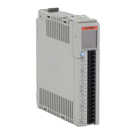
P2-04DA Analog Output
208
Wiring Diagrams
210
Configuration Settings
212
OLED Panel Display
213
P2-04DAL-1 Analog Output
214
Wiring Diagrams
216
Configuration Settings
217
P2-04DAL-2 Analog Output
218
Wiring Diagrams
220
Configuration Settings
221
P2-08DA-1 Current Analog Output
222
Wiring Diagrams
224
Module Configuration
225
P2-08DA-2 Voltage Analog Output
227
Wiring Diagrams
229
Module Configuration
230
P2-08DAL-1 Current Analog Output
232
Wiring Diagrams
234
Module Configuration
235
P2-08DAL-2 Voltage Analog Output
236
Wiring Diagrams
238
Module Configuration
239
P2-16DA-1 Current Analog Output
240
Wiring Diagrams
242
Module Configuration
243
OLED Panel Display
244
P2-16DA-2 Voltage Analog Output
245
Wiring Diagrams
247
Module Configuration
248
LCD Panel Display
249
P2-16DAL-1 Current Analog Output
250
Wiring Diagrams
252
Module Configuration
253
P2-16DAL-2 Voltage Analog Output
254
Wiring Diagrams
256
Module Configuration
257
P2-8AD4DA-1 Current Analog Input/Output
258
Wiring Diagrams
261
Module Configuration
262
OLED Panel Display
263
P2-8AD4DA-2 Voltage Analog Input/Output
264
Wiring Diagrams
267
Module Configuration
268
P2-HSI High-Speed Input Module Overview
271
HSI LED Indicators
272
HSI Input Specifications
273
HSI Status Output Specifications
275
Frequency Response
275
HSI Wiring Examples
277
P2-HSO High-Speed Output Module Overview
280
HSI LED Indicators
281
HSI Output Specifications
282
HSO Wiring Examples
284
High-Speed Module Tester Utility
289
P2-SCM Module Overview
290
SCM LED Indicators
291
P2-SCM Module Communications
292
RS-232 Serial Ports
292
Serial Port 1
293
Serial Port 2 and 3
293
Port 4
293
Serial Port 2 and 3
294
Port 4
295
Chapter 5: Installation and Wiring
298
Safety Guidelines
298
Plan for Safety
298
Three Levels of Protection
299
Orderly System Shutdown
299
System Power Disconnect
299
Emergency Stop Circuits
300
Introduction
301
Productivity 2000 Mechanical Design
301
Typical Productivity2000 System
301
Dimensions and Installation
302
Base Dimensions, Inches [MM]
302
Mounting Guidelines
303
Enclosures
303
Mounting Position
303
Mounting Clearances
303
Grounding
303
Temperature Considerations
303
Power Considerations
303
Panel Layout
304
Other Specifications
305
Agency Approvals
305
Using Mounting Rails
306
Installing the Power Supply
307
Installing the CPU
308
Installing the I/O Modules
309
Wiring Guidelines
310
Wiring to the Power Supply
310
Grounding
310
Fuse Protection
311
I/O Module Wiring Options
312
Ziplink Wiring System
312
Terminal Block with Pigtail Cable
312
Removable Terminal Blocks (Optional)
316
Terminal Block Removal
316
Planning the I/O Wiring Routes
317
System Wiring Strategies
318
CPU Isolation Boundaries
318
Sinking/Sourcing Concepts
319
I/O "Common Terminal" Concepts
320
DC Input Wiring Methods
321
DC Output Wiring Methods
321
Relay Outputs - Wiring Methods
323
Relay Outputs - Transient Suppression for Inductive Loads in a Control System
324
Chapter 6 - Communications
330
Communication Ports
330
Communications: Connectivity
337
P2-550 Port Connections
337
ASCII and Custom Protocol Functionality
342
ASCII Instructions
342
Custom Protocol Instructions
343
Communications: Ethernet
345
TCP and UDP Port Numbers
345
IP Addressing and Subnetting
345
PC Setup
346
CPU Setup
347
TCP Connection Behavior with Modbus TCP and Network Instructions
348
Communications Modbus Functionality
349
Master/Client Function Code and Data Type Support
349
Slave/Server Function Code and Data Type Support
351
Assigning Modbus Addresses to Tags
352
Modbus Options
355
Modbus Instructions
358
Network Instructions
360
Automatic Poll Versus Manual Polling and Interlocking
361
Message Queue
363
Ethernet/Ip for the Productivity Series
364
Terminology Definitions
364
Network Layer Chart
365
Ethernet/Ip Data
365
Class 1 and Class 3 Connections
366
Setup Example: Productivity2000 as Ethernet/Ip Adapter
366
Setup Example: Productivity
369
2000 As Ethernet/Ip Scanner
369
Troubleshooting Tips
372
Ethernet/Ip I/O Message Troubleshooting
374
Ethernet/Ip Explicit Message Troubleshooting
374
Pronet
375
Custom Protocol over Ethernet Functionality
376
Hardware Configuration
377
Custom Protocol Ethernet Instruction
378
Communications: Remote I/O and GS-Drives
379
Things to Consider for the Design of Remote I/O and GS-Drives
379
Configuration of Remote Slaves
380
Communications: Port Configuration
387
Ethernet Configuration
387
External Ethernet Port Settings
388
Local Ethernet Port Settings
389
Remote Access Configuration
390
Serial Configuration
391
RS-232 and RS-485 Port Settings
391
Communications: Error Codes
395
Productivity2000 Communication Error Codes
395
2000 Ethernet/Ip Error Codes
396
2000 Ethernet/Ip Error Codes
397
Chapter 7: Maintenance and Troubleshooting
404
Hardware Maintenance
404
Standard Maintenance
404
Air Quality Maintenance
404
CPU Battery Replacement
404
Diagnostics
405
Critical Errors
405
Non-Critical Errors
405
Finding Diagnostic Information
405
CPU Indicators
406
PWR Indicator
407
Incorrect Base Power
407
Faulty CPU
407
Device or Module Causes the Power Supply to Shutdown
408
Run Indicator
409
CPU Indicator
409
Communications Problems
409
I/O Module Troubleshooting
410
Things to Check
410
Some Quick Steps
410
Testing Output Points
411
Noise Troubleshooting
412
Electrical Noise Problems
412
Reducing Electrical Noise
412
Run Time Vs Stop Mode Transfer Instruction
413
Run Time Transfers
414
Stop Mode Transfers
414
Forcing I/O Points
416
Advantages of Forces
416
Enabling Forces
416
Forcing Tags in Your System
417
Identifying Forced Values
419
Force Value Timing Chart
420
Appendix A: European Union Directives (CE)
422
European Union (EU) Directives
422
Member Countries
422
Applicable Directives
422
Compliance
422
General Safety
423
Special Installation Manual
424
Basic EMC Installation Guidelines
424
Enclosures
424
Mains Filters
425
Suppression and Fusing
425
Internal Enclosure Grounding
425
Equipotential Grounding
425
Communications and Shielded Cables
426
Analog and RS232 Cables
427
Multidrop Cables
427
Shielded Cables Within Enclosures
427
Analog Modules and RF Interference
427
Network Isolation
428
Items Specific to the Productivity
429
Appendix B: Productivity2000 Error Codes
432
Communications Error Codes
432
Module Error Codes
433
CPU Error Codes
435
Project Error Codes
436
Project Error Messages
438
Advertisement
Advertisement
Related Products
Automationdirect.com DL305
Automationdirect.com P2-01AC
Automationdirect.com P2-01DCAC
Automationdirect.com P2-04AD
Automationdirect.com P2-04DA
Automationdirect.com P2-06RTD
Automationdirect.com P2-08DA-2
Automationdirect.com P2-08NTC
Automationdirect.com Categories
I/O Systems
Control Unit
Controller
Temperature Controller
DC Drives
More Automationdirect.com Manuals
Login
Sign In
OR
Sign in with Facebook
Sign in with Google
Upload manual
Upload from disk
Upload from URL