Table of Contents
Advertisement
Quick Links
Advertisement
Table of Contents

Related Manuals for Eliminator Lighting MEGA HEX L PAR


Summary of Contents for Eliminator Lighting MEGA HEX L PAR
- Page 1 MEGA HEX L PAR User Manual...
- Page 2 All non-Eliminator brands and product names are trademarks or registered trademarks of their respective companies. Eliminator Lighting and all affiliated companies hereby disclaim any and all liabilities for property, equipment, building, and electrical damages, injuries to any persons, and direct or indirect economic...
-
Page 3: Table Of Contents
C O N T E N T S General Information Limited Warranty (USA Only) Warranty Registration | Features Safety Guidelines Overview Installation Guidelines Accessory Installation IR Remote Remote Device Management (RDM) System Menu Operation Modes Primary-Secondary Set Up DMX Setup DMX Traits Color Macros Chart White Color Temperature Chart... -
Page 4: General Information
G E N E R A L I N F O R M AT I O N INTRODUCTION Please read and understand all instructions in this manual carefully and thoroughly before attempting to operate these products. These instructions contain important safety and use information. This product is intended for use by professionally trained personnel only, and is not suitable for private use. -
Page 5: Limited Warranty (Usa Only)
ADJ Products, LLC Service Department at 800-322-6337. Send the product only to the Eliminator Lighting factory. All shipping charges must be pre-paid. If the requested repairs or service (including parts replacement) are within the terms of this warranty, Eliminator Lighting will pay return shipping charges only to a designated point within the United States. -
Page 6: Warranty Registration | Features
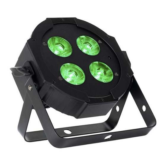
F E AT U R E S The Eliminator Mega Hex L Par is a compact, LED Par with 4 x 20-Watt, 6-IN-1 (RGBLA + UV) LEDs and Eliminator’s patented “sit-flat” design so that it may sit directly on the ground or inside truss. It includes the UC IR24 wireless IR remote control. -
Page 7: Safety Guidelines
To guarantee a smooth operation, it is important to follow all instructions and guidelines in this manual. Eliminator Lighting is not responsible for injury and/or damages resulting from the misuse of this fixture due to the disregard of the information printed in this manual. Only qualified and/or certified personnel should perform installation of this fixture and only the original rigging parts included with this fixture should be used for installation. - Page 8 S A F E T Y G U I D E L I N E S RISK GROUP 3 - RISK OF EXPOSURE TO ULTRAVIOLET UV RADIATION! FIXTURE EMITS HIGH INTENSITY WAVELENGTH OF ULTRAVIOLET UV LIGHT FROM THE UV COLOR FILTER. WEAR PROPER EYE AND SKIN PROTECTION.
- Page 9 THIS FIXTURE IS COMPOSED OF SOPHISTICATED ELECTRONIC COMPONENTS. TO GUARANTEE SMOOTH OPERATION, IT IS IMPORTANT TO FOLLOW ALL INSTRUCTIONS AND GUIDELINES IN THIS MANUAL. ELIMINATOR LIGHTING IS NOT RESPONSIBLE FOR INJURY AND/OR DAMAGES RESULTING FROM THE MISUSE OF THIS FIXTURE DUE TO THE DISREGARD OF THE INFORMATION PRINTED IN THIS MANUAL.
-
Page 10: Overview
OVERVIEW Power Mounting Yoke Display Screen Yoke Yoke Adjustment Adjustment Knob Knob Down Mode Button Button Setup Button Button Power Fuse... -
Page 11: Installation Guidelines
I N S TA L L AT I O N G U I D E L I N E S FLAMMABLE MATERIAL WARNING Keep fixture at least 7.9in. (0.2m) away from any flammable materials, decorations, pyrotechnics, etc. ELECTRICAL CONNECTIONS A qualified electrician should be used for all electrical connections and/or installations. - Page 12 I N S TA L L AT I O N G U I D E L I N E S NOTICE: The suitable environmental temperature for this lighting fixture is -4˚F to 113˚F (-20˚C to 45˚C). Do not place this lighting fixture in an environment where the temperatures fall outside of this range.
- Page 13 I N S TA L L AT I O N G U I D E L I N E S The fixture is fully operational in three different mounting positions: hanging upside-down, mounted sideways on trussing, or set on a flat level surface. Be sure this fixture is kept at least 0.2m (8in.) away from any flammable materials (decoration etc.).
- Page 14 LEDs. This issue is not specific only to Eliminator lighting fixtures, it is a common issue with lighting fixtures from all manufacturers. Although there is no true way to fully prevent this issue from happening, the guidelines below can prevent any potential damage from occurring if followed.
-
Page 15: Accessory Installation
A C C E S S O R Y I N S TA L L AT I O N FROST FILTER To install the optional frost filter, pinch the filter in the middle, being careful not to create creases. Guide the edges of the filter into the slots on either side of the fixture’s lens, then slowly release the filter and allow it to unfold until it sits flat against the fixture lens. -
Page 16: Ir Remote
I R R E M O T E The unit can only be controlled when it has been set to Primary mode. The unit will NOT re- spond to commands when it has been set to Secondary mode. When using the remote to control multiple units that are operating in primary/secondary mode, follow these steps to set up the units: 1. - Page 17 I R R E M O T E REMOTE BUTTON COLOR ASSIGNMENT The number keys (0-15) on the UC IR24 remote can each be programmed with a specialized color mix. The default factory color programs that are assigned to these keys are shown in the table below. DEFAULT REMOTE BUTTON COLOR VALUES BUTTON GREEN...
-
Page 18: Remote Device Management (Rdm)
R E M O T E D E V I C E M A N A G E M E N T ( R D M ) NOTE: In order for RDM to work properly, RDM enabled equipment must be used throughout the entire system, including DMX data splitters and wireless systems. -
Page 19: System Menu
S Y S T E M M E N U The fixture includes an easy to navigate system menu. The control panel located on the front of the fixture, provides access to the main system menu and is where all necessary system adjustments are made to the fixture. - Page 20 S Y S T E M M E N U Set DMX starting 001 - 496 Address address Channel Select DMX 12ch Mode channel mode 14ch 15ch 17ch Unit holds channels at the last values Hold Last received when DMX signal is lost SETTINGS Unit takes all...
- Page 21 S Y S T E M M E N U Activate/deactivate On / Off Screen will shut Off, 1sec - 10sec Saver Delay off after selected period of inactivity Screen locks after selected period of Display Off, 30sec, 2min - 10min Screen Lock inactivity;...
- Page 22 S Y S T E M M E N U 000 - 255 Green 000 - 255 Blue 000 - 255 Lime 000 - 255 Amber 000 - 255 000 - 255 Color Macros 000 - 063 MANUAL Manually set each Color Temp No Function, 2300K - 9900K CONTROL...
-
Page 23: Operation Modes
O P E R A T I O N M O D E S This device features 5 different operation modes which can be selected from the main system menu. These are easily configured and operated from the included UC IR24 remote, or in some cases the display screen and its control buttons. - Page 24 O P E R A T I O N M O D E S RGBLA + UV DIMMER MODE: The unit displays a single, custom mixed static color. Display Screen Control: 1. From the main system menu, press UP and DOWN to navigate to “Manual Control”, then press SETUP.
- Page 25 O P E R A T I O N M O D E S DMX CONTROL MODE: Control the unit using a DMX controller. Only available from Display Screen Control. 1. Use a DMX cable to connect the output port of your DMX controller to the DMX Input port of your first fixture.
-
Page 26: Primary-Secondary Set Up
P R I M A R Y - S E C O N D A R Y S E T U P This function allows you to link units together to run in a Primary-Secondary set-up, in which one unit will act as the controlling unit and the others will react to the controlling unit’s built-in programs. -
Page 27: Dmx Setup
D M X S E T U P DMX-512: DMX is short for Digital Multiplex. This is a universal protocol used as a form of communication between intelligent fixtures and controllers. A DMX controller sends DMX data instructions from the controller to the fixture. - Page 28 D M X S E T U P Special Note: Line Termination. When longer runs of cable are used, you may need to use a terminator on the last unit to avoid erratic behavior. A terminator is a 110-120 ohm 1/4 watt resistor which is con- nected between pins 2 and 3 of a male XLR connector (DATA + and DATA -).
- Page 29 D M X S E T U P DMX Addressing: All fixtures should be given a DMX starting address when using a DMX controller, in order to ensure that the correct fixture responds to the correct control signal. This digital starting address is the channel number from which the fixture starts to “listen”...
-
Page 30: Dmx Traits
D M X T R A I T S CHANNEL FUNCTION VALUES 12Ch 14Ch 15Ch 17Ch 000 - 255 All Red, 0% to 100% 000 - 255 All Green, 0% to 100% 000 - 255 All Blue, 0% to 100% 000 - 255 All Lime, 0% to 100% 000 - 255 All Amber, 0% to 100% 000 - 255 All UV, 0% to 100%... - Page 31 D M X T R A I T S CHANNEL FUNCTION VALUE 12Ch 14Ch 15Ch 17Ch 000 - 255 Auto Programs Fade, least to most Dim Mode 000 - 020 Default to unit setting 021 - 040 Standard 041 - 060 Stage 061 - 080 TV 081 - 100 Architectural 101 - 120 Theatre...
-
Page 32: Color Macros Chart
C O L O R M A C R O S C H A R T DMX VALUES COLORS DMX VALUES COLORS 000 - 003 128 - 131 G+B+L 004 - 007 132 - 135 G+B+A 008 - 011 Green 136 - 139 G+B+UV 012 - 015... -
Page 33: White Color Temperature Chart
W H I T E C O L O R T E M P E R AT U R E C H A R T DMX VALUES COLOR TEMP (K) DMX VALUES COLOR TEMP (K) 2300 6200 2400 6300 2500 6400 2600 6500... -
Page 34: Dimmer Curve
D I M M E R C U R V E DIMMER 100% Time (ms) 0 Sec Rise Time Down Time 0 sec Fade Time 1 sec Fade Time Dimming Curve Ramp Effect Rise Time (ms) Down Time (ms) Rise Time (ms) Down Time (ms) Standard (default) Stage... -
Page 35: Power Linking | Cleaning
P O W E R L I N K I N G This feature allows multiple units to be linked together by way of the power input and output sockets. The maximum number of devices that can be connected in this manner is as follows: •... -
Page 36: Specifications
S P E C I F I C AT I O N S • Vibrant slim flat black Par with 4 x 20-Watt, 6-IN-1 Hex (RGBLA+UV) LEDs • HEX LEDs allow for a wider pallet of colors like hot pink, lime green and electric blue •... -
Page 37: Dimensional Drawings
D I M E N S I O N A L D R AW I N G S 6.6in (168mm) 3.4in (89mm) 9.1in (230mm) 1.7in (42mm) 6.9in (175mm) 7.7in (196mm) -
Page 38: Fcc Statement
F C C S TAT E M E N T This device complies with Part 15 of the FCC rules. Operation is subject to the following two condi- tions: (1) this device may not cause harmful interference, and (2) this device must accept any interfer- ence received, including interference that may cause undesired operation. - Page 39 This page intentionally left blank.
Need help?
Do you have a question about the MEGA HEX L PAR and is the answer not in the manual?
Questions and answers