Table of Contents
Advertisement
Quick Links
Installation, Operating and
Maintenance Instructions
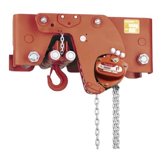
HADEF Spur Gear Hoist
Type 29/12-EX
Ultra-low headroom configuration
^
with monorail hand geared trolley
Explosion proof design
II 2G Ex h IIB T4 Gb or
II 2G Ex h IIB T3 Gb or
DANGER!
Not to be used with IIC gases and IIB gases hydrogen sulphide and ethylene oxide and
light metal and shock sensitive dusts!
It is not allowed to use the equipment in area at risk from explosion where gas AND
dust does both exist at the same time!
5.52.182.01.01.05
HH
II 2D Ex h IIIA T135° C Db
II 2D Ex h IIIA T200° C Db
Rev.05
Advertisement
Table of Contents

Related Manuals for HADEF 29/12-EX


Summary of Contents for HADEF 29/12-EX
- Page 1 Installation, Operating and Maintenance Instructions HADEF Spur Gear Hoist Type 29/12-EX Ultra-low headroom configuration with monorail hand geared trolley Explosion proof design II 2G Ex h IIB T4 Gb or II 2D Ex h IIIA T135° C Db II 2G Ex h IIB T3 Gb or II 2D Ex h IIIA T200°...
-
Page 2: Table Of Contents
Heinrich de Fries GmbH Heinrich de Fries GmbH, Gauss Str. 20, D-40235 Düsseldorf Heinrich De Fries GmbH will be named HADEF in the following text. Original operating- and maintenance instructions in German language. Translation in other languages is made of the German original. -
Page 3: Information
Maintenance ..................19 11.1 General ........................... 19 11.2 Monitoring ........................19 11.3 Replacing the load chain ....................19 Inspection ..................20 12.1 Periodic checks ......................20 12.2 Checking the load chain ....................20 12.3 Checking the load hook ....................21 12.4 Checking - pawl ...................... -
Page 4: Safety
Failure to follow the instructions of this manual can lead to unpredictable hazards. For any resulting damage or personal injury, HADEF assumes no liability. The unit was designed and built following a risk analysis and careful selection of the harmonized standards that are to be complied with, as well as other technical specifications. -
Page 5: Requirements For The Operating Personnel
Any safety and warning signs on the devices are not removed and remain legible. Devices for use in area prone to explosion must (from customer's side) be earthed with a shunting resistor of < 10 Ω against earth. WARNING! It is not allowed to make constructive changes of the equipment! Requirements for the operating personnel The units may only be operated by qualified persons that are appropriately trained and that are familiar with it. -
Page 6: Basic Safety Measures
NOTICE! If the units are not used appropriately, it is not possible to ensure safe operation. The owner and operator have sole liability for all personal injury and damage to property arising from inappropriate use. DANGER! It’s only allowed to use the unit in the EX-classification which is named on the type plate; or in lower classes Basic safety measures Observe installation-, operation and maintenance instruction. - Page 7 Check the grease level of the bearings regularly Exchange friction surfaces in time and (an exception to this are electric units - maintenance of the brakes must only be effected by HADEF). Protect the device from impact, friction, rough handling and moisture.
-
Page 8: Explosion Protection
Explosion protection The EX classification of the unit is indicated on a separate plate, situated on the unit. Illustration 2 Example of ATEX classification: Ex h CE-marking European Union explosion-proof operating material danger of mine damp device group / application other areas prone to explosion for use in zone 0 device category... - Page 9 DANGER! The classification for the device can be found on the EX-type plate on the unit. The device must only be used in the classification stated or in a lower classification. 2.6.2 Surface temperature of the devices DANGER! The temperature class mentioned on the EX-type plate on the unit must be observed, - make sure that the max.
- Page 10 2.6.4 Explosion hazards … recognizing and preventing! 5.52.182.01.01.05...
-
Page 11: Transport And Storage
EX-classification mentioned on the EX-type plate or lower EX classification. Design HADEF Spur gear hoists, ultra low headroom, HH are monorail trolley with installed lifting units. The use of lifting and driving unit effected manually by hand chain. 5.52.182.01.01.05... -
Page 12: Functions
„no appropriate use“ of the hoist ! This may lead to unforeseeable danger, with injury of persons or damage of equipment! HADEF is not liable for any damage or injury that results hereof! 1 chain end fastening... -
Page 13: Technical Data
Load hook Forged steel. Rotating, this facilitates attaching the load and avoids twisting of the chain. With safety catch. Overload protection Hoists with overload protection protects the hoist by a slipping clutch from damage by overload. When the slipping clutch operates, lifting of the load is stopped. Lifting is only possible again after the load has been lowered and reduced to nominal load. -
Page 14: Trolley
Trolley For assembly on a beam a travel limit must be placed at either end of the track. This must be attached so that any elastic limitation buffer or the trolley wheels are driven against them in their end position when moving. Generally, additional lifting gear (e.g. -
Page 15: Installation On The Beam
Installation on the beam Hoists according to table 1 Illustration 7 Assemble the side plates (1) of the trolley with load bars (2), distance tubes (5), washers (6), hexagon nuts (3) and lock nuts (4) to width "X". Tighten the hexagon nut (3) and lock nut (4) thoroughly. -
Page 16: Tools
6.4.1 Bolt securing with collar Securing the load bolts with set collars (1) and safety screws (3). In order to adjust the beam flange width dismantle the safety screws (3) at one trolley side. After adjustment of dimension "X" and installation on the beam, install the safety screws (3) again and secure them with a nut (4). -
Page 17: Control
Capacity Size Tool SW17 Roller chain 1000-50000 tension device diff. Control Only people that are familiar with the operation of the lifting devices and cranes may be entrusted with their operation. They must be authorized by the employer for the operation of the equipment. The employer must ensure that the operating instructions are available near the equipment and that they are accessible for the operating personnel. -
Page 18: Commissioning
GEFAHR! Working situations with no guarantee that the minimum load is charged, are forbidden! Commissioning General Should the unit be used in Germany: Please observe the validated, national accident prevention regulations. For other countries: Inspections as above. Please observe the national rules and regulations and the instructions in this manual! NOTICE! Hoists up to 1000 kg capacity and without motor-driven trolleys of hoisting unit must be tested by a “qualified person”... -
Page 19: Functional Test
Functional test 10.1 Checks before the initial start-up Lifting gear Load chains must not be twisted. Lubricate the load chain with gear oil or suitable chain lubricant before first loading. Trolley drive The open-lying teeth of the trolley drive must be lubricated. Hand gear for hand geared trolley Ensure correct fit of the hand chain, it must not be twisted and must hang freely. -
Page 20: Inspection
Inspection 12.1 Periodic checks Independently from the regulations of the individual countries, lifting devices must be checked at least yearly by a qualified person or licensed qualified person regarding its functional safety. 12.1.1 Components to be checked The following must be checked: Dimensions of load chain, load hooks, pawls, bolts, ratchet wheels, brake linings. -
Page 21: Checking The Load Hook
Chain dimensions Table 1 Dimensions Chain size 4x12 4,2x12,2 5x15 5,6x15,8 5,6x17 6x18 6,3x19,1 7,1x20,1 105,6 136,6 138,2 170,6 179,1 194,2 203,9 216,4 227,9 12,7 12,8 15,7 16,6 18,9 21,2 21,2 Table 2 Dimensions Chain size 7,1x21 7,9x23 8x24 9x24,8 9x27 10x28,1 10x30... -
Page 22: Checking - Brake System
12.5 Checking - Brake System Ratchet wheel with brake linings 1000 12,2 2000 16,2 3200 - 6300 16,5 15,7 Ratchet wheel (A) and brake linings (B) 2x B 10000 - 30000 Service 13.1 Load chain Wear at the links is mainly due to insufficient maintenance of the chain. To ensure optimal lubrication of the links, the chain must be lubricated at regular intervals, depending on usage. -
Page 23: Pulleys
13.2 Pulleys Recommendation Interval FUCHS Pulleys Acc. to demand 12 month RENOLIN PG220 13.3 Load hook Check bearings and pulleys yearly Clean and lubricate the bearings of hooks and pulleys with grease Slight bearings are maintenance free When bearings resp. slight bearings are worn of, change the complete pulley Recommendation Interval Load hook... -
Page 24: Lubricant - Selection
13.8 Lubricant - Selection FUCHS SHELL ESSO MOBIL TOTAL CASTROL KLÜBER Renolit FEP 2 Alvania EP 2 Unirex EP 2 Mobilux EP 2 MULTIS EP2 Stabylan 5006 Optimol Viscoleb 1500 Klüberoil 4UH 1-1500 Wolfracoat 99113 Chain lubricant OKS 451 13.9 Lubricant for food industry - Selection (as option*) KLÜBER SHELL... -
Page 25: Decommissioning
Decommissioning WARNING! It is essential that the following points are observed in order to prevent damage to the equipment or critical injury when the device is being decommissioned: It is mandatory that all steps for decommissioning the machine are carried out in the indicated sequence: First secure the working area for decommissioning, leaving plenty of space.
Need help?
Do you have a question about the 29/12-EX and is the answer not in the manual?
Questions and answers