Table of Contents
Advertisement
Quick Links
Installation, Operating and
Maintenance Instructions
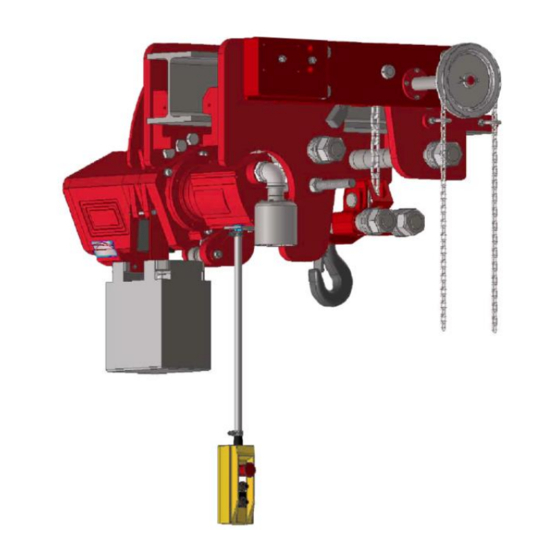
HADEF Pneumatic Chain Hoist
Type 29/06AP-EX
Ultra-low headroom configuration
^
with monorail hand geared trolley
with monorail pneumatic trolley
with monorail trolley Big Bag
Explosion proof design
II 2G IIB c T4 or
II 2G IIB c T3 or
DANGER!
Not to be used with IIC gases and IIB gases hydrogen sulphide and ethylene oxide and
light metal and shock sensitive dusts.
It is not allowed to use the equipment in area at risk from explosion where gas AND
dust does both exist at the same time!
o
5.52.181.01.01.07
II 2D c 135°C
II 2D c 200°C
Rev.07
APH
APP
APHL and APPL
Advertisement
Table of Contents

Related Manuals for HADEF 29/06AP-EX


Summary of Contents for HADEF 29/06AP-EX
- Page 1 Installation, Operating and Maintenance Instructions HADEF Pneumatic Chain Hoist Type 29/06AP-EX Ultra-low headroom configuration with monorail hand geared trolley with monorail pneumatic trolley with monorail trolley Big Bag APHL and APPL Explosion proof design II 2G IIB c T4 or II 2D c 135°C...
-
Page 2: Table Of Contents
Heinrich de Fries GmbH Heinrich de Fries GmbH, Gauss Str. 20, D-40235 Düsseldorf Heinrich De Fries GmbH will be named HADEF in the following text. Original operating- and maintenance instructions in German language. Translation in other languages is made of the German original. -
Page 3: Information
11.1 Checks before the initial start-up ................. 21 11.2 Functional test ....................... 21 Maintenance ..................22 12.1 General ........................... 22 12.2 Monitoring ........................22 12.3 Replacing the load chain ....................22 12.4 Pneumatic motor ......................23 12.5 Overload protection ....................... 23 12.6 Stretch the roller chain. -
Page 4: Indications To Determine The Used Part Of The Theoretical Usage Life
“winches, lifting and pulling devices”. NOTICE! Commitment A general overhaul may only be performed by HADEF or by a specialized company, authorized by HADEF. Safety DANGER! To assess the intended use of the devices correctly, the user must carry out an Ex-zone classification. -
Page 5: Requirements For The Operating Personnel
regulations. For explosion-proof equipment, all these parts must be approved for use in area prone to explosion, or they must be suitable for use in area prone to explosion. The owner is responsible for this. However, in everyday operation this degree of safety can only be achieved if all measures required are taken. -
Page 6: Basic Safety Measures
DANGER! It’s only allowed to use the unit in the EX-classification which is named on the type plate; or in lower classes EX II 2G IIB c T4 or EX II 2D c 135°C EX II 2G IIB c T3 or EX II 2D c 200°C DANGER! It is not allowed: ... - Page 7 Check the grease level of the bearings regularly Exchange friction surfaces in time and (an exception to this are electric units - maintenance of the brakes must only be effected by HADEF). Protect the device from impact, friction, rough handling and moisture.
-
Page 8: Explosion Protection
3G/D 0,20,1,21 2G/D 0,20 0,20,1,21,22 0,20,1,21,2 0,20,21,22 0,20,1,2 Explosion protection The EX classification of the unit is indicated on a separate plate, situated on the unit. Illustration 2 Example of ATEX classification: CE-marking European Union explosion-proof operating material danger of mine damp device group / application other areas prone to explosion Use in zone 0... - Page 9 The classification for the device can be found on the EX-type plate on the unit. The device must only be used in the classification stated or in a lower classification. 2.6.2 Surface temperature of the devices DANGER! The temperature class mentioned on the EX-type plate on the unit must be observed, - make sure that the max.
- Page 10 Explosion hazards … recognizing and preventing! 2.6.4 5.52.181.01.01.07...
-
Page 11: Transport And Storage
The EX-classification is mentioned on the EX-type plate on the hoist. The use of the unit is only allowed for the EX-classification mentioned on the EX-type plate or lower EX classification. Design HADEF pneumatic chain hoists, with ultralow design and pneumatic trolley, Type 29/06 APP and hand-geared trolley Type 29/06 APH are monorail trolleys combined with hoists. -
Page 12: Functions
All hoists are fitted with high-quality lifting gears of the reliable AK series. 4.4.1 Motor Type of chain hoist 70/06AP, 70/06AP-EX 28/06AP, 28/06 AP-EX Pneumatic motor 29/06AP, 29/06AP-EX 29/06APL Big Bag, 29/06APL Big Bag-EX 4.4.2 Gear Lifting gear with ventilation screw AK 4-8 Precision Spur Gear AK9+10 Precision Planetary Gear... -
Page 13: Technical Data
4.4.5 Overload protection mechanical stop by spring Pressure reducing valve assembly Slipping clutch Type Standard Option Standard Option 70/06AP+EX AK 4-8 AK 9+10 AK 4-10 28/06AP+EX AK 4-8 AK 4-10 AK 9+10 29/06AP+EX AK 4-8 AK 4-10 AK 9+10 4.4.6 Load chain acc. -
Page 14: Installation
Table 2 Capacity 8000 10000 12000 16000 20000 25000 30000 40000 50000 60000 hoisting unit AK 9 AK 9 AK 9 AK 9 AK 9 AK 9 AK 9 AK 9 AK 9 AK 9 Number of chain falls 2 x 4 2 x 5 2 x 6 FEM 9.511/ EN 818-7... -
Page 15: Devices With A Load Capacity Of Up To 6,3 T
Devices with a load capacity of up to 6,3 t 6.2.1 Setting and checking the gauge The trolley and the bottom block can be adjusted "B" beam flange width to different beam flange widths. "X" gauge Setting to the relevant beam flange width “B” is to be made as follows: ... -
Page 16: Devices From 8 T Up To 60 T Capacity
Devices from 8 t up to 60 t capacity 6.3.1 Installation on the beam Secure the load bars with set collars (1) and safety screws (3). In order to adjust the beam flange width and for installation on the beam, dismantle the safety screws (3) at one trolley side. -
Page 17: Tools
Tools Capacity Size Tool SW36 1,5t + 2t SW46 2,5t + 3,2t SW55 load bolt 5t + 6,3t SW60 7,5t + 10t SW75 12,5 t SW22 load bolt with 16t - 60t SW24 locking ring SW46 SW55 Load bolts bottom 2,5t - 3,2t SW60 block... - Page 18 Direct control 1 Emergency-Stop 2 Lifting 3 Lowering Illustration 7 Indirect pneumatic control 1 Emergency stop 2 lifting 3 lowering Hoists combined with trolleys have control switches where push buttons for trolley movement are added. Special design units can be supplied upon request.
-
Page 19: Operation
Operation The following, important points must be observed when operating the equipment: Read the safety instructions. Never load the devices beyond their working load limit. The prescribed maintenance intervals must be adhered to. The lifting tackle or the load must be securely attached to the hook and be seated at the bottom of the hook. -
Page 20: Gear
The oiler enriches the air with oil. Setting of oil addition: approx. 2 drops of oil must be added per minute. NOTICE! HADEF does not assume any responsibility for damage caused by non-observance of the instructions. CAUTION! Should the unit be assembled at the customer, the maintenance unit is supplied without oil. -
Page 21: Power Operated Hoists With Chain Container
Power operated hoists with chain container: Due to the transport and / or installation of the hoist on the beam, the position of the load chain in the chain container can change unfavorably. WARNING! It is mandatory before the first commissioning: ... -
Page 22: Maintenance
Then check the brake function under load. After releasing the buttons of the control switch, the load must be securely held. Trolleys Carefully move the trolley to the end positions and check the positions of the end stops. NOTICE! The limit switch function will only work if the movement direction of the load (lifting - lowering) corresponds to the push buttons of the control switch. -
Page 23: Pneumatic Motor
for hoists Type AK 9-10 with planetary gear NOTICE! The weld seam of the chain must lie to the outer side and must not be in contact with the sprocket wheels. 12.4 Pneumatic motor The thickness of the brake lining must be checked at least once a year. ... -
Page 24: Stretch The Roller Chain
12.6 Stretch the roller chain. Only applicable for hoists acc. to table 2 Tension of the roller chain must be checked and adjusted if necessary. For correct adjustment there is a mark on the tension device (B). Illustration 18 Procedure: ... -
Page 25: Checking The Load Chain
13.2.2 Inspection intervals Inspection Inspection Inspection 1st maintenance daily after maintenance maintenance maintenance commissioning checks 3 months every every every 3 months 12 months 36/60 months Inspection of the equipment by a qualified person (periodic inspection) screw connections brake function - brake discs overload protection as slipping clutch (if relevant) overload protection by current cut-off (electric hoist) (if relevant) -
Page 26: Checking The Load Hook
13.4 Checking the load hook Load hook X = measuring distance hook mouth width Y = measured length from hook no. 6 H = thickness of hook saddle Illustration 22 Hoists according to table 1 Please fill in the measured values before Capacity in kg/ chain falls Dimension... -
Page 27: Service
Service 14.1 Load chain Wear at the links is mainly due to insufficient maintenance of the chain. To ensure optimal lubrication of the links, the chain must be lubricated at regular intervals, depending on usage. Lubricate the chain with oil that creeps. ... -
Page 28: Hoist Gear
14.4 Hoist gear Low maintenance. Regular lubricant checks required Exchange synthetic lubricants after 3 years Shorter maintenance intervals for particularly difficult operating conditions, e.g. increased dust and pollution loads or constant operation of the hoist with the highest load ... -
Page 29: Pneumatic Motor
14.7 Pneumatic motor The pneumatic motor must be lubricated continuously by a maintenance unit. If not otherwise agreed, the maintenance unit must be installed by the customer. Should a maintenance unit be part of the consignment, the oiler must be filled with oil before the first start. After longer periods of standstill, gummy oil or slight rust may lead to the fact that the motors do not start at once or do not perform well. -
Page 30: Remedy
Secure the working area of moving parts of the unit. Please read the chapter "Safety instructions". Notes on the repair of faults are found in the following table. For the repair of failures please contact our service department. CAUTION! Trouble caused by wear or damage to parts such as wire ropes, chains, chain wheels, axes, bearings, brake parts, etc., must be remedied by replacing the parts with original spare parts. -
Page 31: Temporary Decommissioning
It is mandatory that all steps for decommissioning the machine are carried out in the indicated sequence: First secure the working area for decommissioning, leaving plenty of space. Read the chapter "Safety instructions". Disassembly is carried out in reverse order to the assembly. ...
Need help?
Do you have a question about the 29/06AP-EX and is the answer not in the manual?
Questions and answers