Table of Contents
Advertisement
Quick Links
Installation, Operating and
Maintenance Instructions
HADEF Electric Chain Hoist
Type 29/06ES - Synchro
Ultra-low headroom configuration
^
with monorail hand geared trolley
with monorail electric trolley
NOTICE!
The installation or mounting instructions for incomplete machines you'll find in chapter "Installation"
o
by Heinrich de Fries GmbH
Heinrich de Fries GmbH, Gauss Str. 20, D-40235 Düsseldorf
Heinrich De Fries GmbH will be named HADEF in the following text.
5.52.180.00.01.09
EHS - Synchro
EES - Synchro
Rev.09
Advertisement
Table of Contents

Related Manuals for HADEF 29/06ES


Summary of Contents for HADEF 29/06ES
- Page 1 The installation or mounting instructions for incomplete machines you’ll find in chapter “Installation” by Heinrich de Fries GmbH Heinrich de Fries GmbH, Gauss Str. 20, D-40235 Düsseldorf Heinrich De Fries GmbH will be named HADEF in the following text. 5.52.180.00.01.09 Rev.09...
-
Page 2: Table Of Contents
Original operating- and maintenance instructions in German language. Translation in other languages is made of the German original. A copy may be requested in writing or is available for download on www.hadef.com Subject to changes. Table of Contents Information ..................3 Indications to determine the used part of the theoretical usage life. -
Page 3: Information
Inspection ..................19 13.1 General Overhaul for motor-driven units ..............19 13.2 Periodic checks ....................... 19 13.3 Checking the load chain ....................20 13.4 Checking the load hook ....................21 Inspection – Gear – Oil level ..................21 13.5 Service ....................21 14.1 Load chain ........................ -
Page 4: Safety
“winches, lifting and pulling devices”. NOTICE! Commitment A general overhaul may only be performed by HADEF or by a specialized company, authorized by HADEF. Safety Warning notice and symbols Warnings and notice are shown as follows in these instructions: This means that there is a high risk that leads, if it is not avoided, to death or severe injury. -
Page 5: Requirements For The Operating Personnel
This personnel is regularly trained in all applicable matters regarding safety at work and environmental protection, and that they are familiar with the operating manual and, in particular, the safety instructions it contains. Any safety and warning signs on the devices are not removed and remain legible. ... -
Page 6: Basic Safety Measures
DANGER! The use is not allowed: for pulling loose of stuck loads, dragging of loads and inclined pulling. in explosive atmosphere, except the unit is especially modified for it and marked by an indication label. in reactor containment vessels. ... -
Page 7: Transport And Storage
WARNING! The following is not allowed: to lift another load than the nominal safe working load to manipulate the sliding clutch if units are equipped with The use of elongated or damaged chains or wire ropes. Replace them immediately by new, original parts. -
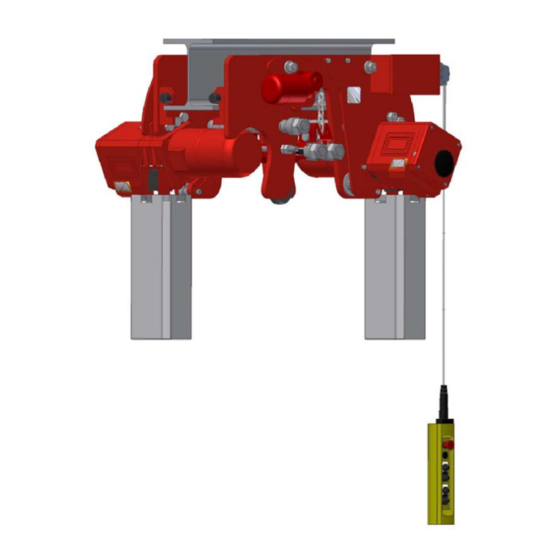
Page 8: Design
Design HADEF Electric Chain Hoists, ultralow headroom configuration Type 29/06 EHS - with hand geared trolley Type 29/06 EES - with electric trolley With two hoisting gears which ensures low oscillation during lifting and lowering. Especially suitable to be combined with jib cranes. - Page 9 Trolley gear Combination of worm gear and motor Closed design - ventilation not necessary. 4.4.3 Control Control switch with emergency stop Classification of control according to lifting gear sizes Kind of control Hoisting unit Direct control Low voltage control Radio control Frequency control AK4-7 AK8-10...
-
Page 10: Technical Data
Technical data Capacity 1000 2000 2500 3200 Hoisting unit Number of chain falls FEM 9.511/ ISO 4301 2m/M5 2m/M5 2m/M5 2m/M5 2m/M5 Load chain 5x15 5x15 7x21 9x27 9x27 Load bar 1N 74-150 74-150 82-156 106-223 106-223 for beam flange width 2N 151-220 151-220 157-210... -
Page 11: Devices With A Load Capacity Of Up To 6,3 T
Devices with a load capacity of up to 6,3 t 6.2.1 Setting and checking the gauge The trolley and the bottom block can be adjusted "B" beam flange width to different beam flange widths. "X" gauge Setting to the relevant beam flange width “B” is to be made as follows: ... -
Page 12: Chain Container Installation
Place a 2 mm thick sheet metal strip each under the 3 wheels which are not driven, loosen nuts (3,4) and (9) slightly and put the device under load at the load hook until the rollers are under pressure. ... - Page 13 Emergency stop Illustration 4 Arrow keys = drive left / right Illustration 5 Arrow keys = Lifting / Lowering Illustration 6 System start (optional) Illustration 7 Push button functions (E) Relieved push button = stand still push button half pushed = slow speed push button pushed completely = fast speed Illustration 8 Red Emergency-Stop button...
-
Page 14: Operation
Operation The following, important points must be observed when operating the equipment: Read the safety instructions. Never load the devices beyond their working load limit. When changing the motor turning direction, allow the motor to come to a standstill first. ... -
Page 15: Power Supply
The low-maintenance D.C. spring-pressure brakes are connected at the factory according to the wiring diagram. 9.2.4 Wiring diagram Wiring diagrams are situated in the terminal box or can be requested from HADEF by metioning of serial number. 9.2.5 Assignment recommendation of line cross-sections and fuses Assignment of line cross-sections and fuses must be done acc. -
Page 16: Safety Check
WARNING! It is mandatory before the first commissioning: that the complete load chain without load with the utmost care from the chain container is driven i.e. when lowering, pay special attention to the load chain on the chain container side, so that the load chain can run properly through the hoist without being twisted ... -
Page 17: Maintenance
NOTICE! The limit switch function will only work if the movement direction of the load (lifting - lowering) corresponds to the push buttons of the control switch. Maintenance 12.1 General All monitoring, servicing and maintenance operations are to ensure correct functioning of the equipment; they must be effected with utmost care. -
Page 18: Brake Motor
12.4 Brake motor Brake: 180 V DC chain hoist Brake Brake nominal braking Tightening Nominal air gap air gap Rotor strength moment moment max. min. screw T/chain falls 2,5/2 to 10/4 8/2 to 60/12 0,75 12.4.1 Assembling the brake 1 Insert the retaining ring (1) into the shaft slot. 2 Insert the feather key (2) into the motor shaft. -
Page 19: Inspection
12.5.1 Slipping clutch Illustration 13 12.5.2 Mechanical spring assembly Illustration 14 In case of overload the load must be lowered until it reaches the ground so that the spring assembly can release. Only thereafter it is possible to repeat the lifting motion. Illustration 15 12.5.3 Electronic hoisting power limiter (as option, except serial AT) -
Page 20: Checking The Load Chain
13.2.2 Inspection intervals Inspection Inspection Inspection 1st maintenance daily after maintenance maintenance maintenance commissioning checks 3 months every every every 3 months 12 months 36/60 months Inspection of the equipment by a qualified person (periodic inspection) screw connections brake function - brake discs overload protection as slipping clutch (if relevant) overload protection by current cut-off (electric hoist) (if relevant) -
Page 21: Checking The Load Hook
13.4 Checking the load hook Load hook X = measuring distance hook mouth width Y = measured length from hook no. 6 H = thickness of hook saddle Illustration 19 Please fill in the measured Dimension Capacity in kg/ chain falls values before 500/2 2500/2... -
Page 22: Pulleys
Recommendation Interval oil for example: FUCHS RENOLIN PG 220 or special chain lubricant Load chain 0,2 l 3 month Use NO grease! CAUTION! Do not use grease for lubrication of load chain. Without lubrication, manufacturer's warranty and/or liability will be void. 14.2 Pulleys Recommendation... -
Page 23: Trolley
14.5 Trolley Trolleys are lifetime lubricated, Refill lubricant is normally not necessary. Lubricate gear rim and pinion drive each ¼ year or if required more often, with grease. Recommendation Interval Pulleys FUCHS Gear rim 0,1 kg 3 month RENOLIT FEP2 Drive pinion Travelling gear... -
Page 24: Remedy
Remedy Problem* Unit Cause Remedy No main power Check connection to mains supply Unit cannot be switched on Electric Hoists exchange 2 phases Phase sequence not correct (with low voltage control) (see waring note at the plug) Fuse burnt out Replace the fuse Defective switching unit in the control button switch Replace the switching unit... -
Page 25: Temporary Decommissioning
17.1 Temporary decommissioning Measures are as above. Also read the chapter “Transport and storage”. 17.2 Final decommissioning/disposal Measures are as above. After disassembly, ensure that the disposal of the equipment and any materials it contains is carried out in accordance with environmental regulations.
Need help?
Do you have a question about the 29/06ES and is the answer not in the manual?
Questions and answers